Kozo A3 in 1.5" scale

Home Model Engine Machinist Forum

Help Support Home Model Engine Machinist Forum:

This site may earn a commission from merchant affiliate links, including eBay, Amazon, and others.
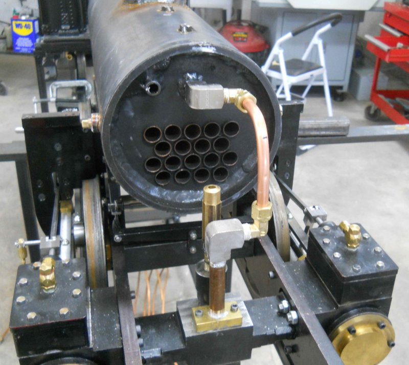
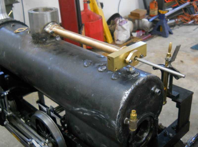
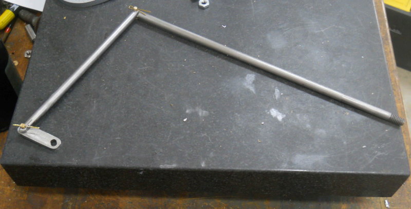
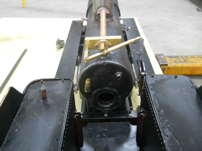
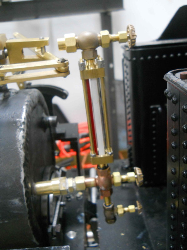
After some advice from a number of other builders, I believe I have located the "best" spot for the injectors; the water inlet will be about level with the top of the frame, and as far back as I can get it. I have some ideas about routing the water input but will have to experiment a bit before finalizing the plan.

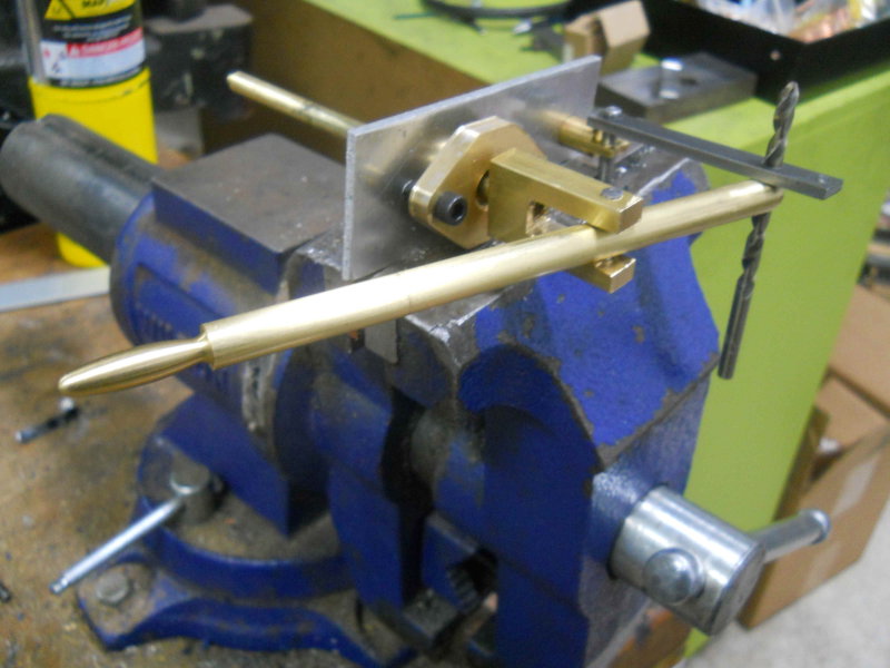
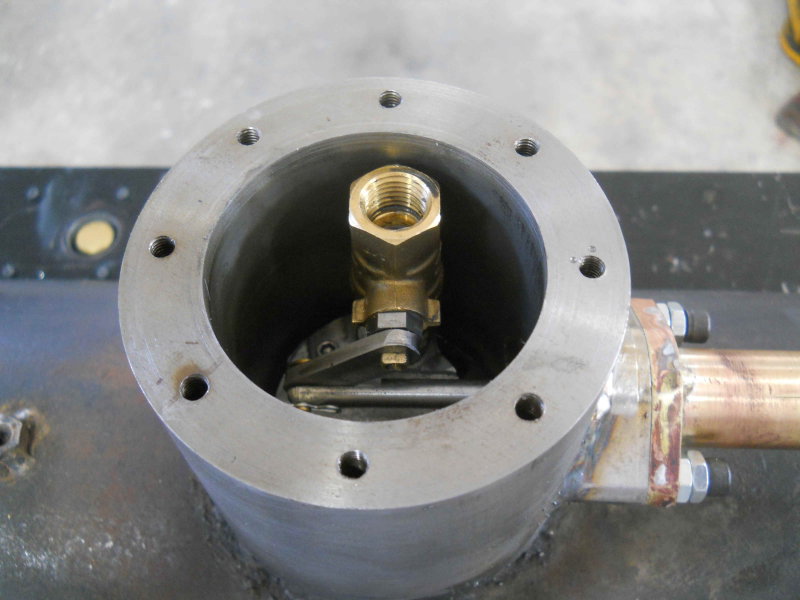
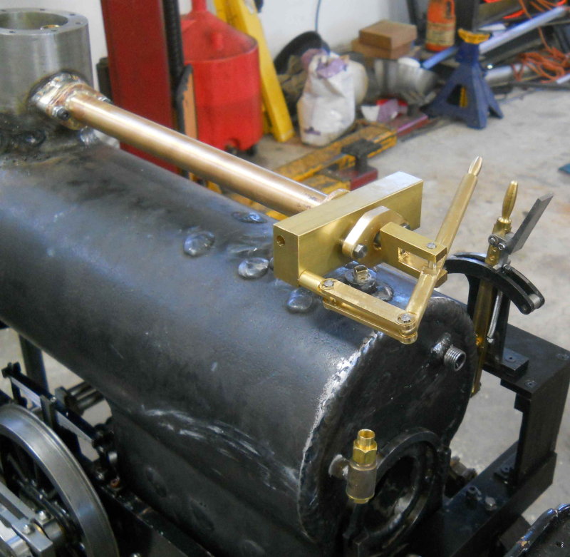
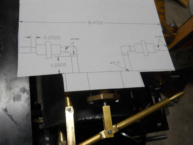
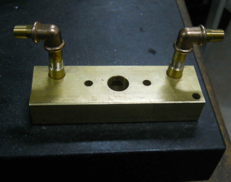
In the meantime I built a pair of parts that will connect the Locoparts blowdown valves to the boiler. On the .75" scale model, the single valve is screwed into the boiler directly with no frame in the way. On the 1.5 scale version, he specifies a single valve going through the left frame only. I will have a blowdown on both sides, and rather than build them I purchased a pair from Locoparts. The male pipe thread on these is too short to pass through the frame and screw into the boiler, so an extension is needed. Originally I was thinking that a short nipple and a bushing would be the easy way to go, but today I decided to just make each as a single brass part. Here's the result:

large.jpg


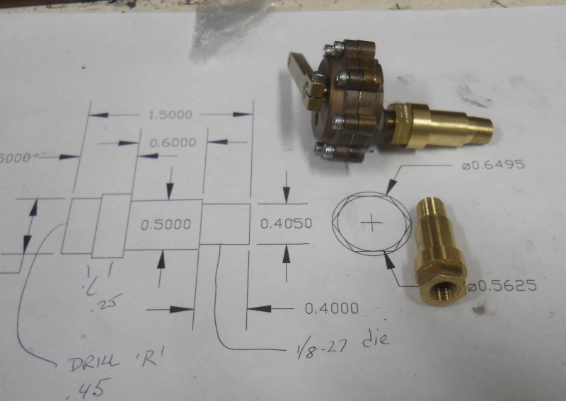
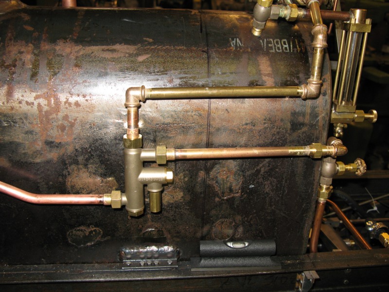
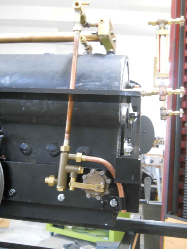
These will position the valve outboard of the frame about 3/4 of an inch so that the lever will now be under the walk board. This will allow me to attach a lifter that passes through the board and that can be activated when the locomotive is moving. It should also be possible to route the water feed line to the injectors behind the valve rather than in front.

I also countersunk the hole in the rear footboard so that the draw bar pin is recessed and no longer interferes with the fire door.
 
I drilled a second hole in the bracket to move it higher, as shown. The bottom of the injector is still only about an inch above the rails. I'll probably try a bit of an s-curve on the copper tube to position the injector a bit higher.

The Superscale Economy injector will lift fairly well - on my Shay it's fairly high and has no trouble injecting even when the tender is about dry. I had to look around to get an image of the off side but here it is in the final position:

shay_plumbing_injector_small.jpg


(One of these days I'm going to direct the overflow away from the frame...)
 
Is that valve on the water line what you use to start/stop, vs. a valve on the tender?

It's used to 'throttle' the injector so yes, I put it there instead of the tender. Works OK either place. One thing I was told that would not work was to plumb the axle pump bypass through the injector input (i.e. the return to tender line). It works fine but you can see the axle pump's impulses affecting the feed when the tender is very low - the overflow cycles a little bit.

I don't really want to hijack this thread but here's a shot from last year:

shay_07_2012.jpg
 
KVOM
Still following your interesting build of the loco. I do not think I will be building a loco in the near future (nowhere to run it locally) but it is still fascinating seeing it slowly come together.

Keep it up.

Vince
 
Built a mockup of my throttle design to check the geometry. It looked good when I drew it in Draftsight, but I needed to make sure the movement was at least fairly smooth. Seems to be good, and I get the 2" travel needed to open the valve full closed to full open with a 1" crank.

large.jpg
 
I got quite a bit done over the weekend, esp. since the Jeep is awaiting parts elsewhere and there is room in the shop. Since the club's hydro test day is coming up next month, I decided to plug as many holes as possible in the boiler. So in addition to actual plugs, I also screwed in the blowdown valves and boiler checks. I discovered that for a boiler check I needed to either do it before putting the boiler on the chassis, or else remove the walkboard. I ended up putting one of the boiler checks into the glass gauge hole. In any case, the 4 valves will get tested for leakage.

I also drilled and tapped a 1/4 NPT hole in the steam dome cover. This will be the water fill point.

After installing the throttle valve in the steam dome, I proceeded to try to finish the throttle reach rod. This is a 2-piece rod with a brass joint, similar to how the inner piece attaches to the throttle crank. After making the connector pin from brass, I decided to use brass cotter pins rather than the steel latch pins to retain them. Seems the latch pins would rust. The outer piece was left long and the turret attached.

Here's the throttle valve installed:

large.jpg


And the unfinished rod installed.

large.jpg


Now I was able to mark the rod for length, remove it, cut, and thread the end 1/4-20. The rod material is 304 SS. Now after reassembly I could test the action of the throttle. It seems pretty smooth. I need to remake the "fork" that screws onto the rod. Here's the finished rod:

large.jpg


And the throttle assembled:

large.jpg


The next task was to work on the transport board for toting the loco and tender in my truck. It's a 4x8 sheet of outdoor plywood that had 3 coats of outdoor paint. Hopefully it will hold up since I will probably leave it outside in the truck bed most of the time. In any case, I put it on the auto lift and raised it until I could roll the A3 onto the board. With it and the tender positioned so that the tender's coupler is just inside the end of the rail, I positioned a retainer I made from an old steel angle block.

large.jpg


The retainer is bolted to the board with a couple of 1/2" screws, and attaches to the loco's coupler pocket.

With the rolling stand freed up, I took the opportunity to paint it.

I still need to make a pair of hold downs on the board for the loco and tender. I';; use a ratchet strap for the tender, but need to think a bit for the loco.

If the weather hold up I plan to take it to the club this week for a tow around the yard and to test the foot brake.
 
Today I added tender tiedowns to the carry board. These are 2" ubolts on each side secured by bolts on either side plus a metal strap underneath. With the loco and tender on the board, here's the travel setup:

large.jpg


The big ratchet strap is not cinched at all as it could easily bend the sides of the tender. The loco is restrained by the coupler pocket at the front and the drawbar at the rear, so for now I think it's OK for travel. I'll consult with other club members on this.

With the board on the ground, I was able to sit on the tender and check out the ergonomics. The foot brake pedal is easy to reach, as are the reverse and throttle levers. As well, the intended position for the injector valves are easy enough to reach. The pressure gauge will likely end up behind the turret with the face angled up. I'm don't think it will be very easy to see the fire that well without leaning way down, so I'll have to wait.

Here's the view from the cab:

large.jpg


As can be seen, the throttle links will interfere with the water glass. I think the best solution may be to have a 1" nipple and bushing in the backhead and thus move the glass backwards to clear. The valve for the blower looks like it will fit fine just above the through stay.
 
Started planning the inject valve piping. I used Draftsight to draw the tube, elbow, valve, and union on each side of the turret. I then printed at actual size and laid onto the turret to see how things look. I made some adjustments and ended up with this:

large.jpg
 
Started on the turret piping for the injector valves today. I discovered that the cross passage in the turret is too close to the edge to allow enough threads for a 1/16NPT connection. So I drilled and tapped some 3/8" brass round bar, then milled 3/8 holes in the turret. The bars will be soldered into the turret, and the elbows screwed into them.

Here's where I left off this afternoon. Next shop session I'll solder the connections. The straight sections are 5/16" OD thick wall brass pipe I got at Cabin Fever last year, along with the PMR bronze elbows. The pipe is hard to thread as the die gives very stringy chips. I have some 5/16 hard copper tube that can be threaded and might have worked better. I'll try that on the next connections, which will be between the valves and the unions.

large.jpg
 
Started piping work on the left-side injector. The steam inlet pipe from the turret holds it in place for fitting the water pipes.

large.jpg


The water inlet pipe shown is just a "trial" using hand-bent copper tube. I need to borrow a tube bender as the tube shown won't work properly. After taking the pic I took the turret and this part down to seal up the boiler for hydro this Saturday.
 
We had annual boiler hydro testing at the club today, and I'm happy to say my boiler passed. The only leak was a pinhole in the TIG weld at the side of the steam dome, and some peening with a punch closed it up. Tested at 200 psi. The only downer was that neither of the Locoparts boiler check valves worked. They were completely open when filling the boiler (no pressure). So I took them off and inserted plugs. The gaskets I made for the steam dome and throttle sealed perfectly. I made them from paper gasket material purchased at Ace Hardware, and used a mixture of steam oil and powdered graphite as the sealant.

I'll open up the check valves tomorrow to try to see why they're completely open to water flow.
 
The only leak was a pinhole in the TIG weld at the side of the steam dome, and some peening with a punch closed it up.
Was it leaking from a depression in the weld puddle where the weld ended, or was it an overlap/penetration issue somewhere along the weld?
Glad to hear you got past that major step.
 
At 200 psi there were a few drops coming out in the middle of the weld material, This is the TIG weld where the SS throttle tube connection is welded to the cannister. Since there are many experienced builders at the club who approved the "fix", I'm not worried about it. Peening is also common in weeping silver solder connections on copper boilers.
 
I wasn't questioning your fix, just trying to expand my knowledge of weld failure mechanics. ;)
 
Got a delivery from McMaster, so started piping in the smokebox. Here's the result for the steam delivery:

large.jpg


Kozo just has the delivery pipe off to one side, while this boiler has it centered. The elbows are thus needed to clear the petticoat. I used compression fittings and 3/8" OD tube as per Kozo's spec., but I'm not sure how easy it will be to remove and reinstall with the smokebox present. The tube is quite stiff, and will need to flex a bit to allow the compression nuts to be threaded on. I'm thinking I'll anneal the tube after I take it off.

I have the beginnings of a blower pipe done. Using 1/4" OD tube through the hollow stay with a compression fitting in the smokebox end. Still not sure how to construct the blower component past the fitting, as I've seen several options. On the backhead side I'll have a union that will allow the pipe to be pulled out from the front if needed.

I have a Locoparts globe valve for the blower. Looking at how to connect it between the blower pipe and the turret. I reinstalled the turret and throttle to check for possible routing and have some ideas; looks as if an elbow on the bottom of the turret is the best connection point.
 
Back
Top