Kozo A3 in 1.5" scale

Home Model Engine Machinist Forum

Help Support Home Model Engine Machinist Forum:

This site may earn a commission from merchant affiliate links, including eBay, Amazon, and others.
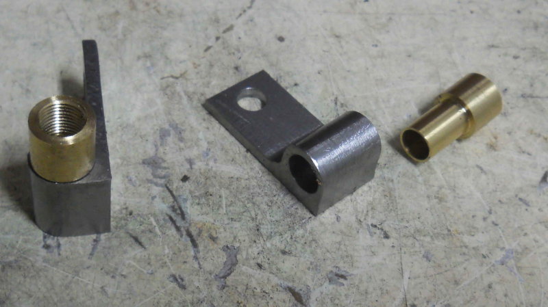
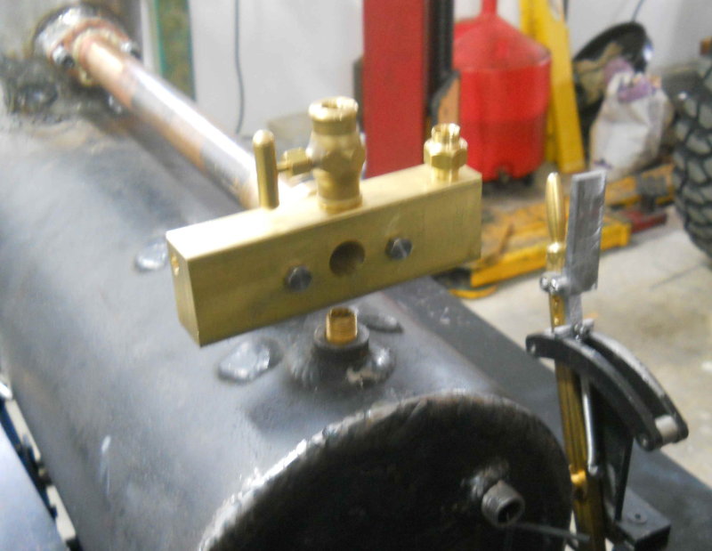
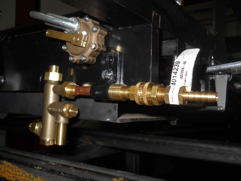
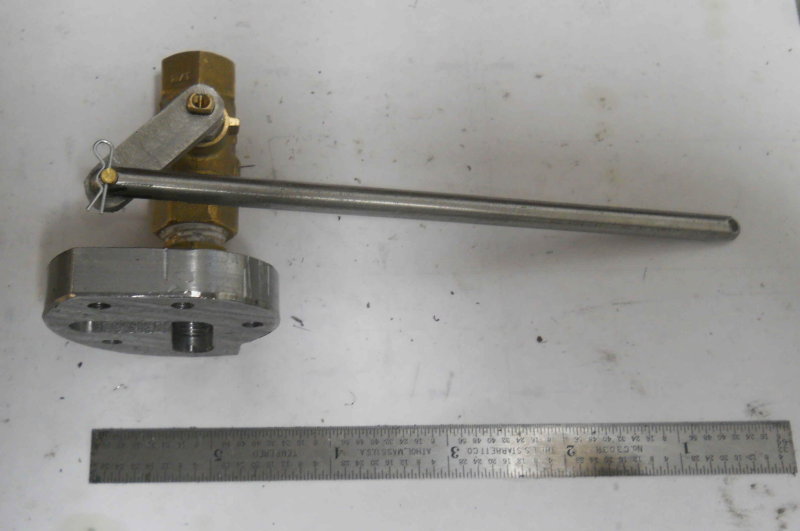
Some more halting progress. Made the first part of the 2-piece throttle reach rod from 1/4" 303 stainless, then a brass pin to connect it to the valve spindle crank. The assembly is retained by a small stainless latch pin as show in the pic. The through hole in the brass was drilled with a #56 drill, the smallest hole I can ever remember drilling.

large.jpg


While not visible in the photo, each end of the rod was milled flat half way through the diameter to provide a better mating surface.

The second part of the rod will be identical to the first, except its length will be determined by the size and position of the turret when made.
 
Last edited:
Thanks to a friend from our club, my steam dome is now welded up on the boiler.

large.jpg


I need to grind the welds and paint. With the flange mount for the throttle tube, I'll have some trouble with a dome cover, but I do have a few ideas that way.

I also bought material to make a rolling stand for the loco and tender, mainly 1" square thick wall tube. Started by welding up the pads for the casters. Not pretty welds, but they should hold together.

large.jpg
 
Got the throttle pipe and flange silver soldered together this week using the large oxy-a torch at the club. Now I need to determine the length of the tube and solder another flange on the other end to connect to the turret.

In the meantime, I did a bit more on the rolling stand, welding the lengthwise parts of the base and bolting on the 4" casters:

large.jpg


The long span won't support a huge amount of weight without bending, so there will need to be some "trussing" to make everything solid, even though the loco and tender together will weigh less than 300 lbs. Cleaned out the truck bed this afternoon, so I can mount the carry board and measure the height of the rails on the truck. Then will shoot for the same height with the stand.
 
More work on the rolling stand, which is now a monorail. My material calculations were off by one stick of 1" tube. Should get another later this week. Found out that I was not cut out to be a welder.

large.jpg


My order from Locoparts came in this week, including the water glass, so I'll need to locate/drill/tap the backhead, always a nerve-wracking task.
 
Finished up welding the stand, and moved the loco and tender chassis onto it:

large.jpg


Now a better measurement of the total connected length shows that they will just fit on my truck carry board without hitting the truck toolbox. Even with the tender on the stand, the 8' rail length allows over a full turn of the drivers.

I also drilled the hole for the water gauge in the boiler backhead. Wanting to make a straight hole, I came up with the idea of super-gluing a drill bushing onto the backhead. Good idea in theory, but the bond was not strong enough to hold once I started drilling. However, by keeping the bushing on the drill and against the backhead using magnets, the hole looks to be pretty damn perpendicular. Now if only I can find my 1/8 NPT tap.

I located the hold by measuring the top of the crownsheet through the top bushing, and then drew a line across using a sharpie. Then a second line at the level that made the bottom of the glass 1/2" above the first line. Finally over the left so that the fire door won't hit the gauge.

large.jpg
 
The casters are 2' apart, and it's very stable (and pretty heavy). With the two chassis mounted, the whole thing is 300+ pounds. The design is such that there are no sheer forces on any welds. I measured the rails with a digital level and they are within 1 degree of level. I intentionally made the center supports 1/8" shorter then the ends and clamped down to weld them. So any tendency to roll will be towards the center.
 
Got the backhead tapped for the water gauge and mounted it for a look see. Also cut gaskets for the throttle tube and the top for the dome, and did a trial fit.

large.jpg


I originally planned the two bushing on the top for the turret and the water gauge, but now that the throttle pipe will be attached to the turret and under steam pressure, I have one for a different purpose. Might make sense to use one for the pressure gauge rather then attaching it to the turret.

I made this adapter from some 9/16 hex brass bar. 1/8-NPT male on one end and counterbored 5/16 on the other. This will be used to connect 5/16 tube to the elbow for the water glass. Took less than 15 minutes to make on the lathe. Seems I can save a few $ making this type of fitting vs. buying at the hardware store.

medium.jpg


I don't have any suitable material for making the turret as yet. Looking for some brass 1.5" square bar about 4" long.

I ordered some 5/16 straight copper tube that will be used for the blower line inside the hollow boiler stay, and a coil of 5/16 tube for the rest of the piping from Mcmaster. Seems to me I could start by doing the water feed from planned quick disconnects (to be purchased) to the injectors and thence to the boiler check valves. The rest will need to wait until I can make the turret.
 
Last edited:
Having sourced a pair of Parker quick-disconnect couplings for the tender water supply hoses, I set out today to make the brackets that attach these to the frame. Kozo specified two different lengths (p. 193, drawing 33-11), but seeing no real reason for this I made both the same as the right side dimensions.

The first step was using the CNC mill to drill the holes and mill the profiles. Stock is CRS 1.25x1x2.5".

large.jpg


The two sides are mirror images as the rear of the brackets are to be tapped 1/8NPT, and the front soldered to 5/16 tube.

Next to the BP to tap one side. I really like the spring-loaded tapping follower; ensures the tap goes in straight.

large.jpg


Then I cut the two pieces apart on the bandsaw and then milled off the remaining bottom stock, and drilled the mounting hole for the 1/4' screw.

large.jpg


The brackets are mounted using the rear screw that also fastens the grill support rails. On the left side, there's nothing to get in the way:

large.jpg


On the right side the ash pan latch will be directly below the coupling with the brake pedal directly above, but it looks as if it should be OK.

My tender outlets are threaded 1/4NPT, so I'll need two different sets of hose barbs. I'll probably use 1/4" ID hose.
 
Being warned that my steel brackets are liable to rust and foul the injectors, I came up with a plan to save the day. I drilled/reamed the brackets to .368 (T size), then turned/drilled/tapped these sleeves from some brass rod. The sleeves will be soldered to the copper tube as well as the brackets.

large.jpg
 
First part of 2013.

There was a nice NYE getogether at the club, where I picked a few members' brains on soldering the piping. Seems the black flux needs too high a temperature for soldering copper/brass tube using the silver-bearing solder; I need zinc chloride. I looked it up on the net, and hunted for a local source. Seems I might want "Rubyfluid liquid", that should be available at a hardware store not too far away. We'll see tomorrow. I'll also need some 1/8" copper tube for the siphon and piping the lubricator. I'll have a lookout for that too.

In the meantime, since everything is closed on Jan 1, and it was raining all day, it was a good day for shop time. I made this coupling for the pressure gauge and siphon. I bought the gauge online from a fellow steamer, so hopefully it will work properly. It's threaded 1/4NPT, so my coupling is tapped to match and drilled though 1/8" for the siphon tube.

large.jpg
 
Kvom---Happy New Years!!! I can't even imagine the magnitude of the project you have underway there. You have been a faithfull poster over the past year, and shown some very high quality work and some good machining tips. Thank you for taking the time to do all this and post it on the forum---Brian Rupnow
 
First part of 2013.

There was a nice NYE getogether at the club, where I picked a few members' brains on soldering the piping. Seems the black flux needs too high a temperature for soldering copper/brass tube using the silver-bearing solder;

Kvom

This is what you need; its also good for stainless so a one stop shop for a silver solder flux. Apparently similar to the JM Tenacity #5

StaySilvBlack.jpg


http://www.harrisproductsgroup.com/en/Products/Alloys/Brazing/Fluxes/Stay-Silv-Black-Flux.aspx

Pete
 
Got in some fittings from McMaster, so made a start on the tender water piping. Screwed in these elbows (1/4NPT to 5/16 compression, and after placing the tank onto the frame discovered that the end of the compression fitting is about an inch too high, so that the front of the tender frame blocks it. So I'll need a coupling of some sort to lower it. A simple straight barb wouldn't work as the supply tube would hit the wheels. Same problem with turning the elbows to face inwards.

large.jpg


I also found a 6' coil of 1/8 copper tube with some fittings for sale at Autozone (brand name Sunpro). The fittings allow 1/8NPT male or female, so I plan to use these for the siphon rather than soldering. My tubing cutter is too large to cut this, and a coping saw doesn't work much better. Found I coud cut it cleaner with scissors.

I also wanted to replace the brake assembly on the chassis, only to find that the rails get in the way. The only way to install them is from the bottom with the drivers in the air.

Ordered a chunk of brass to make the turret, so if I can get that build I can get serious on the piping.
 
After a couple of weeks away from home, I spent an afternoon in the shop with the A3. Propped the loco frame on some riser blocks to get the wheels off the rails, and was able to mount the brake assembly. Everything is a tight fit, so not too easy. Anyone who builds the brakes and is ready for a final assembly will be advised to install them before any valve gear or rods.

Next I re-installed three of the spring packs. The springs are quite strong, so I found the best way to do the rear pair was to install them on the hangers with one hanger unattached to the frame. Then I could press down enough to start the screws for the other hanger and let the screws compress the springs. I also found that installing the back hangers for the front drivers was a real PITA. The drivers keep you from inserting the lower pins from the outside, so I had to finagle installing the tiny e-clips using needle nose pliers and strong language. These hangers should be mad and installed early in the assembly process, before the drivers and axles. Got one spring pack on and found that one of the retainer clips for the other is missing. So that's a little fab job for tomorrow. With the springs installed I'll be able to put on the boiler and smokebox to start laying out the piping.
 
I got the springs mounted and then put on the boiler and smoke box. With that weight the axle boxes are close to the center of the their travel range, which seems likely is the design point. Here's a pic afterwards:

large.jpg


The fact that the boiler drawing put the steam dome 2" too far forward is going to make the loco look mis-proportioned, even with the sand dome moved forward as shown. The bell will end up very close to the smoke box. The throttle tube is higher and thicker than Kozo's drawing, so I'll need to modify the front wall of the cab to fit eventually.

In any case the club boiler hydro-tests are next month; since I've now drilled all the holes into the boiler that are needed I'll be ready for steam-up afterwards if I can get the piping done.
 
Last edited:
I made a start on the turret today. The body of the turret is a piece of 360 brass, 3/4x1.25x4". Drilled the two holes for mounting to the throttle tube and drilled/reamed the 1/2" center hole for the throttle rod gland. My design for the gland derives from that used for the valve rods, using a Viton o-ring for sealing the 1/4" SS throttle rod. The gland itself is two-piece, the larger brass piece fitting into the turret hole and the smaller bronze piece fitting the larger. The two pieces leave a pocket for the o-ring. This design will allow me to remove/install the 2-piece throttle rod and the valve crank without removing the turret itself.

large.jpg


With the parts assembled, the back view:

large.jpg


This view of the front shows how the cross-drilled hole will intersect the main steam passage to supply the injectors while missing the mounting holes. Any other valve holes will intersect the cross passage.

large.jpg
 
Today I drilled the cross passage in the turrent without a problem, using a C drill bit from each end (C is the tap drill for 1/16 NPT). Then I assembled the turret block and rear flange on the loco for a test fit (the rear flange needs to be marked on the throttle tube before soldering so that the turret is horizontal).

large.jpg


Then I discovered a problem: The right end of the turret is even with the reversing lever when at full forward, and there's not enough room for the injector valve and a pipe union. I'll have to decide what to do about that.
 
Did a few minor tasks in the shop today. I had to take the boiler and smokebox off the chassis as I need to remove the rear footplate. It will need to be counterbored for the drawbar pin as the head of the pin interferes with the fire door. I attached the brake pedal and reach rod in order to get an idea of how I'd mount the injector at the rear of the frame. There's a lot of "stuff" in that area: blowdown valve, ashpan latch, and the foot pedal. Looks like it will just fit without being too far forward. I don't want it too close to the rear driver as that would mean a sharp curve in the water supply pipe.

I did a test fit on the left side, where there is nothing to interfere but the blowdown valve. With the valve clamped to the frame in its approximate position, I ended up with this:

large.jpg


I drilled a second hole in the bracket to move it higher, as shown. The bottom of the injector is still only about an inch above the rails. I'll probably try a bit of an s-curve on the copper tube to position the injector a bit higher.
 
Back
Top