ET Westbury Side Paddle Engine

Home Model Engine Machinist Forum

Help Support Home Model Engine Machinist Forum:

This site may earn a commission from merchant affiliate links, including eBay, Amazon, and others.
Hi kvom,good to see you back on the paddle engine,we had a race going at one stage,i guess i won 😛.
The way i did the timing was to hold the sheaf on to the eccentric without the back half in place,set the timing lock the set screw and replace the back bit,worked ok
Don
 
I learned a few things when doing the partial/test assembly. One is that my frames are fairly flexible, and with no support at the bottom it's easy to cause the cranks to bind. So before too long I need to come up with a base to anchor them.
 
Spent weekend shop time working on the steam chests starting with the CI bar; First, cut off two slides with the bandsaw and face them both sides on the lathe. Both end up at .82" thick. Drilled a half inch hole for swarf "drainage" when pocketing.

large.jpg


CNC operations:

large.jpg


For the outer profile I used one of the steam chest covers as a fixture:

large.jpg


Then to the Bridgeport to bring both to .75" thickness. This allows the valve rod to be in the center and thus both chests identical:

large.jpg


Then back to the CNC mill to mill the boss and drill/ream the center hole:

large.jpg


Back to the Bridgeport where I used a long center drill to locate the rear hole for the guide, and then drilled the through hole 1/8". All was well on the first, but had a disaster on the second when the drill apparently jammed and broke.

large.jpg


The end of the drill is inside only about 1/8". But it has resisted attempts to press it out with vise and arbor press. I tried heating with a propane torch, but that didn't help. Also tried milling it out with a carbide EM, which broke, but the one I weas using was too long; might be worth risking another tomorrow.
 
Hi kvom
Try to grind that stuck piece with a Dremel or similar tool, at the highest speed. Make it a hollow piece, than you can break it and remove the parts from your workpiece.
BTW: GREAT WORK so far!
Regards
Gerhard
 
I got it out by pushing it backwards. Piece of steel through the cavity against the drill, and two other pieces of steel against the vise jaws, and it popped loose without much force.
 
I'm glad I'm not the only one breaking drills. :D great work so far. I'm in the process of machining the steam chests at the moment. Pics later today.
 
Back at it to finish the steam chests this morning.

As before, the end guide is a 14/20 thread, and the packing gland 5/16-24. The steam supply hole is 5/16-27 NPT (1/16 pipe).

large.jpg


Remake of the guide bar brackets started with some brass bar. CNC machined the profile, and then finished to size of the Bridgeport.

large.jpg


To cut the slots for the bars I used a 1/4" Woodruff cutter. Started by touching off:

large.jpg


Then adjust height and depth to mill the slots.

large.jpg.


Drilled the top and bottom clearance holes for attaching the bars, but the holes for frame mounting need to wait for fitting.
 
A "fettling day" here. First task was to make three spreader bars, all the same length +/- a couple of thou, in order to stiffen the frame assembly. These allow me to work on one of the engines by itself more conveniently.

large.jpg


Then I spent several hours adjusting and trimming the crosshead assemblies, ending with these:

large.jpg


All of the dimensions given by Westbury are zero clearance, so any moving parts will need to be adjusted. One thing that doesn't show in the plans is a small notch needed near the upper inside guide bar that allows the inner cheek of the crosshead to pass the bracket.

Anyone else building this engine will be well advised to get this assembly moving freely before mounting on the engine as a whole. Note the bevels on the ends of the guide bars. These are not decorative but as needed to clearance the conrod at its maximum angle.
 
Back in the shop after 4 days away from home. More adjustments/filing/etc and the piston-conrod-crank assembly now moves freely. Then I started to work on the 2 eccentric sheaves I'd started years back. After facing the cut-off sides, I mounted them on the Bridgeport. After center finding, I used the sport drill to scribe a line down the center to aid in drilling the holes for the setscrew. Then drilled and reamed the crank hole.

large.jpg


Next I could use the scribed line to set the part vertical in the vise.

large.jpg


Drilled and tapped 8-32, as I have setscrews that size. I'll have to shorten them here. The assembly as it sits:

large.jpg
 
Lovely work! I particularly like the idea of scribing a datum to ensure you get the setscrew central. I would never have thought of that ...
 
Had a couple of more afternoons in the shop working on the engine. Here's where it was at the start of today.

large.jpg


To fasten the valve parts together I needed to make the "pivot pins" from some 1/4" drill rod. Pivot shaft is 1/8" and threaded end is 4-40. Drill rod is rather sticky when turned, but that's all I had to work with. After turning the threaded end to .112" I used a little die I've never used before, mainly because I don't have a diestock that size. But I succeeded by keeping the die square with the tailstock and turning it with a wrench.

large.jpg


large.jpg


With a couple in place:

large.jpg


The shaft for attaching the lifting link is similar. I made it 1/16" longer than the plans to clear the pivot pins a bit better. It's a press fit in the eccentric strap.

large.jpg


Final job of the day was to make the die blocks, a CNC task.

large.jpg
 
Looking good
Don
 
A few more parts done today, including the weigh shaft links:

large.jpg


Along with the weigh shaft, a test assembly of one of the engines:

large.jpg


At this point, I have all of the parts needed to try to get a runner of this engine. Before trying to run it, I need to disassemble and drill all the oil holes I've heretofore ignored. The valve rod is also a bit sticky.
 
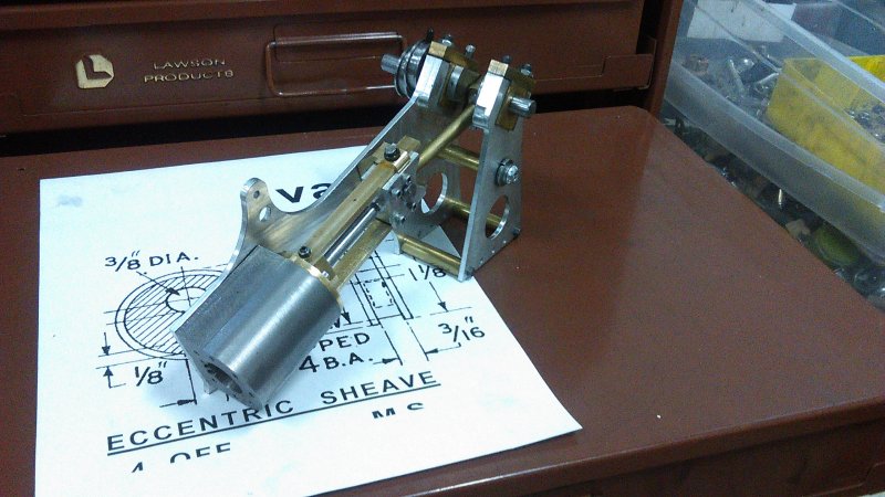
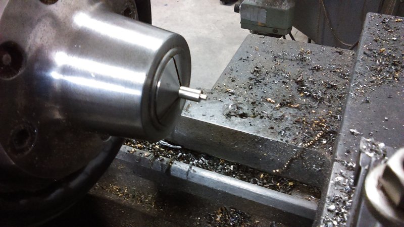
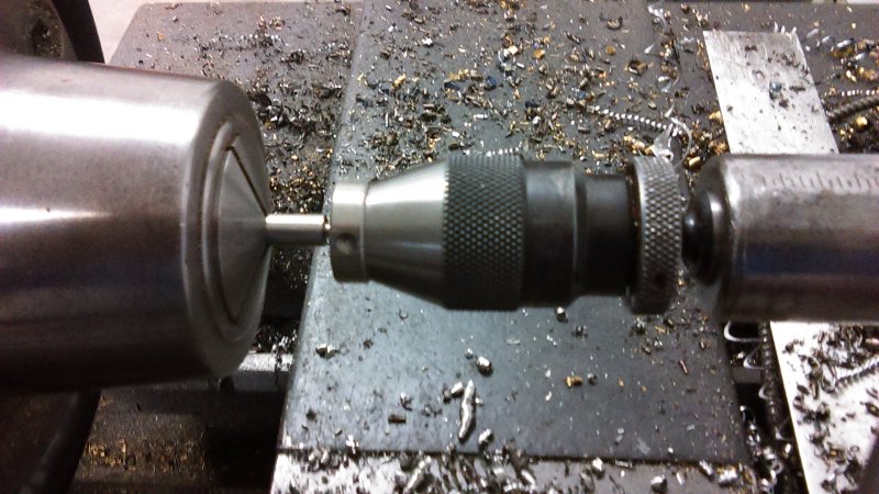
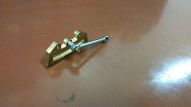
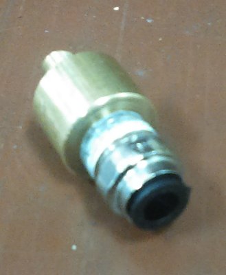
The trial run did not go as well as hoped. I had tapped the steam delivery line as 1/16-NPT and bought push-to-connect fasteners that take 1/8" OD tubing. I was not able to find such small tubing at my local store, so have placed an order with McMaster. In the meantime, I decided to use the 1/4 NPT fasteners used for the Joy engine, so made an adapter from .75" diameter brass rod, 1/4-NPT female to 1/16-NPT male:

medium.jpg


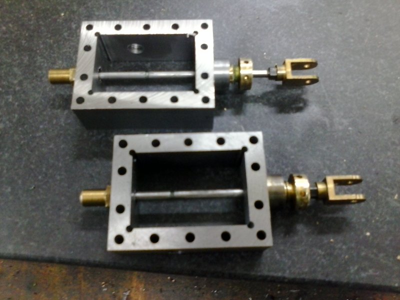
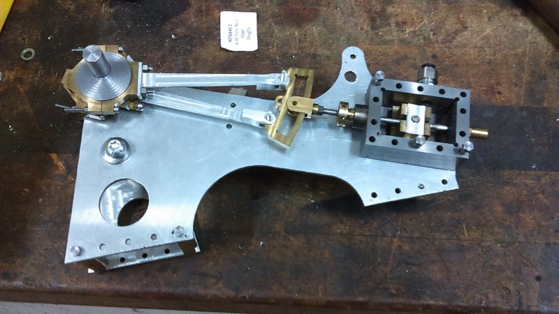
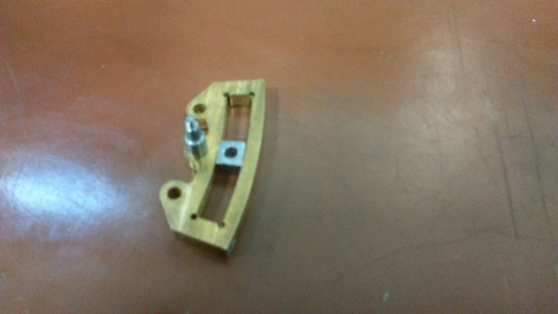
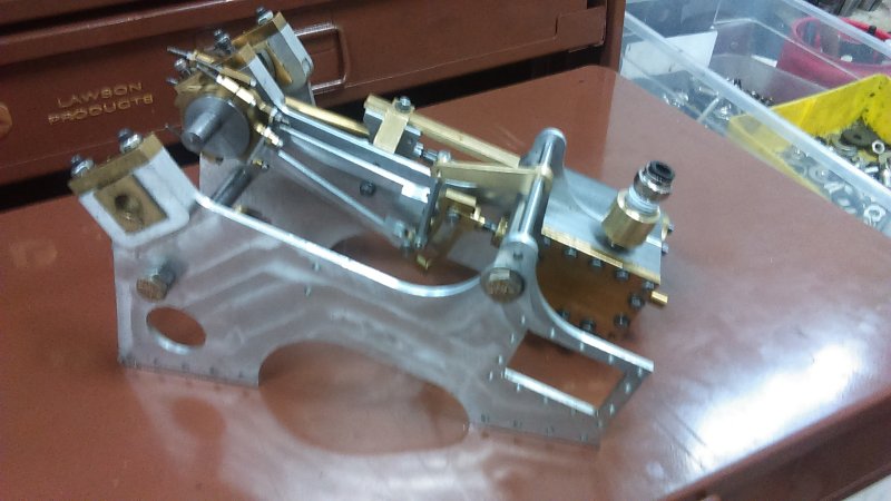
With this screwed into the steam chest:

large.jpg


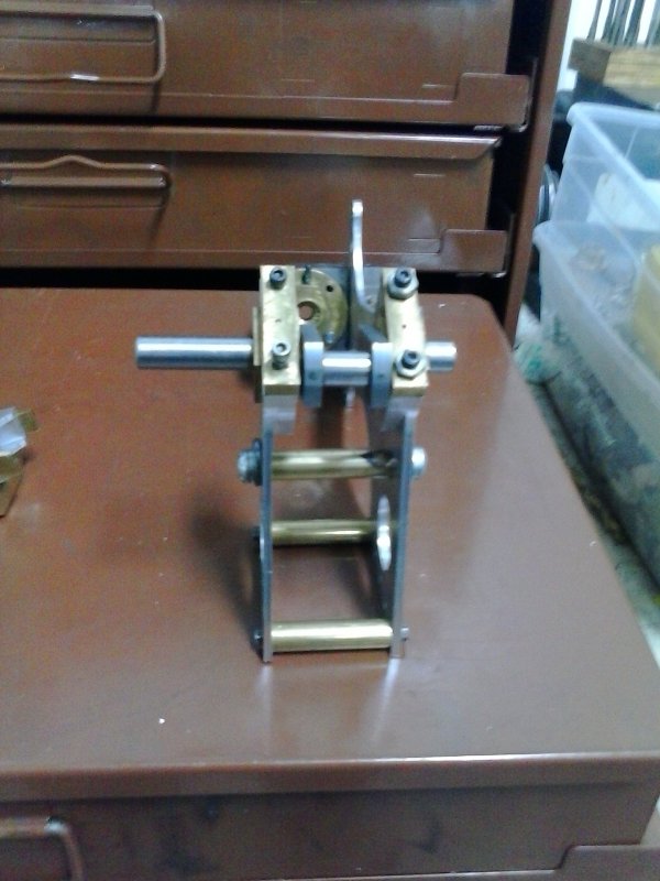
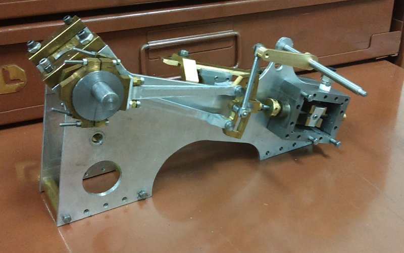
Applying air produced no inclination for motion to occur (I had a drill chuck clamped to the crank for momentum and turning by hand). I did feel some resistance when turning, but not a lot). When I increased air pressure to 30 psi the crank resisted turning in either direction.

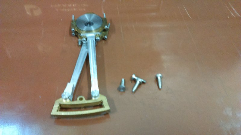
Can someone refer me to a good web page for describing timing a Stephenson? What I did, with the cover off, is set the eccentrics so that when the piston was at its maximum backward position the back steam port was open, and then when at the maximum forward position (closest to the crank) the forward port is open. I didn't try to make valve particularly centered.

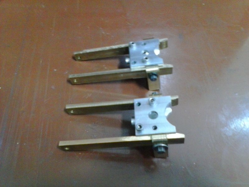
Since I don't have a way as yet to lock the weigh shaft or weigh arms, the weight of the eccentric trap keeps it down to that the direction controlled by the upper eccentric arm is in control. I'm considering removing the other eccentric temporarily until it runs in one direction, but don't know if both are needed for proper operation.

Given that I didn't have any gaskets or packing, there were surprisingly few air leaks.
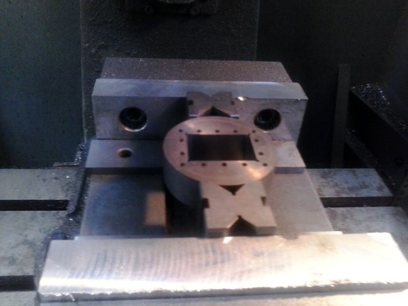
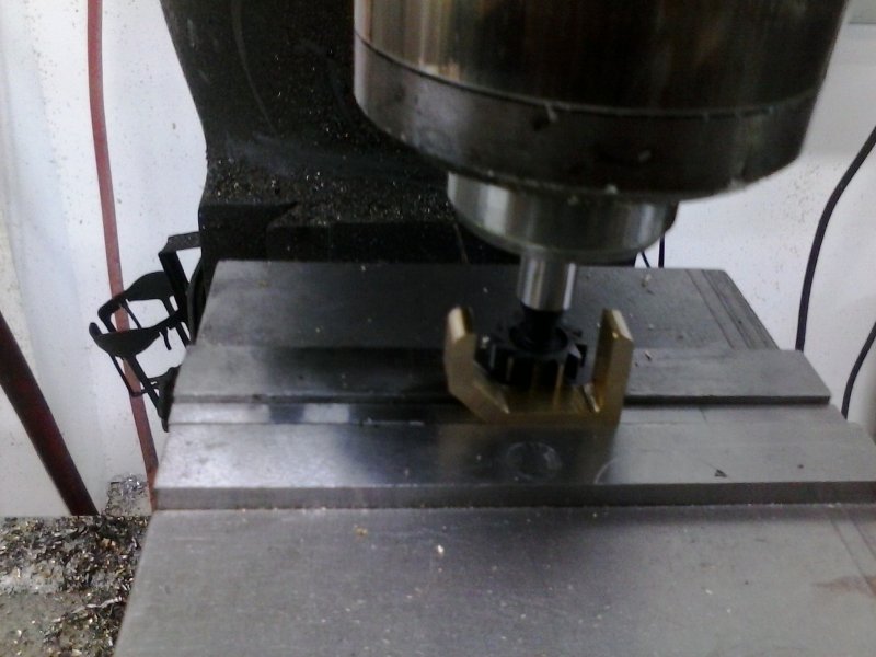
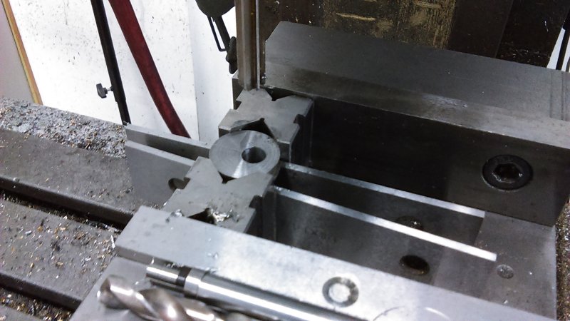
 
The way i time the valves is to get the valve to be equal each end of its travel then when the piston is near the end of its travel the valve should be just cracking open to admit steam to that end of the piston,
That has always worked for me,hope it helps.
Don
 
The valve should crack open as the piston just before top dead centre,as i said
 
JasonB ever on MEM got be straightened out on eccentric settings, but now I found that I bent the valve rod. So will be making another and trying another run.
 
Good luck. I'm following right behind you and learning heaps.
 
Herb, you might want to consider temporary "staybolts" between the feet of the frames, as opposed to leaving them on the base. I found it quite useful to be able to turn the assemblies around in various directions and to get access from below.

I tried another run today without success after setting the eccentrics according to Jo's diagram. No luck, and the valve motion didn't look right anyway. I remade the valve rod and opened up the tail guide on the steam chest, so the rod motion is smooth. I intend to make some additional lower staybolts between the two inner frames, as I discovered that the cylinder end of the frame was flexing a bit when I turn the crank. As can be seen from the last pic both inner frames are necessary to support the weigh shaft.

The separation of the two engines is quite arbitrary, and can be adjusted to the width or configuration of the boat to be driven. Places call for 2.75".
 

Latest posts

Back
Top