Upshur's opposed twin engine

Home Model Engine Machinist Forum

Help Support Home Model Engine Machinist Forum:

This site may earn a commission from merchant affiliate links, including eBay, Amazon, and others.
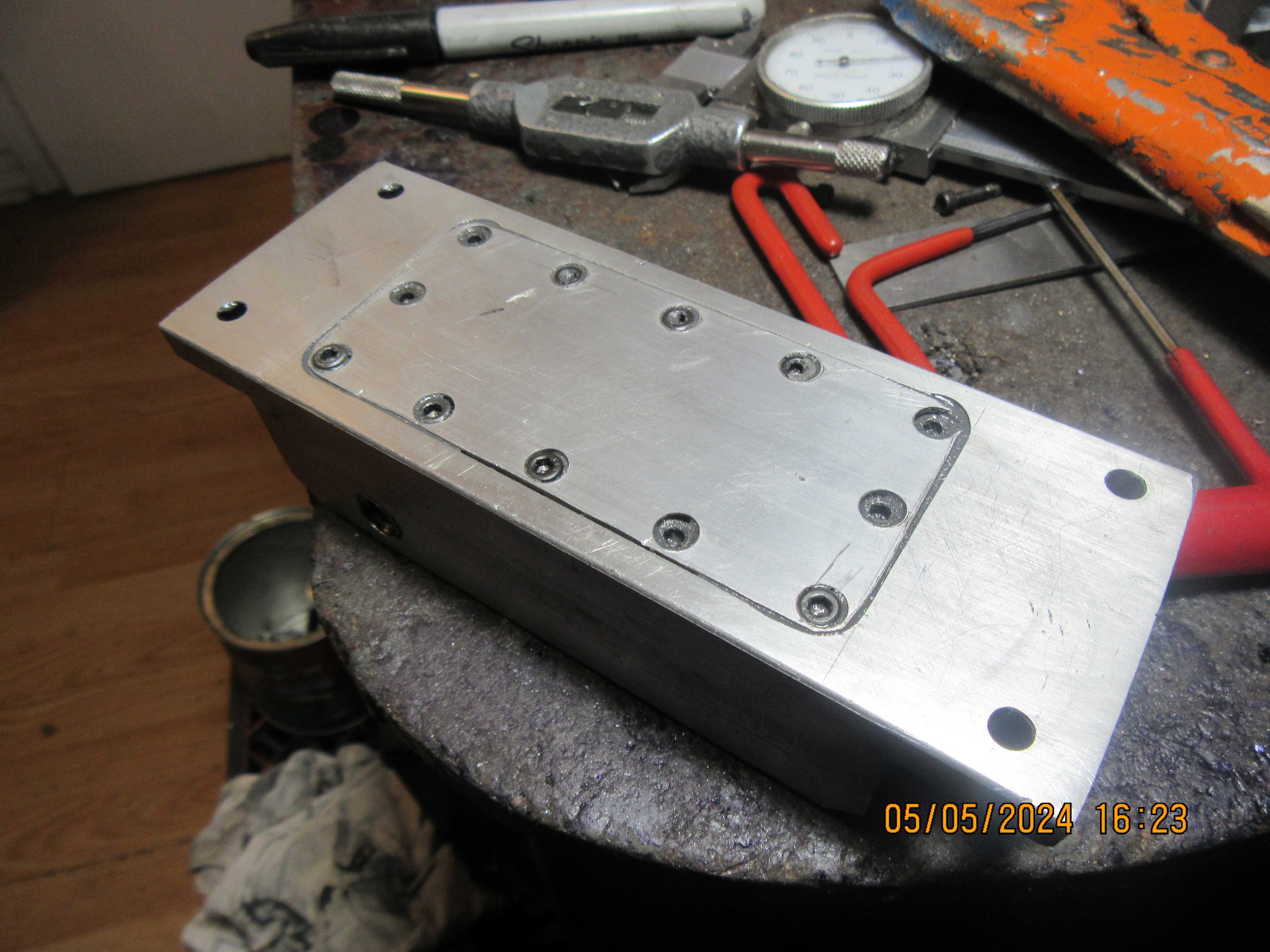
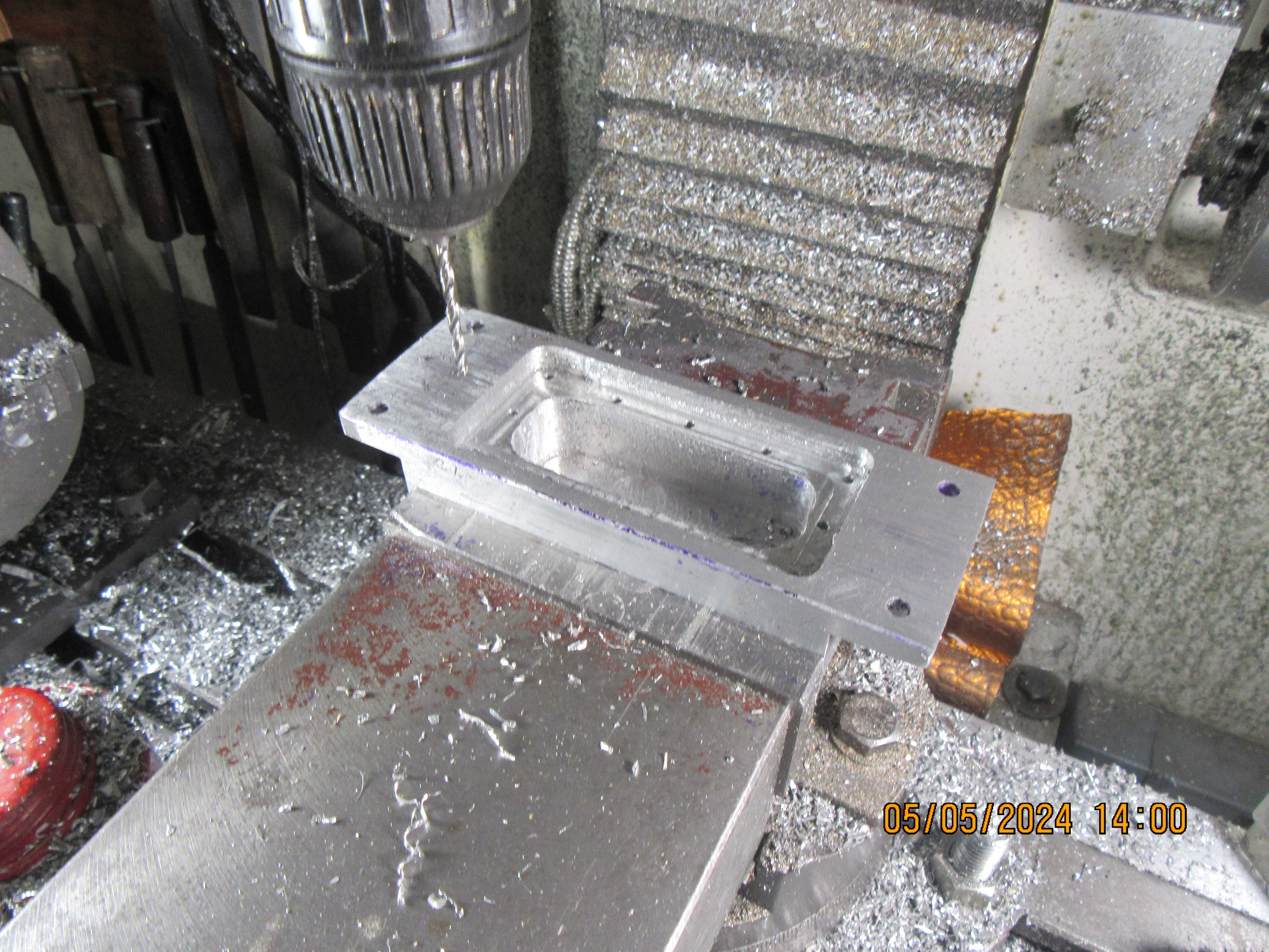
Today, the engine sub base became a gas tank. Not a lot to say about it---a lot of hogging out on the mill, a cover plate drilled and counterbored to fit, and a bead of J.B. Weld all around before the screws were tightened up.
OuEKZm.jpg

3oARgV.jpg
 
if you can't get a Helicoil maybe you could make an insert with an internal thread 1/4x32 and an external thread of what ever you have
drill and tape the head for the insert and then screw the plug into that, just a thought


EDIT: I missed the rest of the post sorry disregard
 
1 gas tank. How many buckets of swarf? - What fun you must have had with that one!
I spent a few hours yesterday teaching 2 "apprentices" (Both retired) all about steaming - "good practice" as I apply what I know - and 2 Boiler inspectors and an experienced loco engineer joined-in and added a couple of extra "tips". We all learned something in sharing that knowledge.
We also certified a steam test, and confirmed the boiler burner (as calculated) was inadequate for the steam turbine that is fitted as the load on the boiler.
All in all simply "fun" - but not machining. - Next a new design of burner for the Club shared boiler...
I must find time for my own projects...
How do you manage it Brian?
K2
 
Steamchick--I have very little going on in the rest of my life. I spend my time either reading for entertainment or working in my shop.---and occasionally taking good wife out for a meal.---Brian
 
I can get gas into my gas tank, and I can get gas out again. Thats all, to nice outside to spend any more time in my shop today.!!!
mbTHaA.jpg

L6sWcb.jpg
 
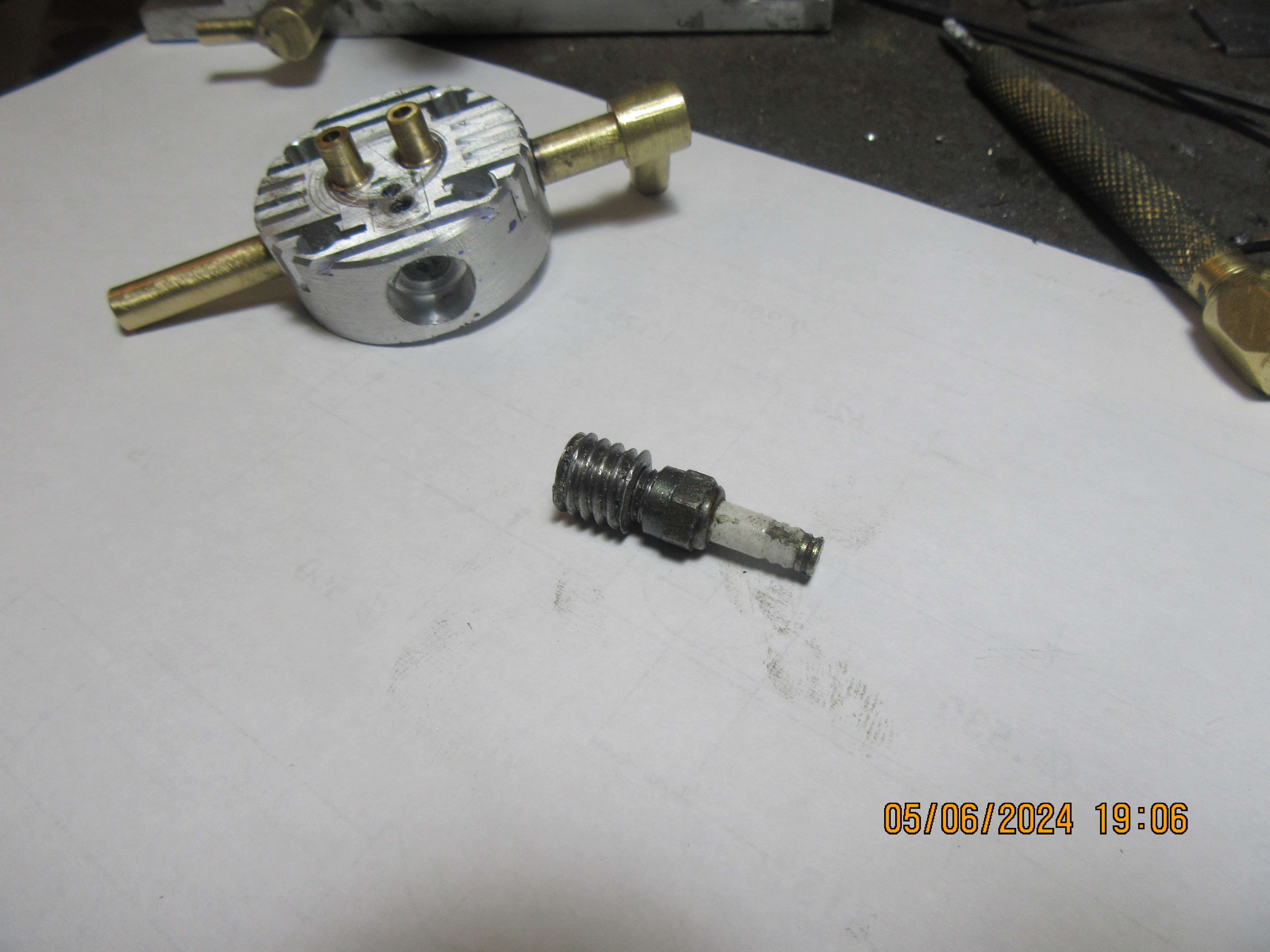
The sparkplug thread repair is under way. What you are looking at is a piece of steel threaded 3/8"-16 unc on the outer diameter and 1/4"-32 on the inside diameter. The sparkplug screws into it just fine. Now the question is "Will I be able to tap a 3/8"-16 unc thread into the aluminum cylinder head to accept my home made insert." I may have to cut off a 3/8" tap to get the threads into the bottom of the hole. I would have used a 3/8" fine thread on the outside, but I only have one 3/8" fine thread tap, while I have about six 3/8" coarse thread taps.---More to follow.
ZmnRvI.jpg
 
Hi Brian, I like your simple life. I aspire to that myself... Just too many other things get in the way of the modelling. Next is refitting the conservatory roof where it was removed for scaffolding for....
Then varnishing the wood where UV has destroyed the 10-year varnish... in 4 years...
And GARDENING. -
That's how it goes.
But I may do another silver soldering job and make a gas burner for someone, as those are quick fillers when I get a chance.
Hope the plug-job gets plugged!
K2
 
Pity you did not make the repair liek George said. With it still on the bar you can screw it in to check your thread depth and more importantly get it back out if your thread is not deep enough. As you have it it could get stuck and be very difficult to remove.

Also to give it half a chance a better thread would not go amiss, that one has chuncks out of it and the middle three threads look to have more cut off than the others as it looks smaller in the middle. Clean all the swarf and cutting oil out of the thread too to give the loctite a chance of bonding.

That insulator on the plug could also do with a clean so there is no risk of the spark tracking when it is firing in the engine where there is more chance of that happening even though it may look OK sparking outside the head.

plug.JPG
 
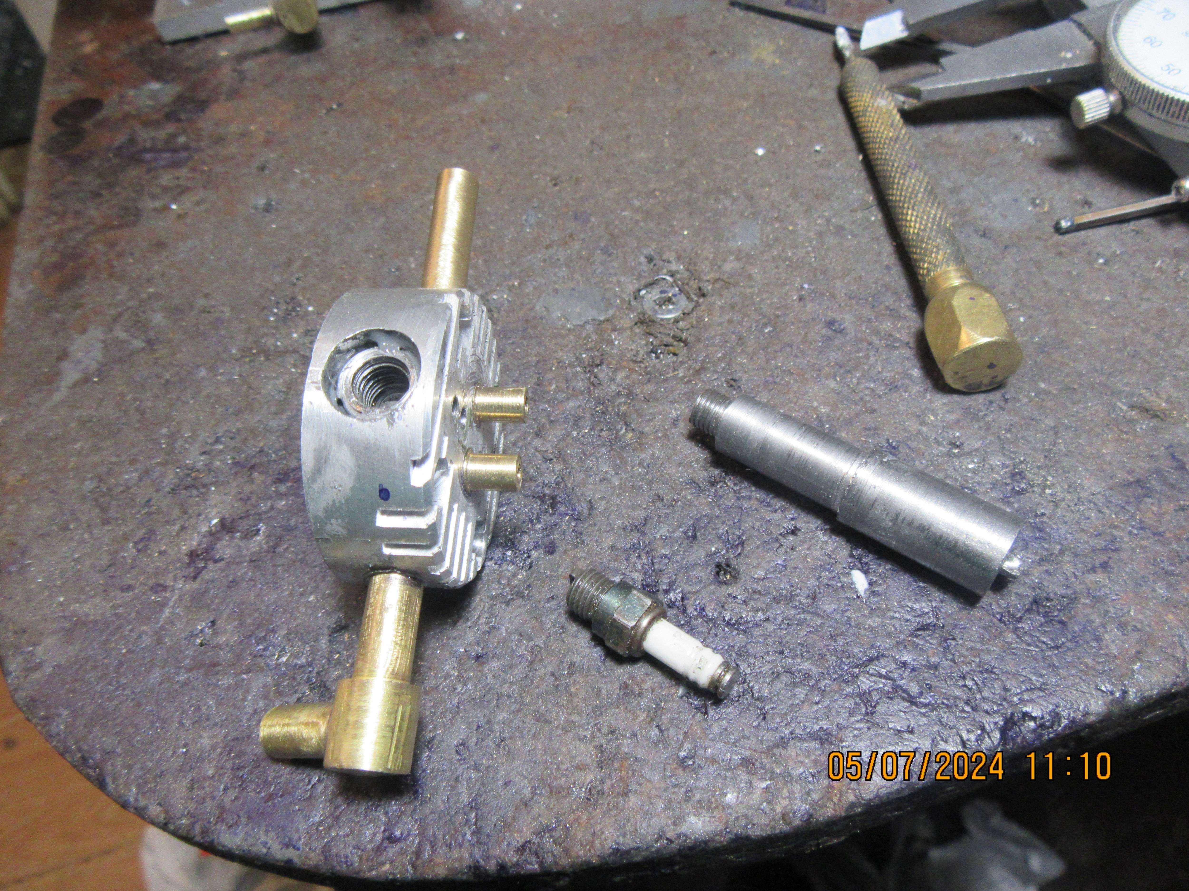
Okay, for what it's worth---The new threaded insert is in place. In the picture you can see a "driver" that I used to screw the insert into place after the aluminum cylinder head was threaded 3/8"-16 and the home made threaded insert was coated with J.B. Weld. Then the driver was unscrewed, while the insert stayed in place. So far, so good. So far, this hasn't cost me anything. Tomorrow I will finish this, after the J.B. Weld has dried for 24 hours.
jtcBoI.jpg
 
Good job Brian. It may be worth doing an ‘electrical’ resistance test, between the insert and the head, just to make sure that the JB weld hasn’t created any potential ‘insulation’ issues?
 
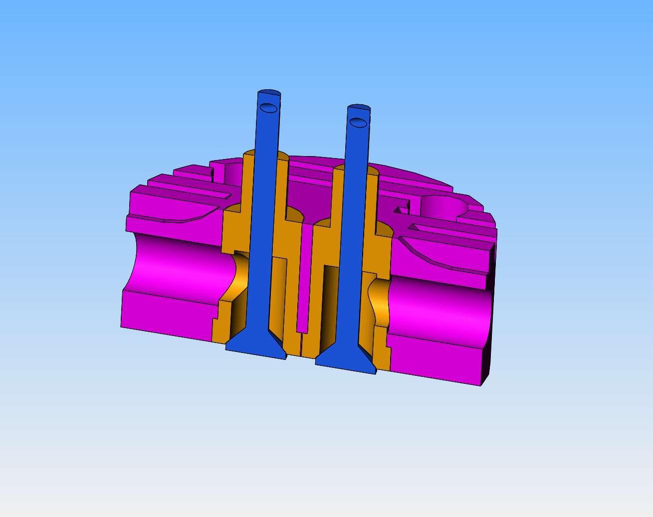
I've ran into a problem here with how well my valves seal---or not. Every previous engine I have built used full length "valve cages" in which the valve guide section and the sealing face were all turned from one piece of brass. This engine is designed differently, whereby the valve guides are made from a length of turned brass, but only in the area that guides the valve stem. The valve face seats against the aluminum head material.---I can't get my valves to seal this way. I have played with the design a bit, and found that I can save my existing heads by opening the holes a bit more and machining full length valve cages. I didn't really want to do this, but it seems to be a viable option and I have lots of brass. This will set my "finished" time back a bit, but won't really cost me anything but time.
HbGiTy.jpg
 
Cylinder heads have been re-bored to accept new full length valve guides. New valve guides have been fabricated and installed in cylinders after being coated of J.B. Weld. The new threaded insert I made for the sparkplug is installed in the cylinder head, and seems to work fine. Everything I touch right now seems to have J.B. Weld on it somewhere, so I'm going to wash my hands and go upstairs to read a book.
 
Brian, I wondered about the valve guides and creating the valve seat in the aluminum. The press in valve guides that I like are the ones on the Howell V-Twin. They incorporate the valve seat at the bottom of the valve guide. Dont forget to drill holes thru the new valve guides for the intake and exhaust :).
Jerry
Well, for sure if he forgets to drill the passages, he eliminates 2 out of 3 possibilities for no compression!! 🤣🤣🤣
 
Last edited:
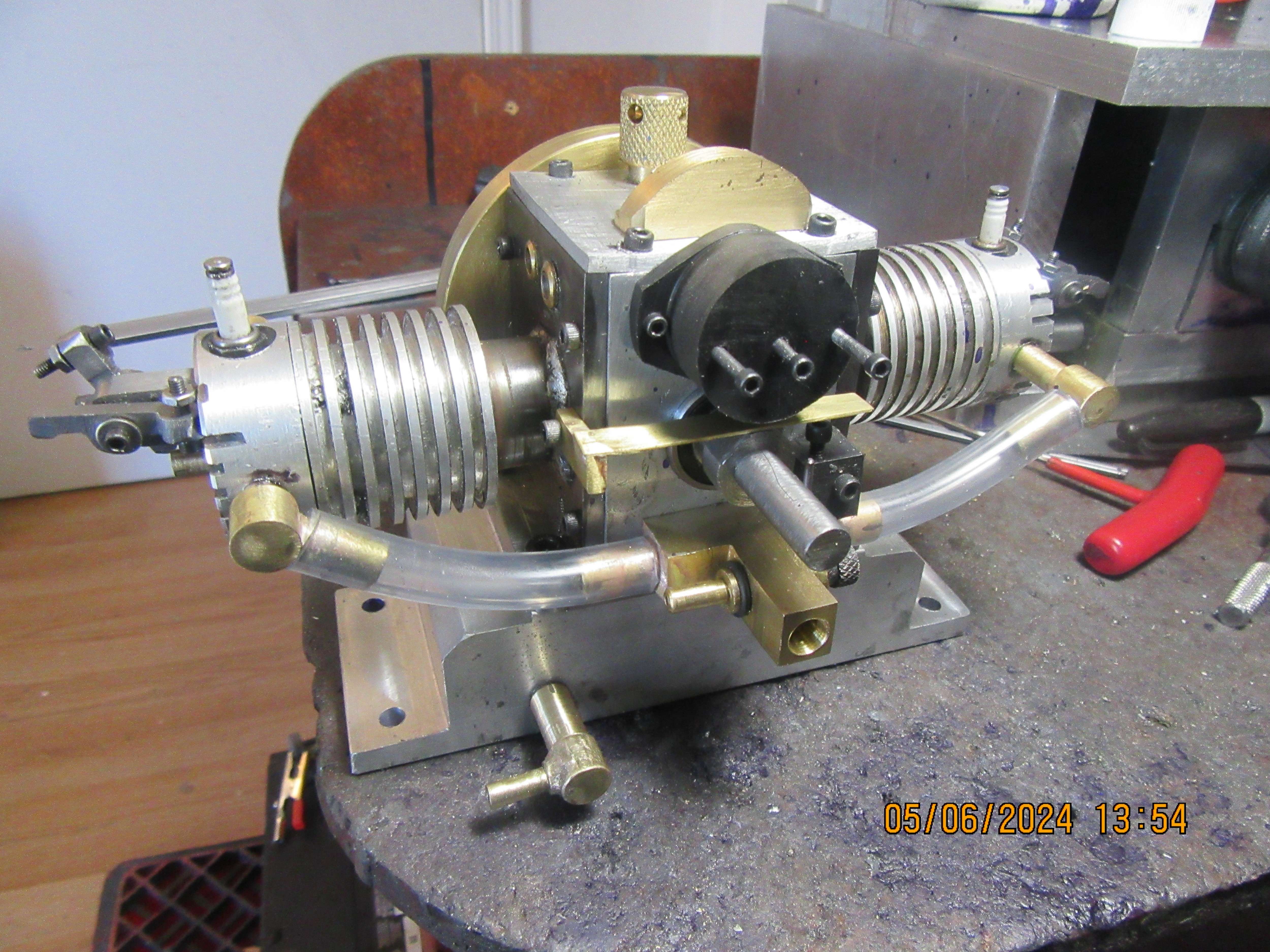
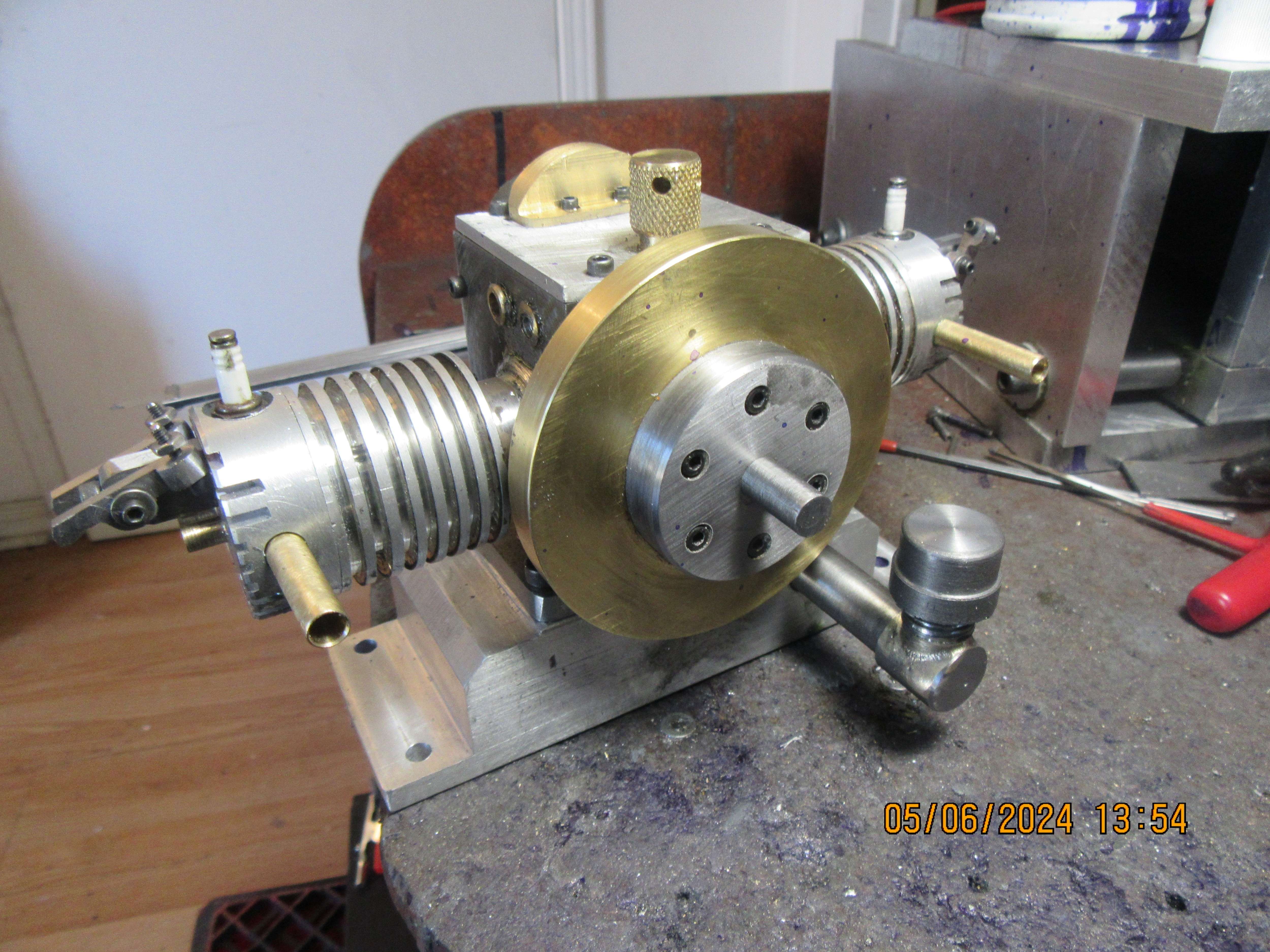
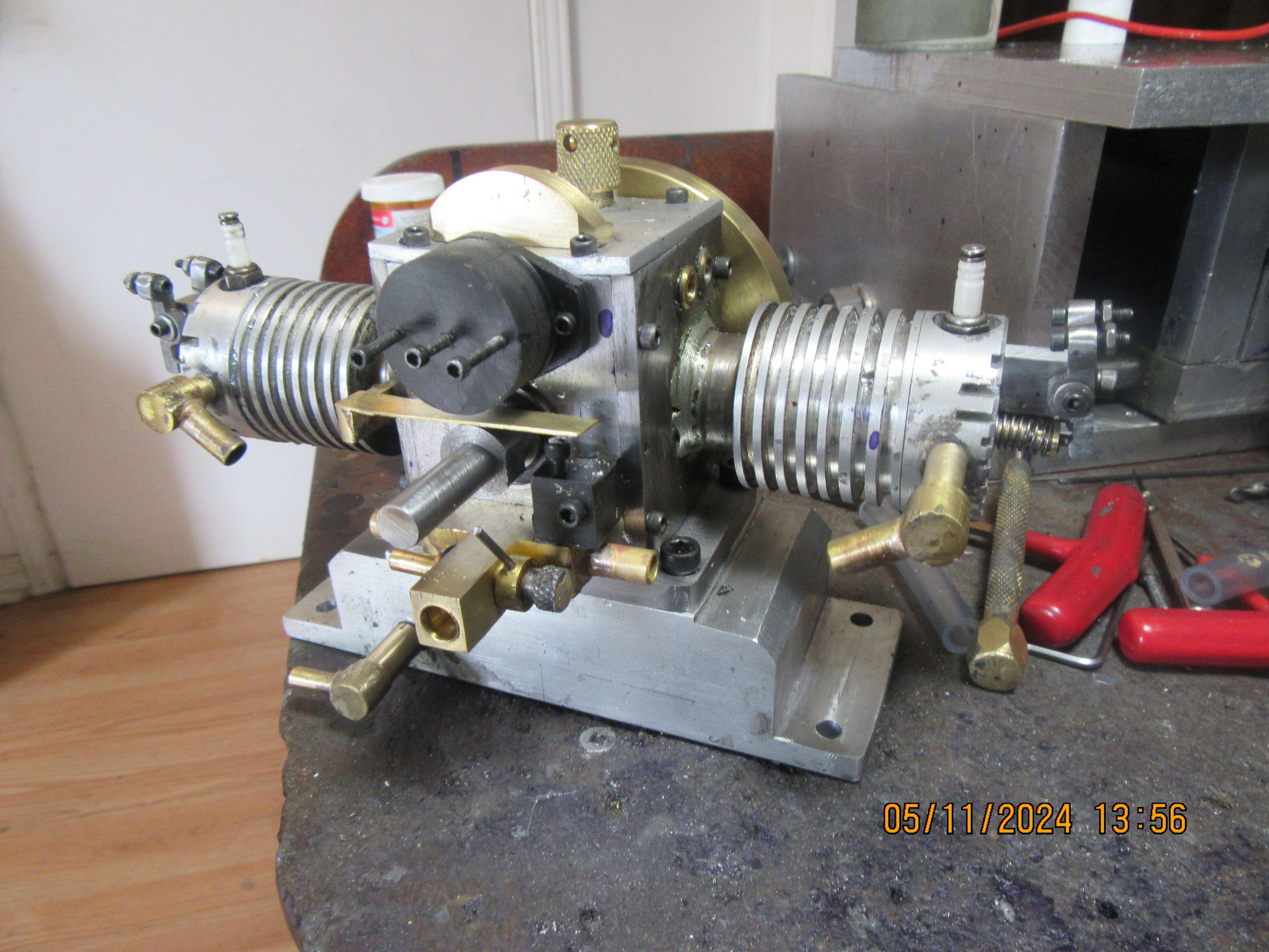
After a couple of days of "sluffing off" (which I enjoyed very much), I went back to work on the engine today. The valves had to all be reground to match the new valve cages. I was able to get a drill in thru the exhaust tubes to drill exhaust ports in the side of the new exhaust valve cages, but had to remove the inlet tubes because they had an elbow in them. The new intake ports were drilled thru the intake valve cages, and then the inlet elbows were reinstalled in the heads. I cut my intake and exhaust springs to length and cross drilled the ends of the valves for keeper pins, and assembled the valves, valve springs, and valve keepers and pin. Immediately, I discovered something a bit fishy---the cams have a total lift of 0.072", but there isn't enough room between the valve spring keepers and the valve cages to allow the valve to travel that far. I will remedy that by taking 0.030" off the length of the valve spring keepers and 0.030" off the height of the valve cages above the heads. The valve cams are made, but not installed yet. I think this finishes all the major machined pieces. I still have some small stuff like oil dippers and the copper strip that attaches to the ignition rotor to make.
Gd54EJ.jpg
 
Werowance--I have a set of store bought points that have been damaged, but the contact buttons on them are brand new. I would like to unsolder the contact buttons from their original point set and re-solder them to my brass strips and bolt head as per the Upshur plans. What kind of solder did you use when you did yours? I have silver solder and flux and I have a kit of "safe flo lead free plumbing solder" and flux from Oatey that flows at 415 degrees Farenheight.---Brian
 
Looks like the valve problem is due to you drilling the pin hole too far from the end of the valve. If done as drawing with an e-clip there should only be 0.050" of valve above the keeper, you look to have about double that which is putting the keeper too close to the cage. Same 50thou could have been retained when using a pin.

Position of your rocker does not look too good either

50thou.JPG
 
Werowance--I have a set of store bought points that have been damaged, but the contact buttons on them are brand new. I would like to unsolder the contact buttons from their original point set and re-solder them to my brass strips and bolt head as per the Upshur plans. What kind of solder did you use when you did yours? I have silver solder and flux and I have a kit of "safe flo lead free plumbing solder" and flux from Oatey that flows at 415 degrees Farenheight.---Brian
i just used plain old electronics solder. no flux or anything

edit - also do you have the capacitor thats needed to act as the condensor? i cant recall what the rating was but it was given to me by another member and it works realy well. small/compact and fits in the wiring with some heat shring tubing so you barely even see its there
 
Back
Top