
You are using an out of date browser. It may not display this or other websites correctly.
You should upgrade or use an alternative browser.
You should upgrade or use an alternative browser.
Building Rudy's Steam Tractor
- Thread starter 4156df
- Start date


Help Support Home Model Engine Machinist Forum:
This site may earn a commission from merchant affiliate
links, including eBay, Amazon, and others.
- Joined
- Jul 16, 2007
- Messages
- 2,987
- Reaction score
- 1,055
The boiler looks great Dennis. If you run into the situation again where you're concerned about the end cap moving when you start to solder it, just put a few punch marks around the O.D. of the cap and tap it in place. It won't go anywhere.
gbritnell
gbritnell
you have done a very good job there
the silver soldering part of the boiler seems very good to me, many here would be more than satisfied indeed
I must browse all the thread, surely it is as interesting as these last pages :bow:
--------------------------------
well, I looked the whole thread and I feel a bit of shame now, I had forgotten your wonderful build on this steam tractor...
at about half of the thread I replied too, but I never came back after that, so I miss your progress...
congrats for this great work and thanks for sharing it
and yes, you can teach to everybody how to silver solder :bow:
- Joined
- Feb 25, 2008
- Messages
- 464
- Reaction score
- 5
George, Your tip about using the center punch marks for holding position is a good one and one that I will be using. Thank you.
Arnold, Dean, Doug & Ariz...Thanks for the comments.
Post #40
Boiler (Contd.)
With all the soldering complete, its time to pressure test the boiler.
The safety valve pops at 30 psi and, according to other builders, the tractor operates at 15-20 psi. Ill test to 60 psi or twice the pop-off pressure. The pressure will be brought up to 60 psi slowly and then held there for 30 minutes. Then the pressure will be released and the test will be repeated. If there are no leaks after the second run up, the boiler will be considered good.
Since Im not sure if Ill be doing more live steam projects, I didnt want to get involved in the time and expense of building a dedicated test pressure pump. Instead, Im going to use city water pressure to test my boiler. Water pressure at my house runs a pretty consistent mid-day pressure of 72-75 psi, so theres enough pressure for my test.
Heres my test rig:
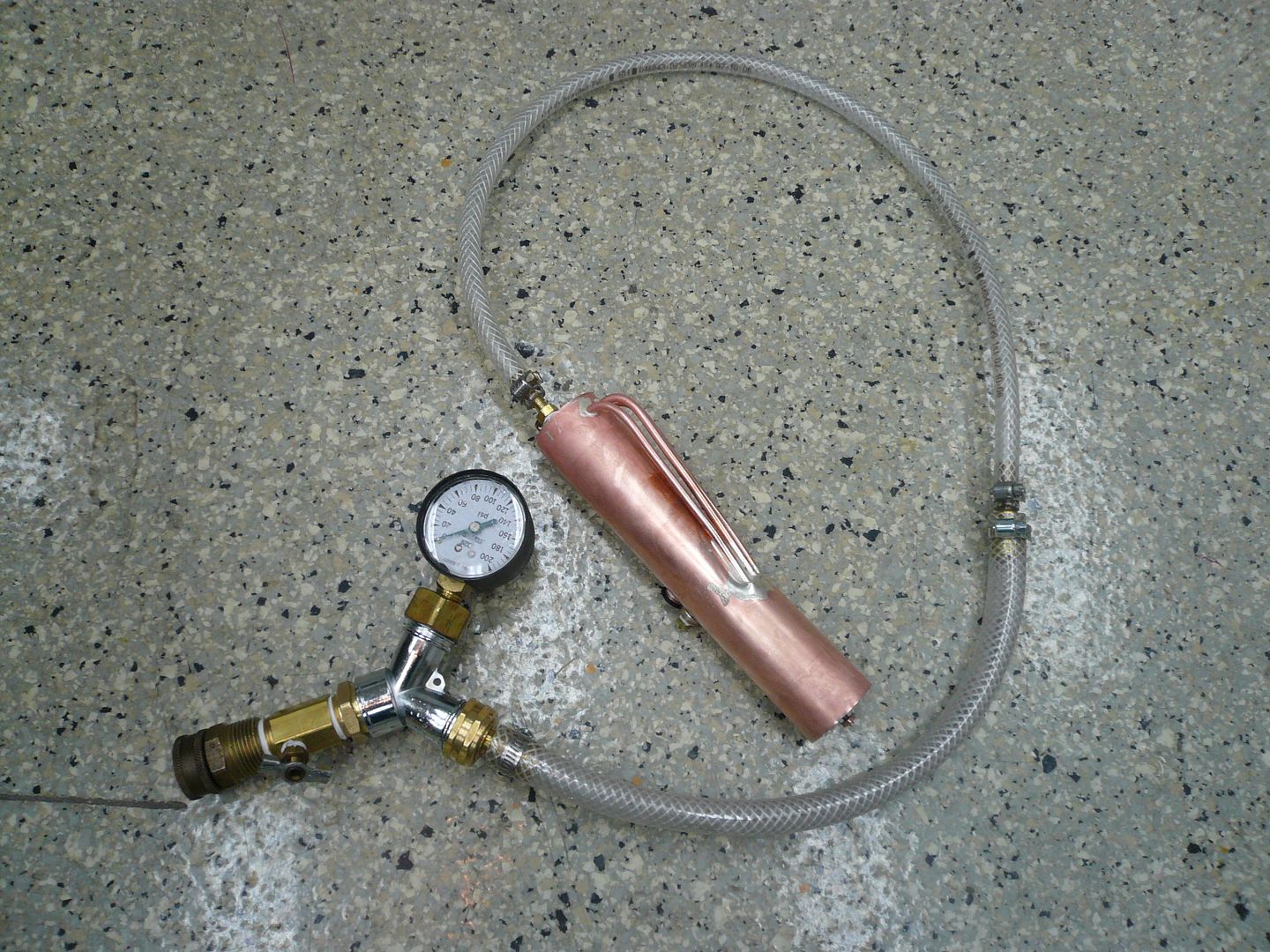
Pretty much everything came out of Home Depot. The end fitting connects to a garden hose. The petcock on the lower left is used as a manual pressure regulator. As its opened or closed, the pressure in the line drops and rises. The gauge is a common water pressure test gauge available at Home Depot. I was concerned about accuracy, so I compared this one to another I have, plus one I borrowed from my neighbor. All three read remarkably close. The clear tubing is braid reinforced PVC water line.
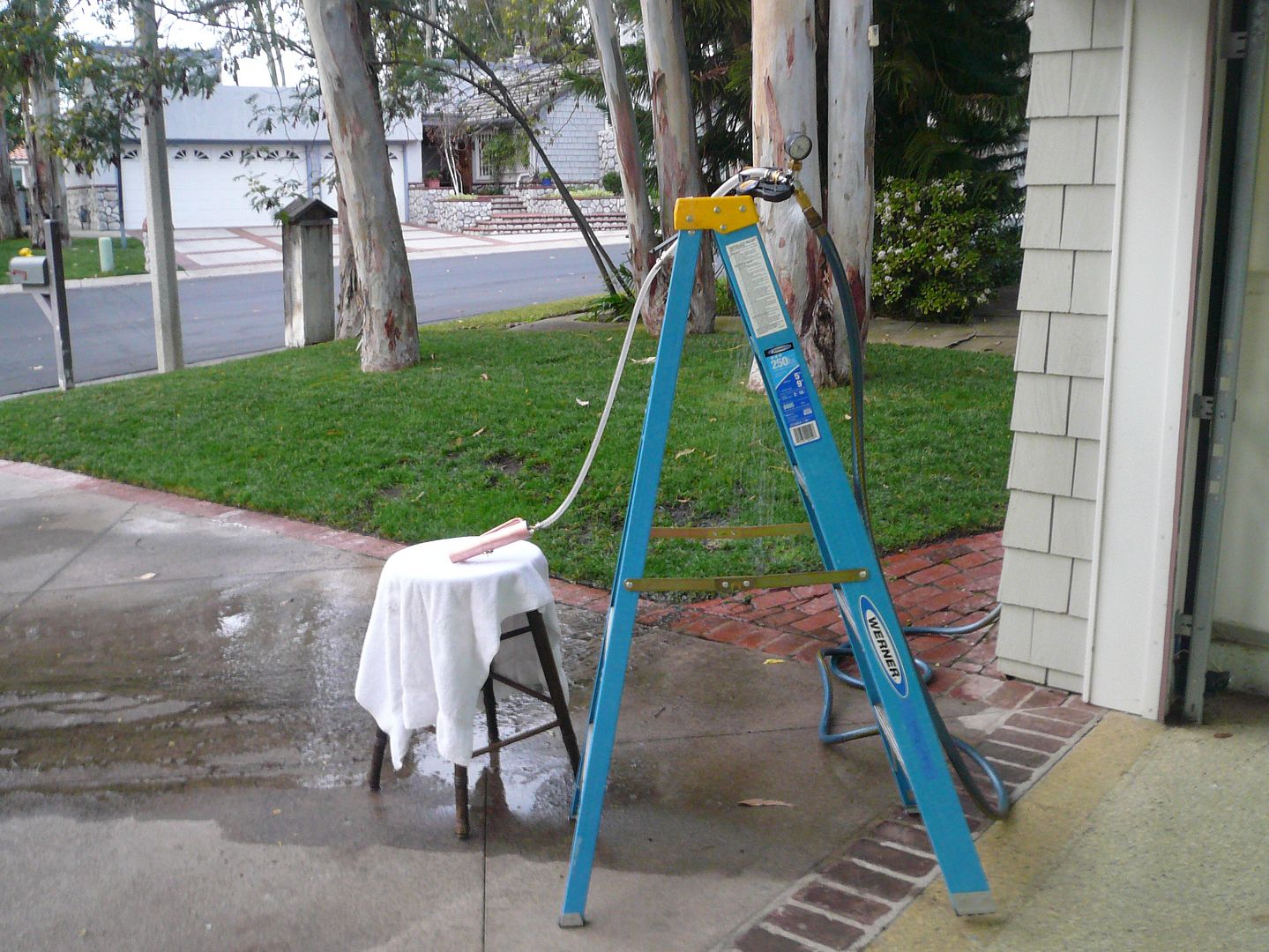
The boiler must be completely filled with water (no air) before starting the test. To do that, I clamped the gauge end to the top of a step ladder and let the boiler and tubing hang vertically. I then loosened one of the boiler end plugs and filled the boiler and tubing with water using a turkey baster. Once the boiler was full, I tightened the plug and continued filling the tube until there were no more air bubbles. With the clear PVC tubing, its pretty easy to see when all the air is out of the boiler and the line. With the petcock open, I attached my garden hose and turned on the water.
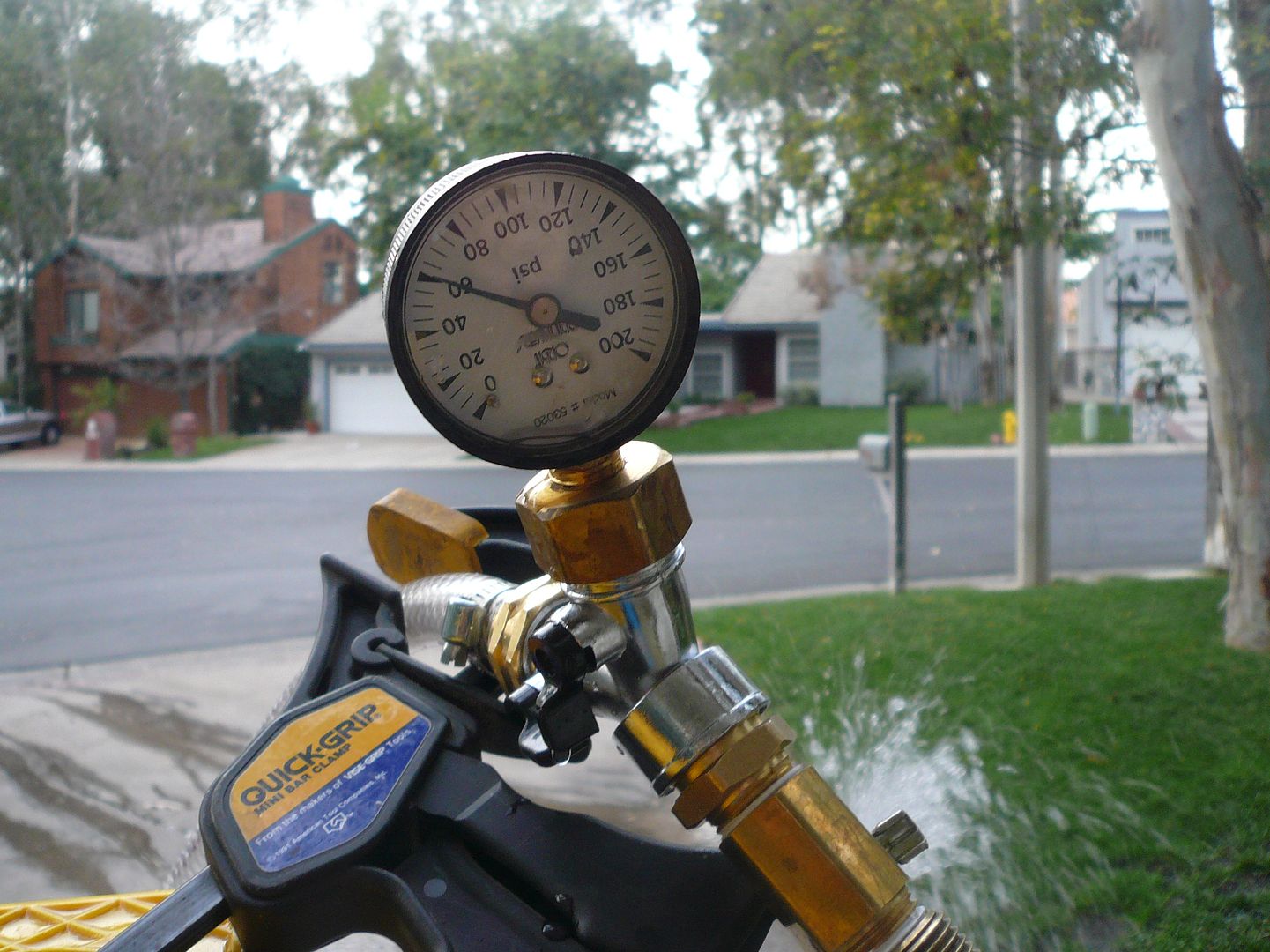
I left the petcock open to allow the last bit of air at the top of the tubing to bleed out, then slowly closed the petcock until the gauge read 60 psi.
The pressure was remarkably stable throughout the test. I thought Id have to keep fiddling with the petcock adjustment to hold at 60 psi but I didnt have to move it at all.
At about 20 minutes under pressure. I noticed a drop of water on the lower tube.
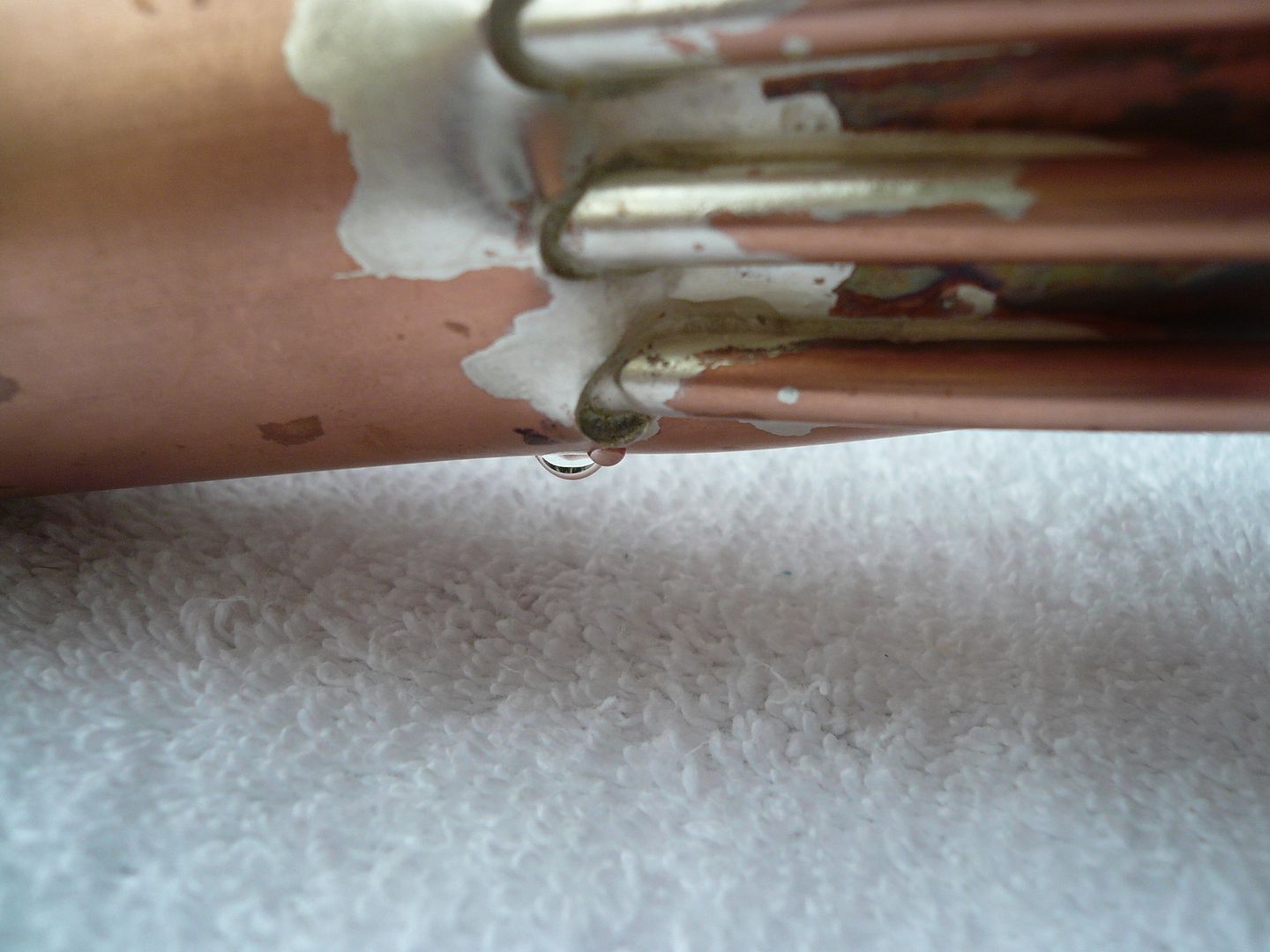
After making sure there were no other leaks, I stopped the test and re-soldered the joint. That required removing all the plugs, drying everything out, fluxing the joint and re-flowing the solder. It went very smoothly, but it was time consuming.
With the joint re-soldered, I started the test over. After 30 minutes at 60 psi there were no leaks. I released the pressure and re-ran the test for another 30 minutes. Again no leaks, so Im declaring the boiler good-to-go. Oh Happy Day!
Regards,
Dennis
Arnold, Dean, Doug & Ariz...Thanks for the comments.
Post #40
Boiler (Contd.)
With all the soldering complete, its time to pressure test the boiler.
The safety valve pops at 30 psi and, according to other builders, the tractor operates at 15-20 psi. Ill test to 60 psi or twice the pop-off pressure. The pressure will be brought up to 60 psi slowly and then held there for 30 minutes. Then the pressure will be released and the test will be repeated. If there are no leaks after the second run up, the boiler will be considered good.
Since Im not sure if Ill be doing more live steam projects, I didnt want to get involved in the time and expense of building a dedicated test pressure pump. Instead, Im going to use city water pressure to test my boiler. Water pressure at my house runs a pretty consistent mid-day pressure of 72-75 psi, so theres enough pressure for my test.
Heres my test rig:
Pretty much everything came out of Home Depot. The end fitting connects to a garden hose. The petcock on the lower left is used as a manual pressure regulator. As its opened or closed, the pressure in the line drops and rises. The gauge is a common water pressure test gauge available at Home Depot. I was concerned about accuracy, so I compared this one to another I have, plus one I borrowed from my neighbor. All three read remarkably close. The clear tubing is braid reinforced PVC water line.
The boiler must be completely filled with water (no air) before starting the test. To do that, I clamped the gauge end to the top of a step ladder and let the boiler and tubing hang vertically. I then loosened one of the boiler end plugs and filled the boiler and tubing with water using a turkey baster. Once the boiler was full, I tightened the plug and continued filling the tube until there were no more air bubbles. With the clear PVC tubing, its pretty easy to see when all the air is out of the boiler and the line. With the petcock open, I attached my garden hose and turned on the water.
I left the petcock open to allow the last bit of air at the top of the tubing to bleed out, then slowly closed the petcock until the gauge read 60 psi.
The pressure was remarkably stable throughout the test. I thought Id have to keep fiddling with the petcock adjustment to hold at 60 psi but I didnt have to move it at all.
At about 20 minutes under pressure. I noticed a drop of water on the lower tube.
After making sure there were no other leaks, I stopped the test and re-soldered the joint. That required removing all the plugs, drying everything out, fluxing the joint and re-flowing the solder. It went very smoothly, but it was time consuming.
With the joint re-soldered, I started the test over. After 30 minutes at 60 psi there were no leaks. I released the pressure and re-ran the test for another 30 minutes. Again no leaks, so Im declaring the boiler good-to-go. Oh Happy Day!
Regards,
Dennis
- Joined
- Jul 16, 2007
- Messages
- 2,987
- Reaction score
- 1,055
Hi Dennis, congratulations on the boiler build. For what it's worth you'll probably have a tough time getting more that 30 lbs. with a wick heat source. I built Rudy's tractor many years ago and the only time I could get over 30 was with a draft assist in the smoke stack. My 1" Case with a propane burner will make about 60-65 lbs. You won't need more than 20 lbs for the engine to run well anyway.
George
George
- Joined
- Feb 25, 2008
- Messages
- 464
- Reaction score
- 5
George...I thought I saw Rudy's tractor up in the corner when you did your shop video. I appreciate the operating information. As you know, the plans don't say anything about running the tractor.
Arnold, Bob, Dean...Thank you.
Post #41
Steam Dome
Now that the boiler is complete, I can install it and determine the exact location of the throttle stand and safety valve. Theyre enclosed by the steam dome. Its a pretty snug fit, so its important to know their exact location before making the steam dome.
Rudy made his steam dome in two pieces, but I want to add a few rivets, so Im going with a three part one: a dome, a cylindrical vertical section, and a mounting flange. Im also making mine slightly larger in diameter.
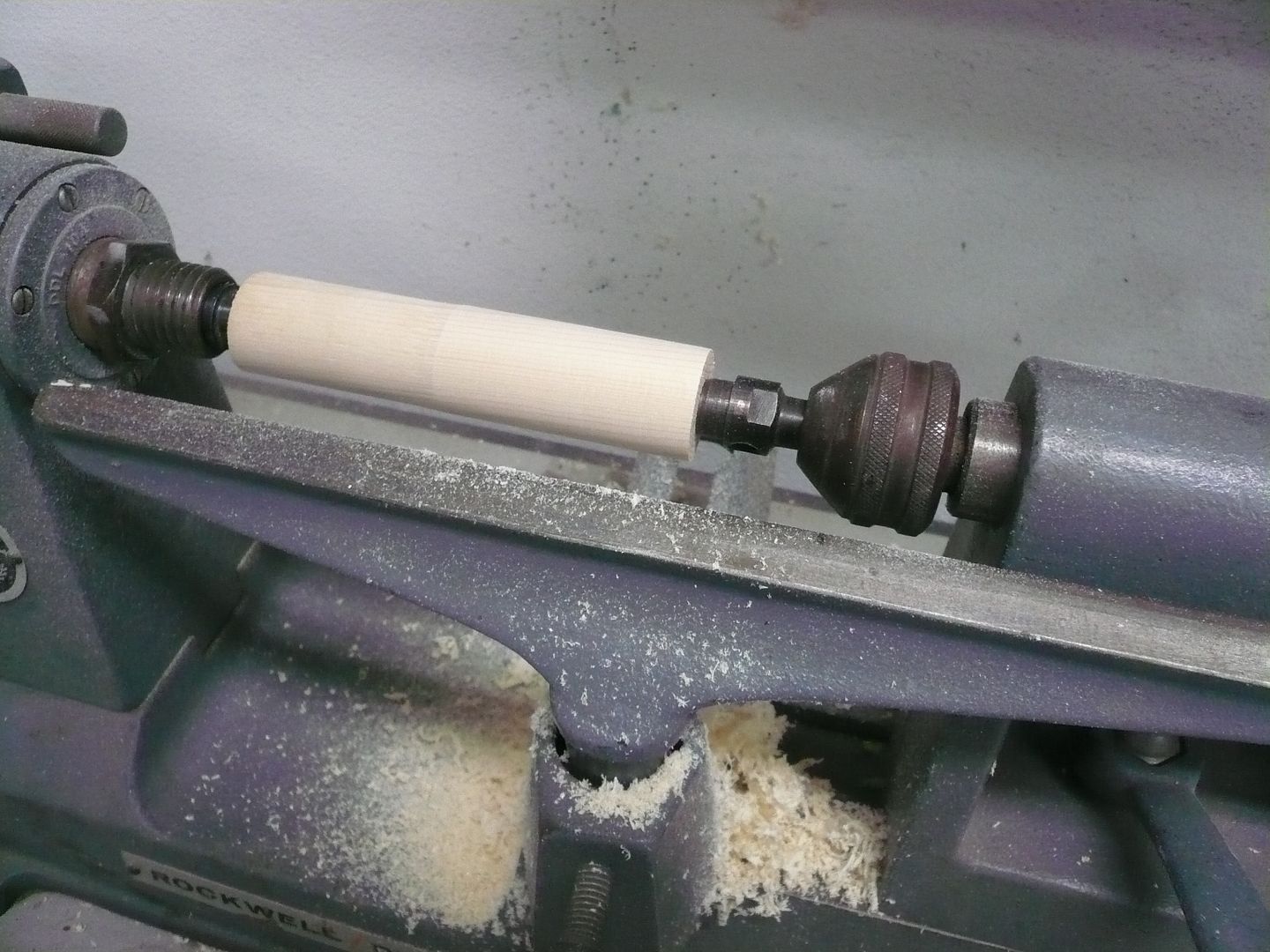
Im going to form the dome section by spinning it. For a one-off part like this, thats probably the least efficient way to do it, but its been several years since Ive done any spinning and this was a good excuse to give it another try.
Let me say right off, I am a rank amateur at this, so how I do it likely isnt the right way. Also, this wont be a tutorial because I dont have the ability to explain the spinning movements. You almost have to see it done. The quickest way to do that is go to YouTube and search for metal spinning. Its a lot of fun and something anyone can do if theyve got a lathe (either metal or wood). All the tools are homemade.
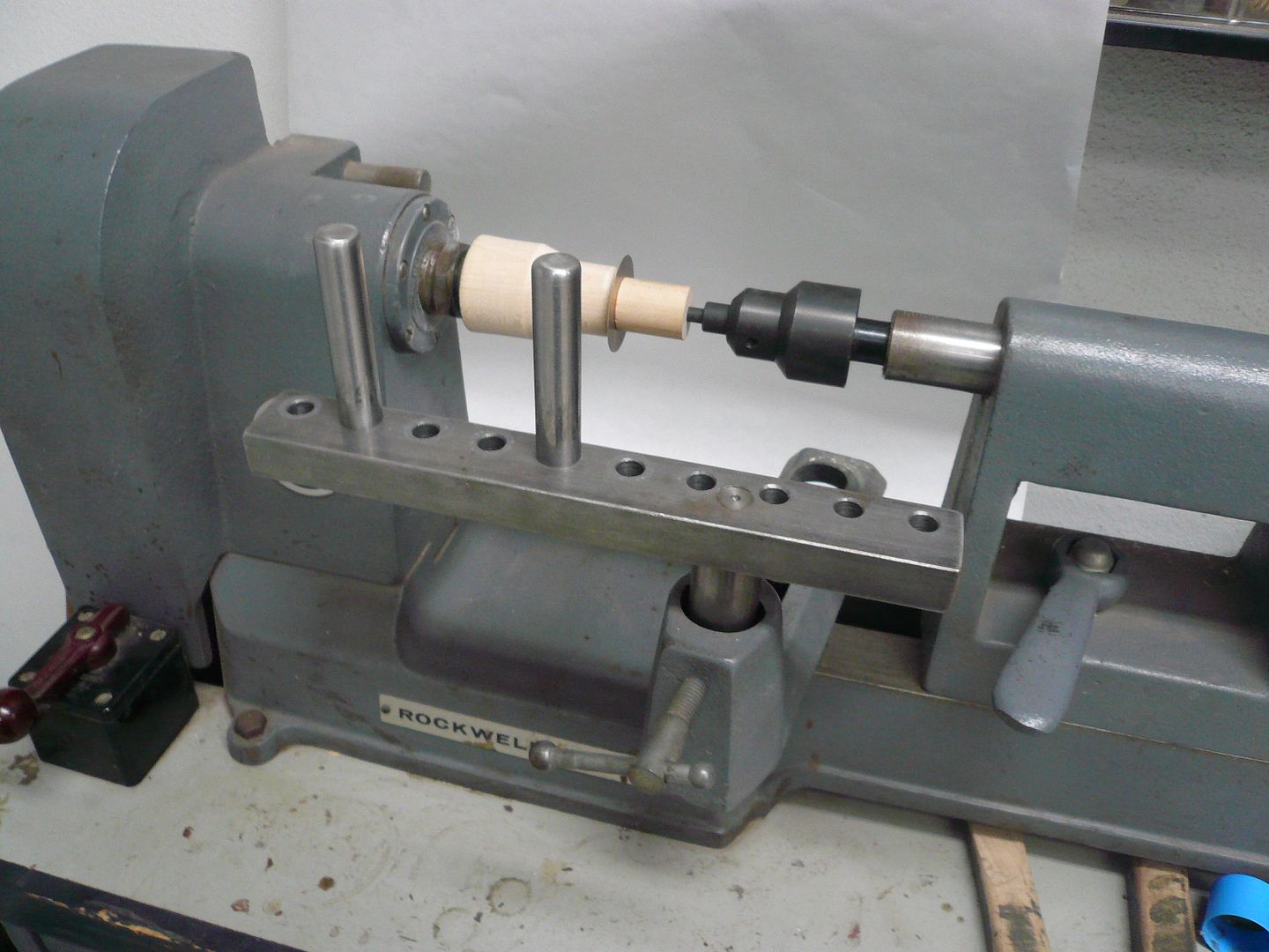
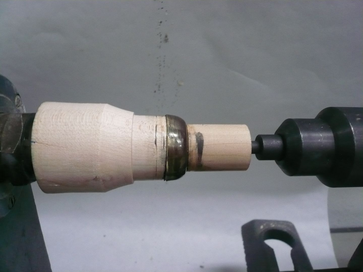
First step is to turn a form tool. I used maple, drilled, tapped and screwed directly to the headstock of my wood lathe. The follower block is also maple attached to a live center.
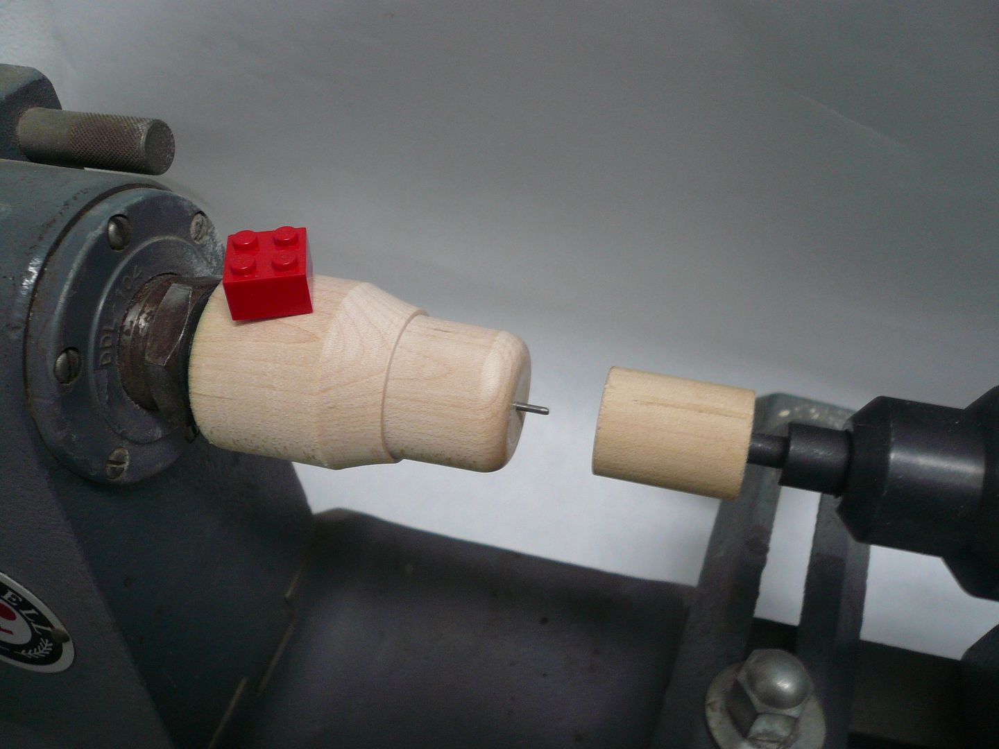
Fortunately, the dome has a dummy pressure gauge on the top, so theres a reason to put a hole in the center. You can spin without a center pin, relying on friction to hold the disc in place until its formed, but doing it that way involves a very high pucker factor.
Heres the set-up with a brass blank in place. I used 0.016 annealed brass.
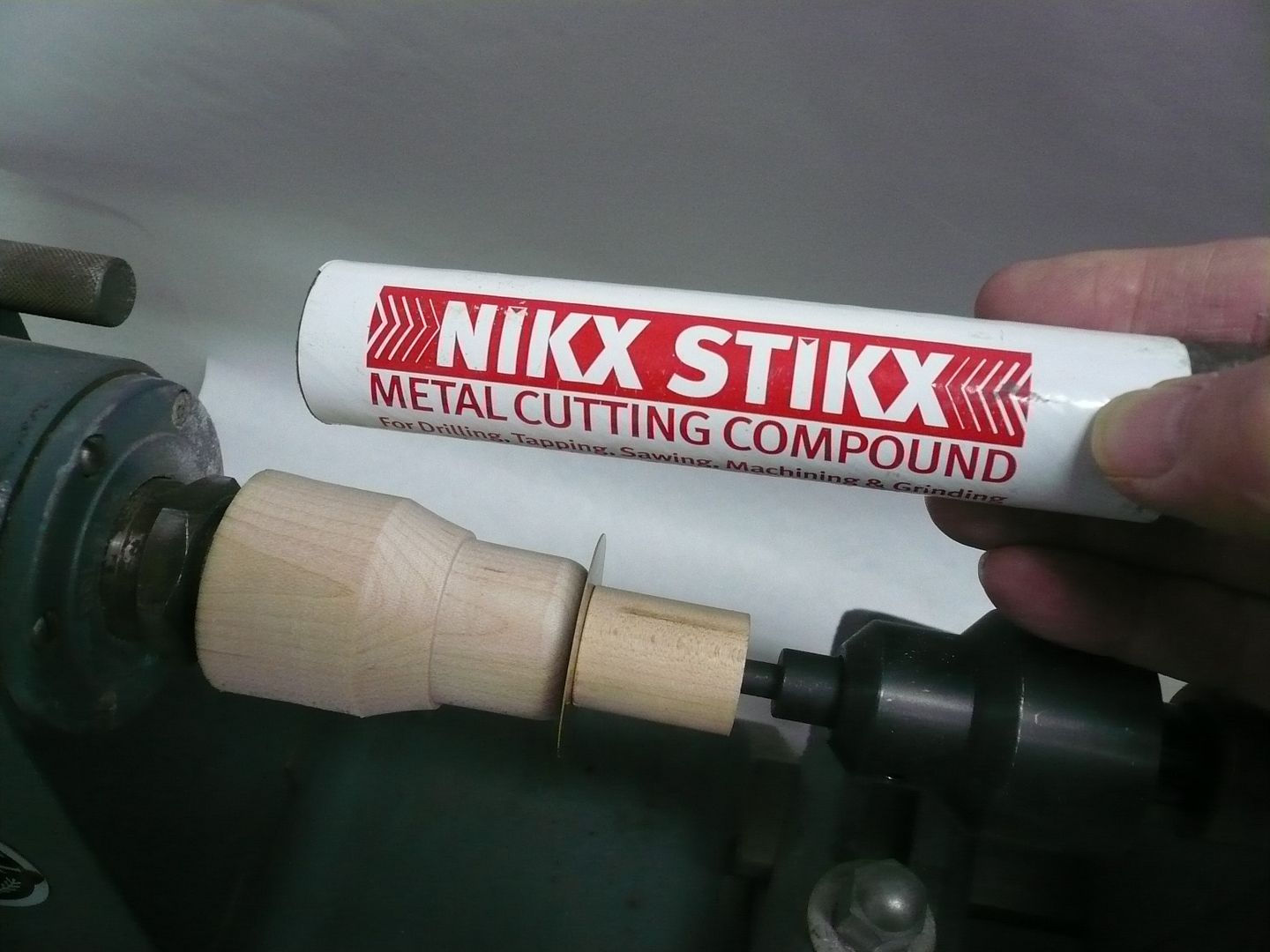
The disc needs to be lubricated. I use this waxy compound. Its cheap and works good. Ive also heard of using tallow, Ivory soap, oil, etc.
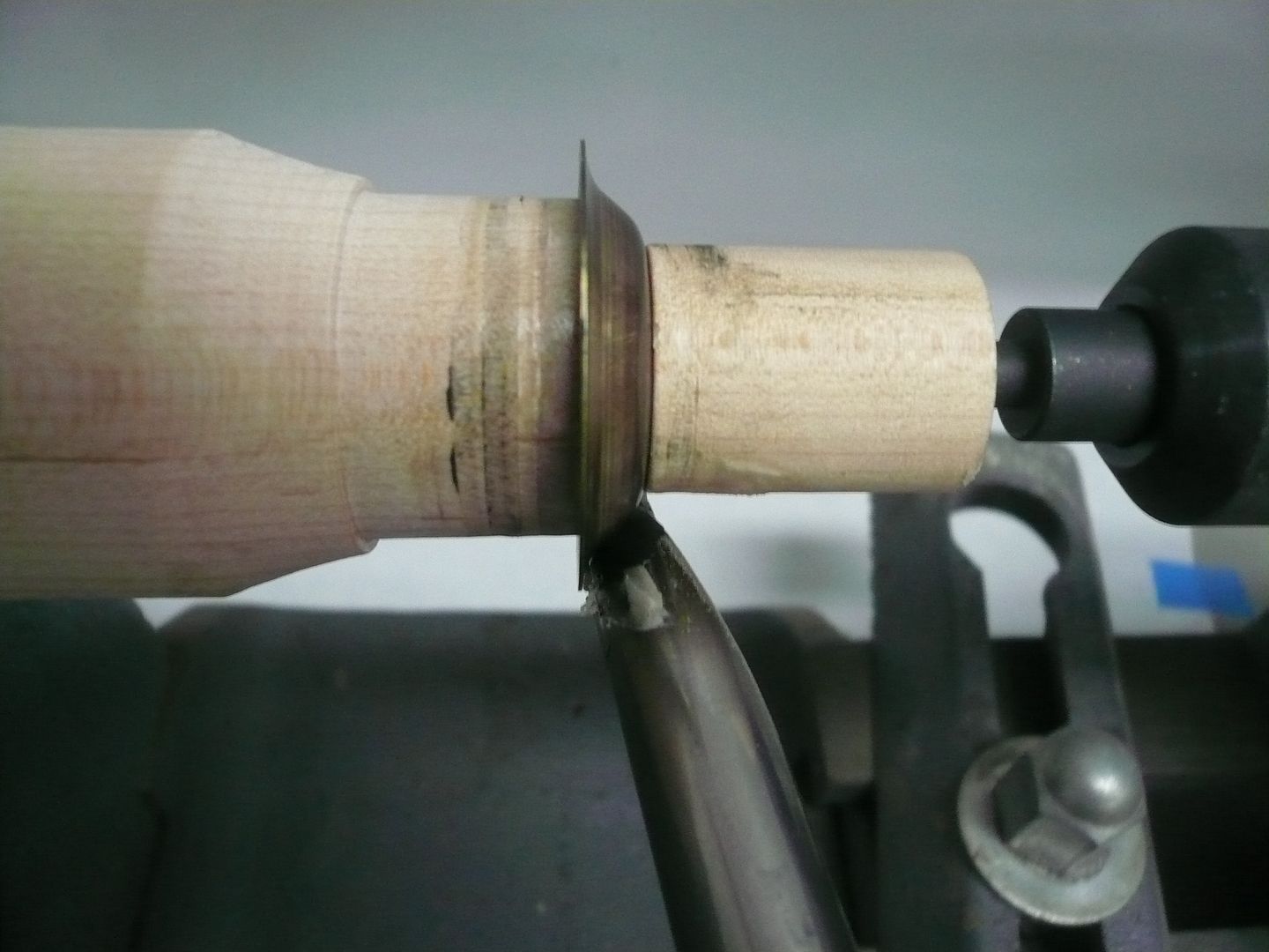
With the lathe running about 700-800 rpm, the tool is pressed against the bottom of the block and moved toward the headstock. Again, I dont have the ability to explain the tool movement you need to see it. YouTube has a lot of metal spinning videos that should help.
By the time Id formed it this far, the brass had work hardened and needed to be re-annealed.
After annealing I was able to lay the metal the rest of the way down (a skilled spinner would have been able to do this without the intermediate annealing).
Looking at the back wall, you can see you wouldnt want to wear your best white shirt for this.
Once you get in the groove of spinning its amazing how the metal moves, particularly on larger pieces.
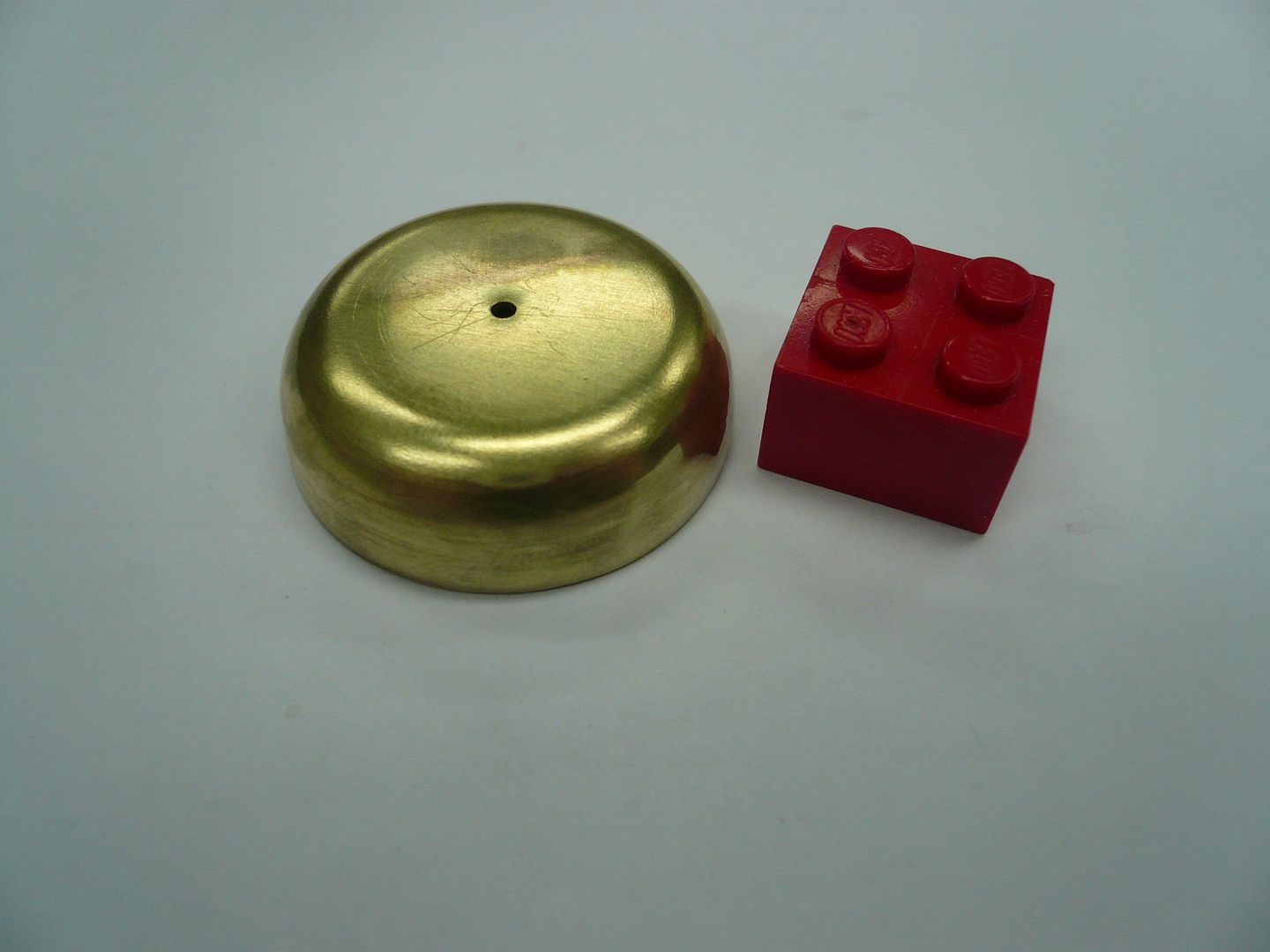
Most times the part is trimmed to final length on the tool just before laying down the last bit. I didnt because I wasnt sure how tall the finished part needed to be. Instead I trimmed it to final length later with a jewelers saw.
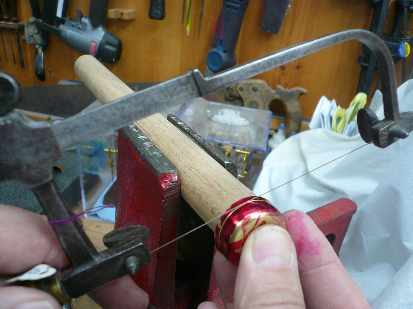
It seems to work best to saw all the way around the piece a time or two, gradually letting the saw break through.
The dome will slip inside the cylindrical upright which is the next part I'll build.
If you decide to give spinning a try, this video is worth renting. http://smartflix.com/store/video/480/Metal-Spinning-Workshop Its a two DVD set, the first tells you how to make your tools from drill rod and the second shows how to spin. Also, get some O temper aluminum to practice with. It spins beautifully without needing to stop for annealing.
Regards,
Dennis
Arnold, Bob, Dean...Thank you.
Post #41
Steam Dome
Now that the boiler is complete, I can install it and determine the exact location of the throttle stand and safety valve. Theyre enclosed by the steam dome. Its a pretty snug fit, so its important to know their exact location before making the steam dome.
Rudy made his steam dome in two pieces, but I want to add a few rivets, so Im going with a three part one: a dome, a cylindrical vertical section, and a mounting flange. Im also making mine slightly larger in diameter.
Im going to form the dome section by spinning it. For a one-off part like this, thats probably the least efficient way to do it, but its been several years since Ive done any spinning and this was a good excuse to give it another try.
Let me say right off, I am a rank amateur at this, so how I do it likely isnt the right way. Also, this wont be a tutorial because I dont have the ability to explain the spinning movements. You almost have to see it done. The quickest way to do that is go to YouTube and search for metal spinning. Its a lot of fun and something anyone can do if theyve got a lathe (either metal or wood). All the tools are homemade.
First step is to turn a form tool. I used maple, drilled, tapped and screwed directly to the headstock of my wood lathe. The follower block is also maple attached to a live center.
Fortunately, the dome has a dummy pressure gauge on the top, so theres a reason to put a hole in the center. You can spin without a center pin, relying on friction to hold the disc in place until its formed, but doing it that way involves a very high pucker factor.
Heres the set-up with a brass blank in place. I used 0.016 annealed brass.
The disc needs to be lubricated. I use this waxy compound. Its cheap and works good. Ive also heard of using tallow, Ivory soap, oil, etc.
With the lathe running about 700-800 rpm, the tool is pressed against the bottom of the block and moved toward the headstock. Again, I dont have the ability to explain the tool movement you need to see it. YouTube has a lot of metal spinning videos that should help.
By the time Id formed it this far, the brass had work hardened and needed to be re-annealed.
After annealing I was able to lay the metal the rest of the way down (a skilled spinner would have been able to do this without the intermediate annealing).
Looking at the back wall, you can see you wouldnt want to wear your best white shirt for this.
Once you get in the groove of spinning its amazing how the metal moves, particularly on larger pieces.
Most times the part is trimmed to final length on the tool just before laying down the last bit. I didnt because I wasnt sure how tall the finished part needed to be. Instead I trimmed it to final length later with a jewelers saw.
It seems to work best to saw all the way around the piece a time or two, gradually letting the saw break through.
The dome will slip inside the cylindrical upright which is the next part I'll build.
If you decide to give spinning a try, this video is worth renting. http://smartflix.com/store/video/480/Metal-Spinning-Workshop Its a two DVD set, the first tells you how to make your tools from drill rod and the second shows how to spin. Also, get some O temper aluminum to practice with. It spins beautifully without needing to stop for annealing.
Regards,
Dennis
rake60
Well-Known Member
- Joined
- Jul 8, 2007
- Messages
- 4,756
- Reaction score
- 124
Beautiful result from a metal spinning operation Dennis! :bow: :bow: :bow:
Metal spinning is a craft is dying off faster than the machining craft.
It's great to see a tutorial of it being applied to a hobby project.
Rick
Metal spinning is a craft is dying off faster than the machining craft.
It's great to see a tutorial of it being applied to a hobby project.
Rick
Wow, that dome looks really nice, Dennis. Beautiful, really.
I sure like that jewelers saw. Mine is modern, about 20 years old, and has none of the pleasing lines that yours exhibits.
Thanks for the show 'n tell on your spinning job. Something I've never done, and seldom seen.
Great post.
Dean
I sure like that jewelers saw. Mine is modern, about 20 years old, and has none of the pleasing lines that yours exhibits.
Thanks for the show 'n tell on your spinning job. Something I've never done, and seldom seen.
Great post.
Dean
zeeprogrammer
Well-Known Member
- Joined
- Mar 14, 2009
- Messages
- 3,362
- Reaction score
- 13
Excellent post Dennis.
I'd bet it caused a number of people to go off in search of learning more about spinning. I know I did.
I'd bet it caused a number of people to go off in search of learning more about spinning. I know I did.
- Joined
- Feb 25, 2008
- Messages
- 464
- Reaction score
- 5
Arnold,
Here's the set I made....
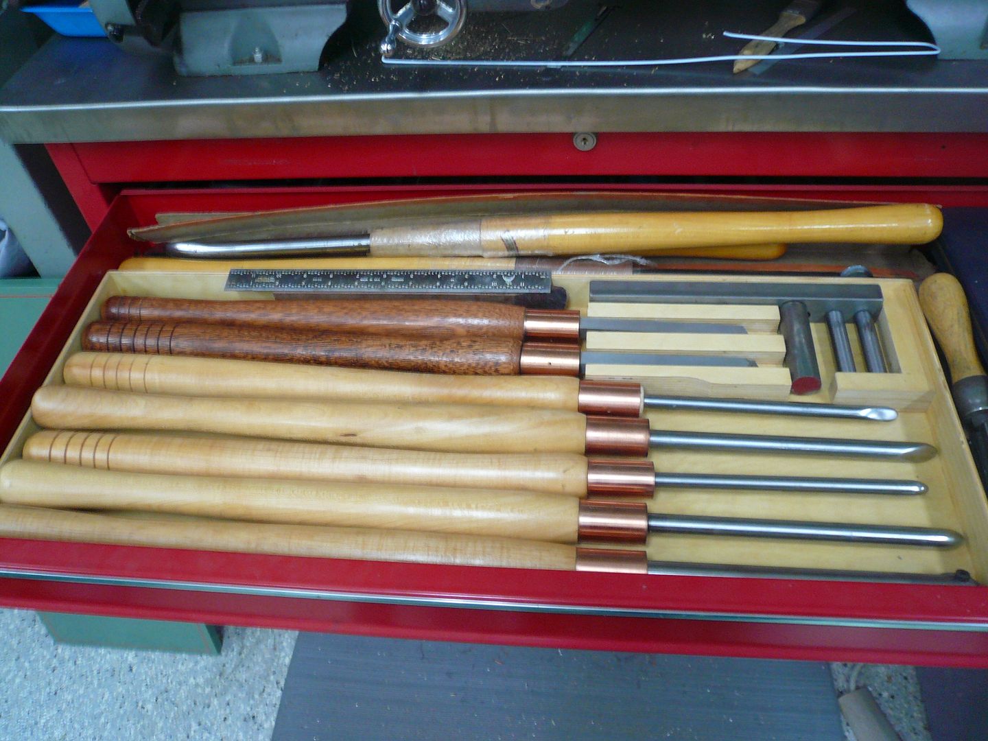
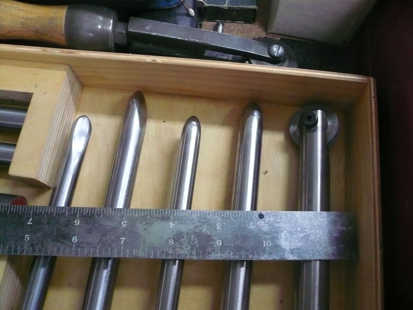
The tools are made from 1/2" and 5/8" drill rod and are about 28" long. The two in the back with the darker handles are trimming tools and are made from 1/2" square drill rod. From left to right the tools are: small combination, large combination, small round, large round and beading tool.
For trying spinning, you probably only need one of the small round nose tools. The rest can come later. I've seen a lot of tools made using a piece of shovel handle. The tools should be at least 28" long overall though because of the way you hold them. You also will need to make a steady rest with movable pins (see photo in my previous post).
I hope you'll try it...it's a lot of fun.
Dennis
Here's the set I made....
The tools are made from 1/2" and 5/8" drill rod and are about 28" long. The two in the back with the darker handles are trimming tools and are made from 1/2" square drill rod. From left to right the tools are: small combination, large combination, small round, large round and beading tool.
For trying spinning, you probably only need one of the small round nose tools. The rest can come later. I've seen a lot of tools made using a piece of shovel handle. The tools should be at least 28" long overall though because of the way you hold them. You also will need to make a steady rest with movable pins (see photo in my previous post).
I hope you'll try it...it's a lot of fun.
Dennis
Kind of off topic but,
I got a tour of the Pelco factory in Clovis CA. a couple of years ago. They are a US manufacturer of Security CCTV systems, and actually make 90% of their products in the U.S. The factory tour included the machine shop areas, the die cast areas, etc. One of the things that they demoed for us was a CNC metal spinning lathe. they use this to make the aluminum dome for exterior security cameras. Starting with a roughly 2' diameter circle of aluminum chucked between the formers the machine could spin a dome in about 45 seconds using several different tools.
Coolest thing I ever seen.
") - I appreciate the extra photos; as I'm sure some other people do.
- I appreciate the extra photos; as I'm sure some other people do.Harold Lee
Well-Known Member
- Joined
- Apr 23, 2008
- Messages
- 236
- Reaction score
- 2
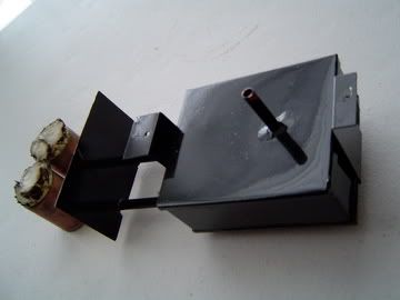
As I said in my last post, there are a lot of different ideas out there on type, packing and placement of wicking. I played with a few variations and thought Id share them.
...
Im interested in hearing other builders comments on how their burners worked.
Regards,
Dennis
Dennis,
Please forgive me for hijacking your wonderful post but you had asked about wicking used in the tractor burner. I used the Tiki Torch wick available from Lowes or Home Depot. I cut three pieces and put them in each burner tube.
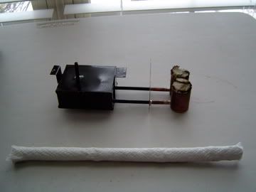
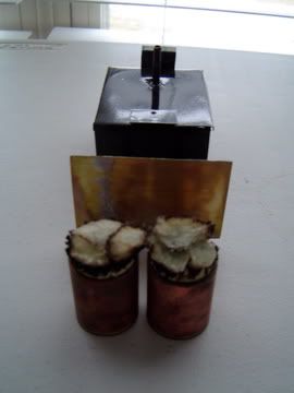
The one thing I added to his design was the heat baffle that I believe will help with containing the heat and prevent heating the rear of the tractor. All of this is conjecture of course but it does look good when viewing the tractor from the bottom.
Thank you again for sharing your work, I have been working on mine for over a year and have gotten many ideas and inspiration from you.
Harold
- Joined
- Feb 25, 2008
- Messages
- 464
- Reaction score
- 5
Rick, Dean, Zee/Carl, Arnold...Thanks for the comments.
Harold...I like your idea of the heat baffle and plan to incorporate it in my tractor. Thanks.
Post #42
Steam Dome (Contd.)
The dome needed to be complete in order to know what ID to make the vertical section (the dome slips inside the vertical section). The first step was to turn a mandrel to the OD of the dome.
I used wood, but aluminum might be better. The mandrel was wrapped with a piece of 0.016 brass long enough so there was a 1/4 overlap. The brass was then tied in place with binding wire.
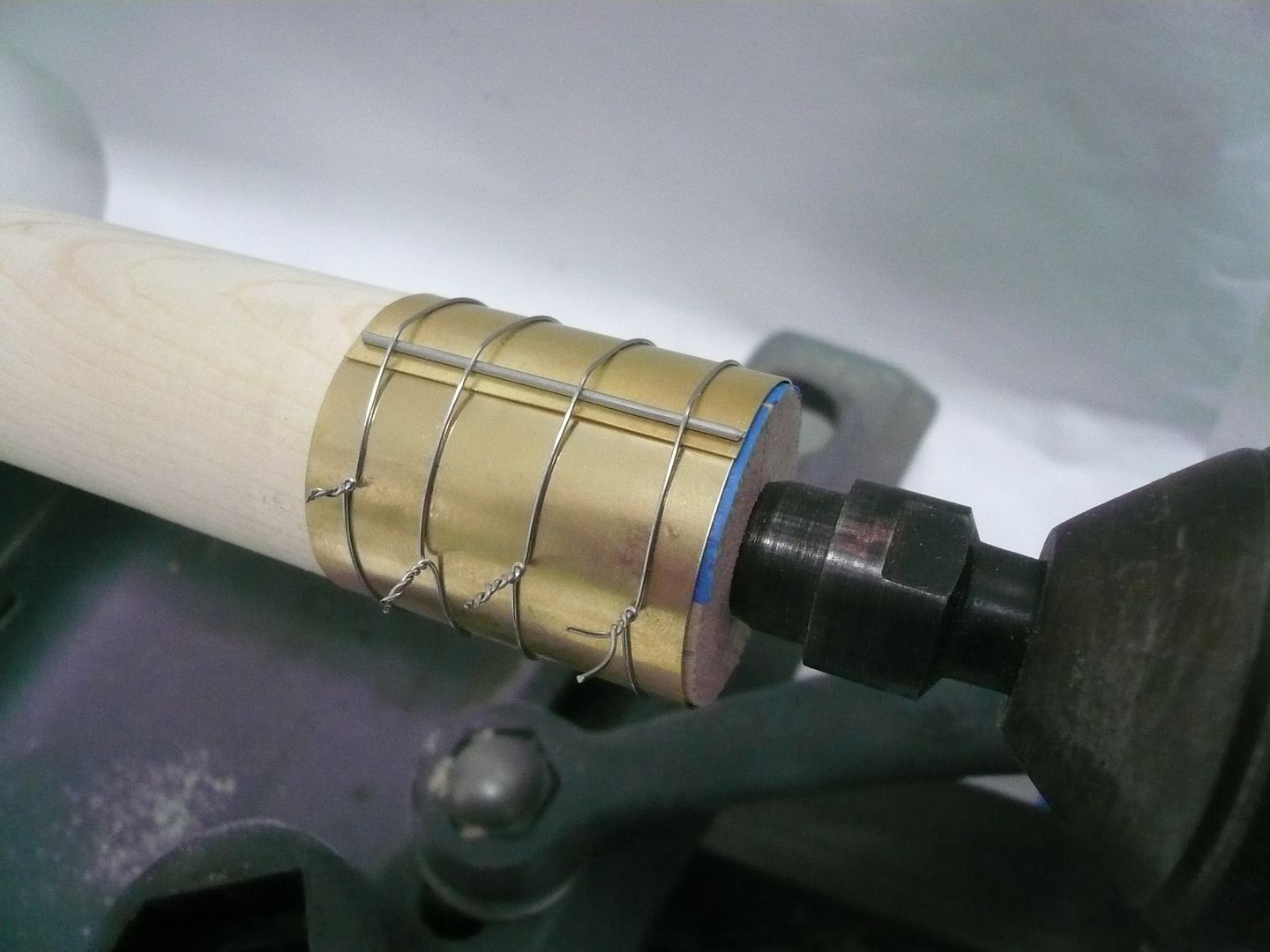
The piece of wire running parallel to the seam keeps the binding wires up and out of the solder joint. You cant see it, but before wrapping the brass, I coated the overlap area with paste solder. With everything tied snugly, I heated the seam with a small butane torch to complete the joint. The solder is just to hold things together until rivets are in place.
Before taking the part off the lathe, I used the lathe index to mark four 90 degree reference lines for later use.
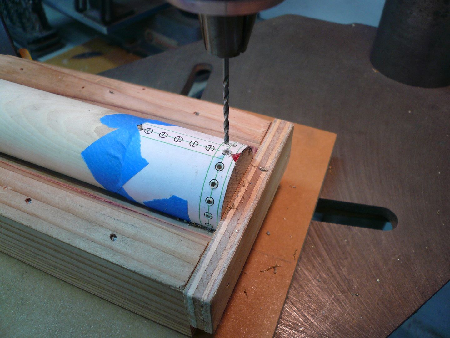
Ill have a horizontal row of rivets around the top of the dome and a vertical row along the seam. I used a paper pattern rubber cemented to the part to locate the rivet holes for drilling.
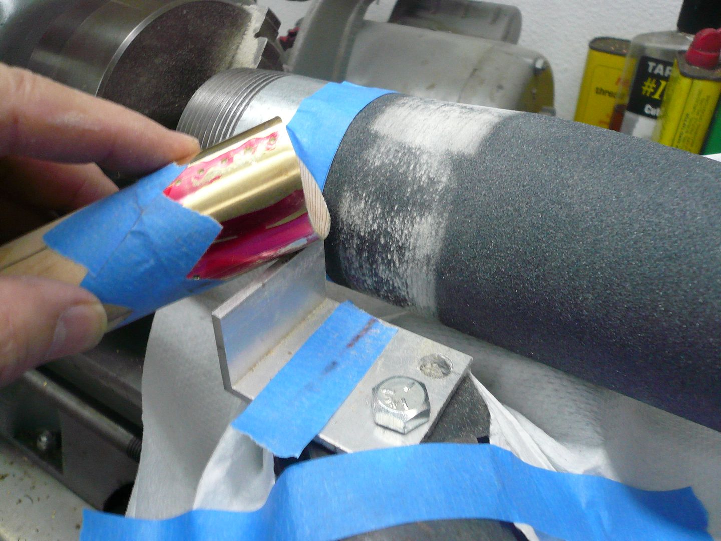
After the holes were drilled, the part was reversed on the mandrel so the base could be contoured. The contour is formed by wrapping a piece of pipe (same diameter as the boiler casing) with emery paper. For contouring, I used a fixture to hold the center line of the dome perpendicular to the center line of the lathe. The fixture is nothing but a piece of properly sized angle bolted to the cross slide.
Once I was happy with the contour, I installed the rivets (forgot to take a picture)
and moved on to the mounting flange.
Rudy used a narrow mounting flange soldered to the base of the vertical. I wanted to put a ring of rivets around mine like the real tractor, so I made mine wider. Also, I wanted to be able to remove the dome without having to unscrew two 2-56 screws located at the bottom of a tall tube so I used a ring of vertical fingers to hold the upright.
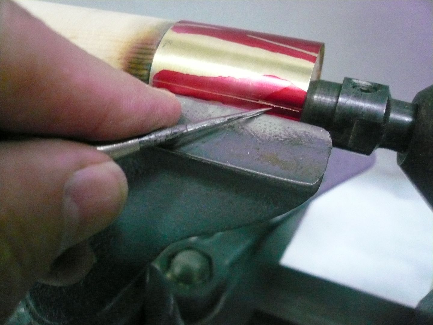
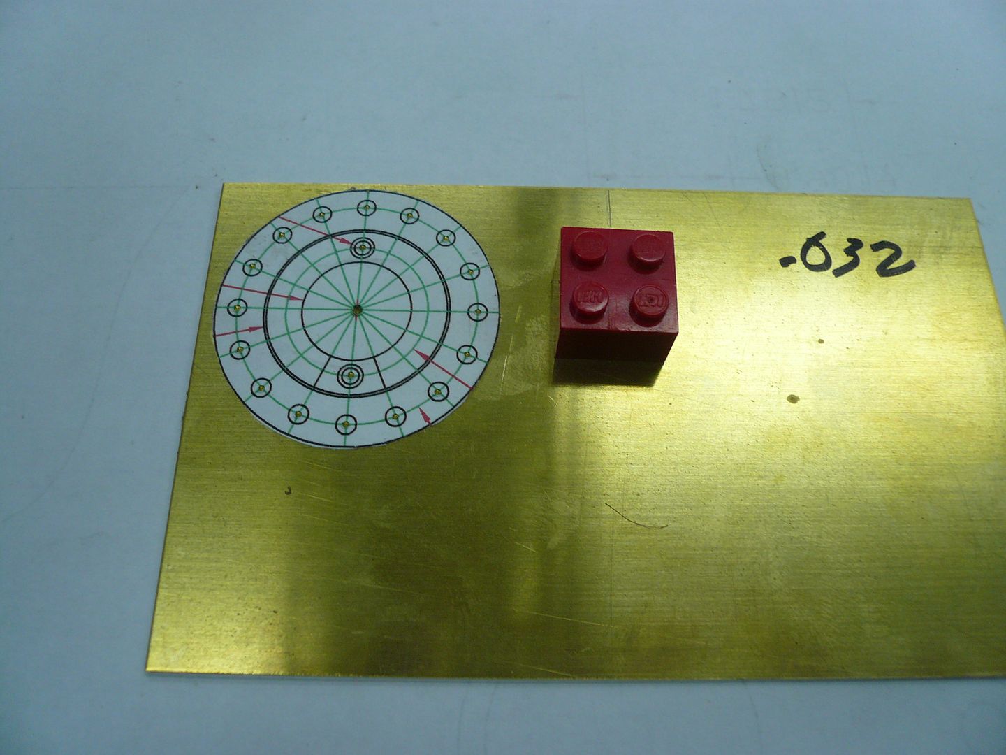
The flange starts with a piece of 0.032 brass and a paper pattern.
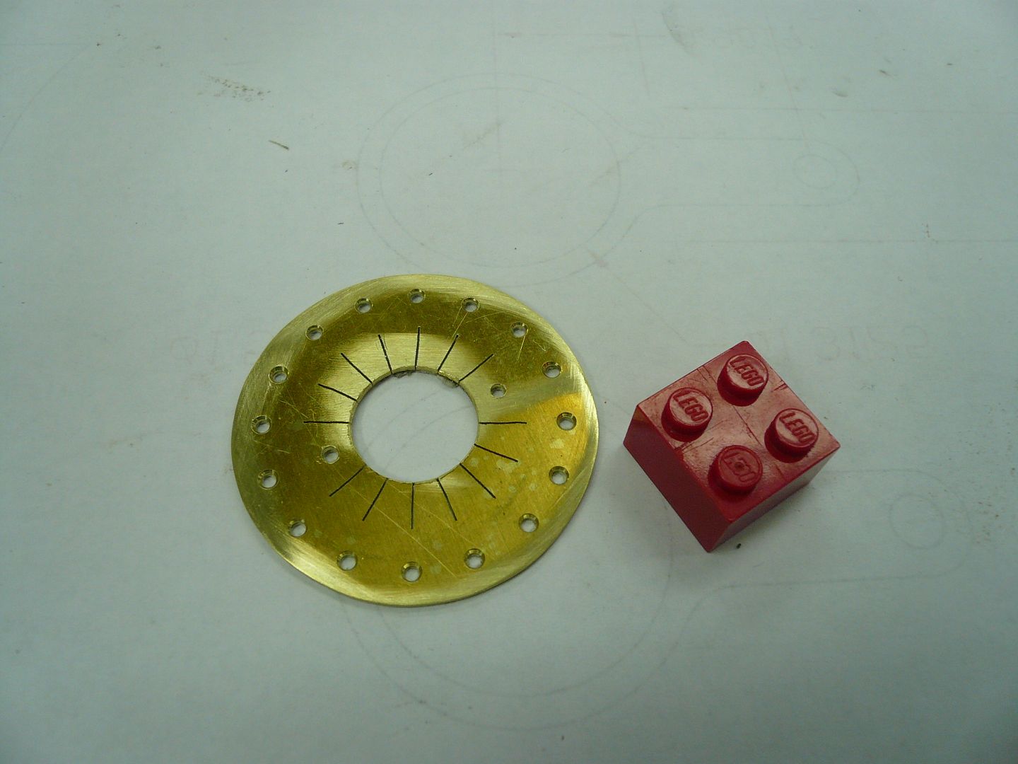
All the holes and shaping are done in the flat. I cut the radial slots for the fingers with a jewelers saw.
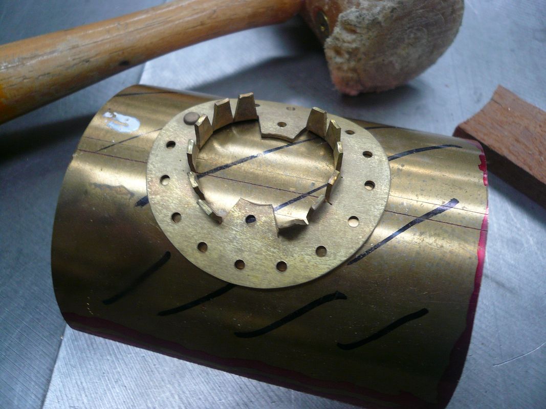
The fingers were then bent and the flange was formed over a piece of scrap boiler casing. I annealed the part before bending and forming.
The next operation was installation of rivets.
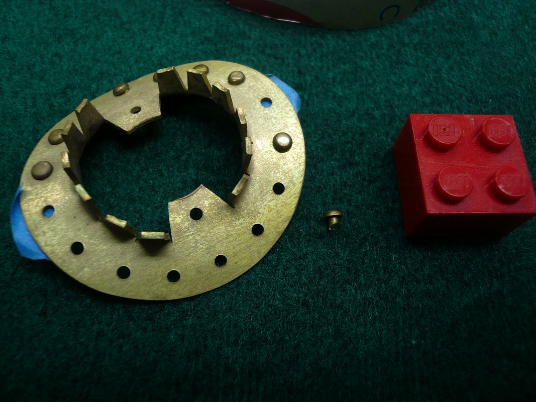
The rivets need to be flush on the bottom so the holes need to be slightly countersunk. If the rivets aren't flush, the flange won't lay flat against the boiler casing.
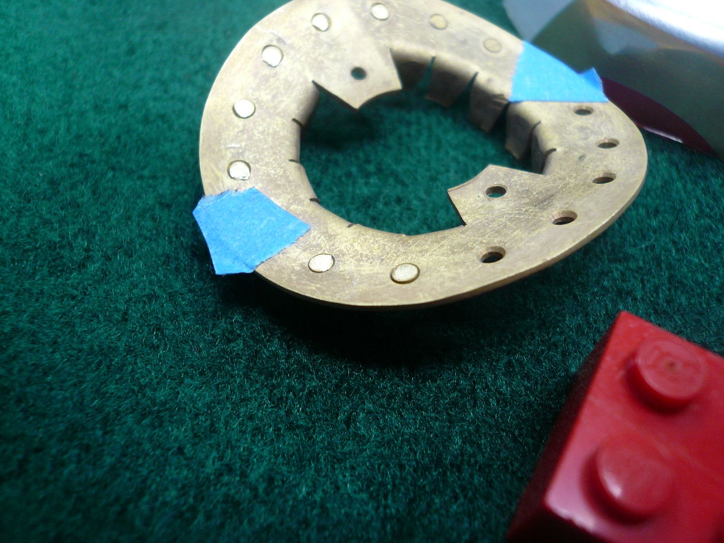
The two pieces of tape are to remind me not to put rivets in those two holes. Theyre my reference points for locating the flange when drilling the mounting holes in the boiler casing.
I had a terrible time getting the short rivets in the holes, even with a tweezers , until I hit upon using double sided tape to hold them.
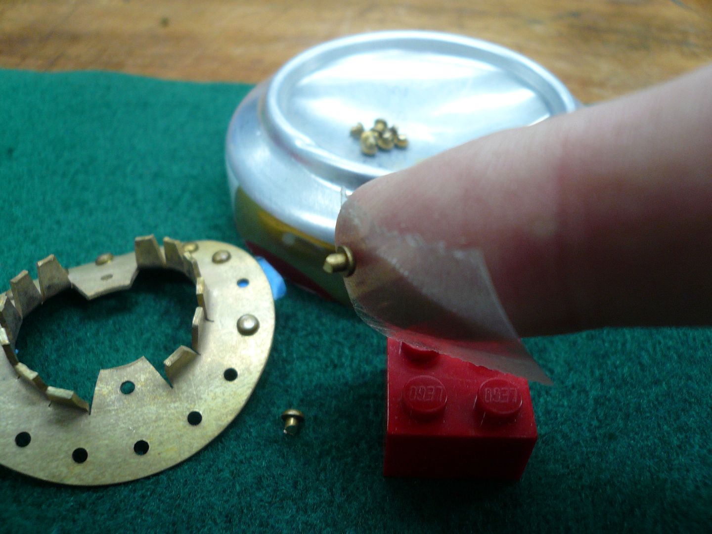
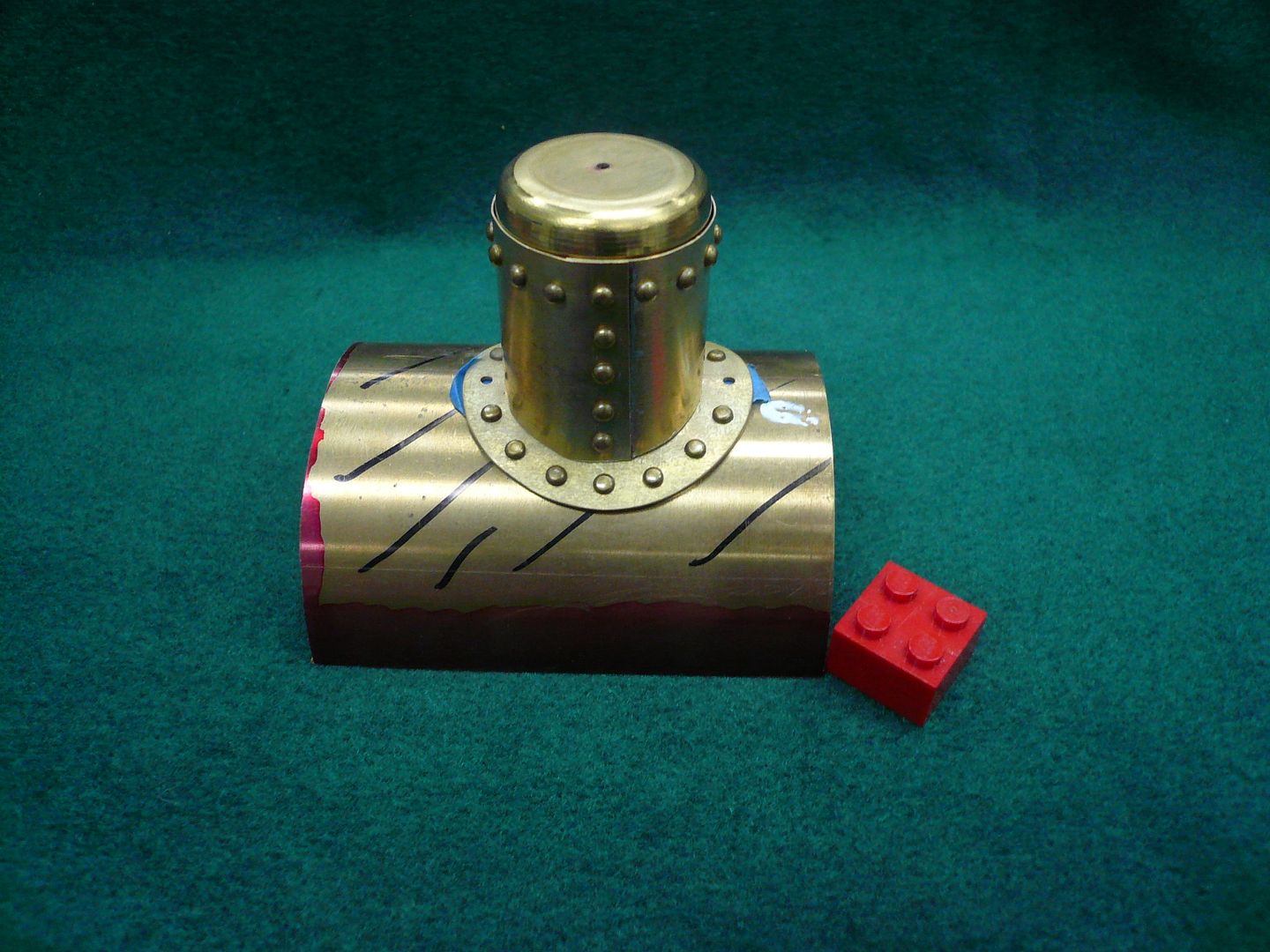
Heres what the finished steam dome looks like less the slot for the throttle control.
Regards,
Dennis
Harold...I like your idea of the heat baffle and plan to incorporate it in my tractor. Thanks.
Post #42
Steam Dome (Contd.)
The dome needed to be complete in order to know what ID to make the vertical section (the dome slips inside the vertical section). The first step was to turn a mandrel to the OD of the dome.
I used wood, but aluminum might be better. The mandrel was wrapped with a piece of 0.016 brass long enough so there was a 1/4 overlap. The brass was then tied in place with binding wire.
The piece of wire running parallel to the seam keeps the binding wires up and out of the solder joint. You cant see it, but before wrapping the brass, I coated the overlap area with paste solder. With everything tied snugly, I heated the seam with a small butane torch to complete the joint. The solder is just to hold things together until rivets are in place.
Before taking the part off the lathe, I used the lathe index to mark four 90 degree reference lines for later use.
Ill have a horizontal row of rivets around the top of the dome and a vertical row along the seam. I used a paper pattern rubber cemented to the part to locate the rivet holes for drilling.
After the holes were drilled, the part was reversed on the mandrel so the base could be contoured. The contour is formed by wrapping a piece of pipe (same diameter as the boiler casing) with emery paper. For contouring, I used a fixture to hold the center line of the dome perpendicular to the center line of the lathe. The fixture is nothing but a piece of properly sized angle bolted to the cross slide.
Once I was happy with the contour, I installed the rivets (forgot to take a picture)
and moved on to the mounting flange.
Rudy used a narrow mounting flange soldered to the base of the vertical. I wanted to put a ring of rivets around mine like the real tractor, so I made mine wider. Also, I wanted to be able to remove the dome without having to unscrew two 2-56 screws located at the bottom of a tall tube so I used a ring of vertical fingers to hold the upright.
The flange starts with a piece of 0.032 brass and a paper pattern.
All the holes and shaping are done in the flat. I cut the radial slots for the fingers with a jewelers saw.
The fingers were then bent and the flange was formed over a piece of scrap boiler casing. I annealed the part before bending and forming.
The next operation was installation of rivets.
The rivets need to be flush on the bottom so the holes need to be slightly countersunk. If the rivets aren't flush, the flange won't lay flat against the boiler casing.
The two pieces of tape are to remind me not to put rivets in those two holes. Theyre my reference points for locating the flange when drilling the mounting holes in the boiler casing.
I had a terrible time getting the short rivets in the holes, even with a tweezers , until I hit upon using double sided tape to hold them.
Heres what the finished steam dome looks like less the slot for the throttle control.
Regards,
Dennis
Similar threads
- Replies
- 111
- Views
- 21K