- Joined
- Dec 2, 2008
- Messages
- 971
- Reaction score
- 8
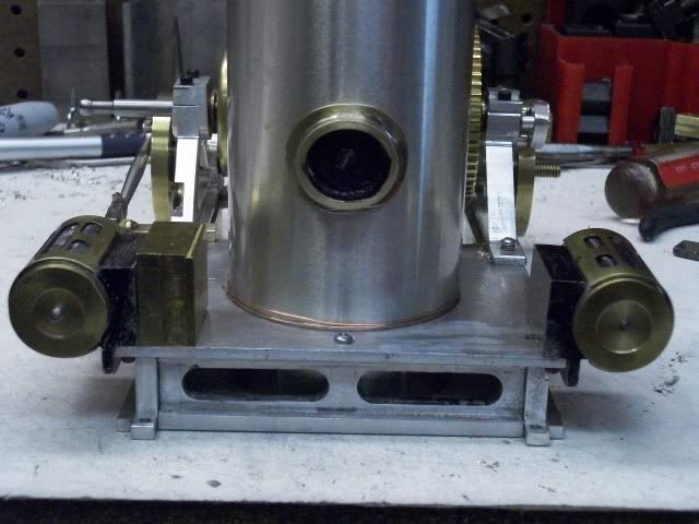
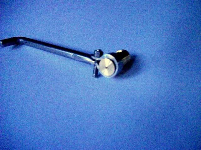
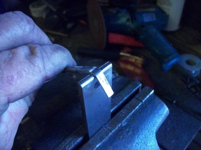
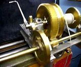
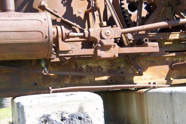
Just when I thought I knew How this winch worked, I found out something new. Here is a picture of the part where the rotation of the clutch lever applies axial thrust to a pin in the end of the shaft. I have looked at this picture for years and got it wrong. It appears that the part marked here:
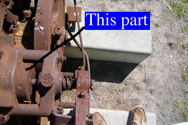
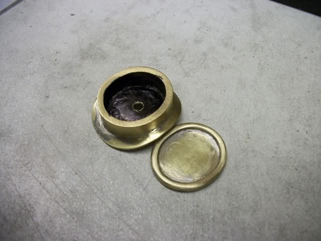
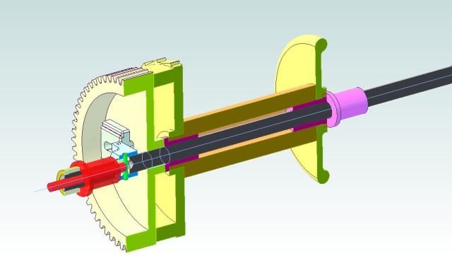
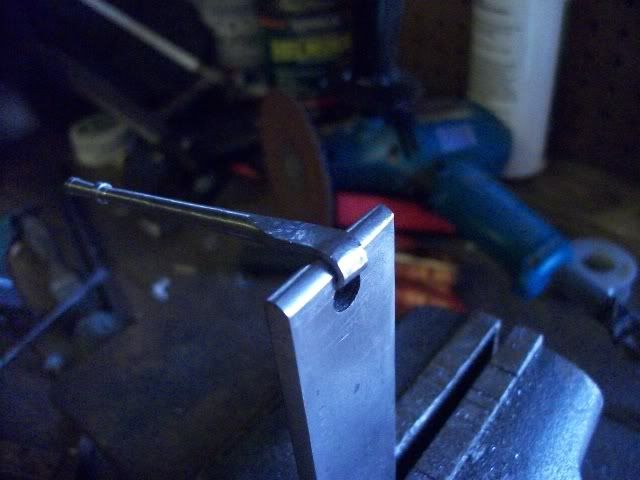
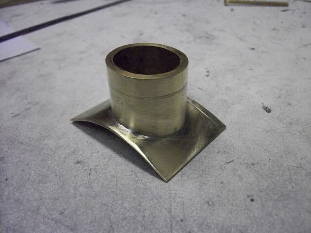
Is part of the bearing support stand and that the shaft rotates inside of it. I was wrong. In the next view from a different angle and under different light, it is clear that it is not part of the bearing stand, you can see the fine line of separation.
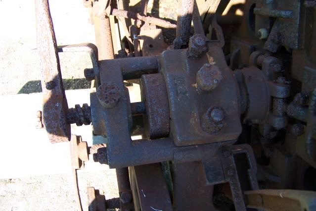
It is fixed to the shaft and rotates against the bearing stand or against a bushing. This is critical. When the clutch pin is pushed in, it pushes the clutch shoes out against the clutch drum but some of that force is transferred to the gear face by the sliders, and the shaft wants to move in that direction as well. I knew that there had to be a thrust collar somewhere but I could not see it. So I had done it wrong. I had used flanged oillite bushings at both ends of the drum. They let the drum turn on the shaft, and they transferred the axial thrust to a flanged bushing in the stand at the far end of the drum. It worked, as I have demonstrated, but it was fiddly and difficult to adjust. It also added a lot of friction to the whole thing. It added enough drag that I felt the need to do some testing to be sure that the engine will have enough power to drive the winch at 200/300 RPM.
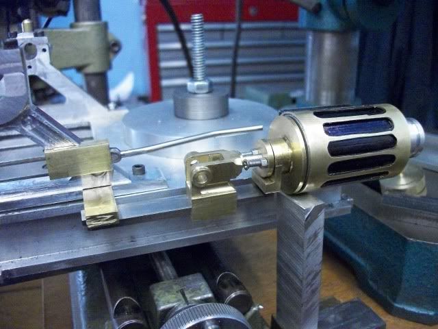
I had previously used my Unimat in a to drive the winch in trials, so yesterday, I rigged up a more solid test stand with the unimat drive.
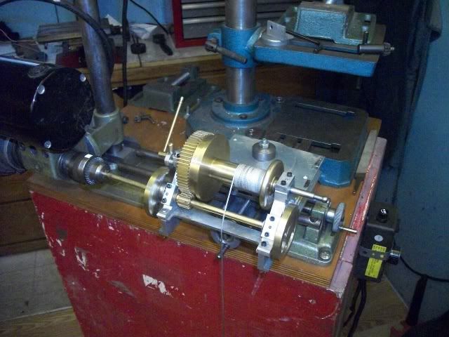
Lowest speed with belt drive.
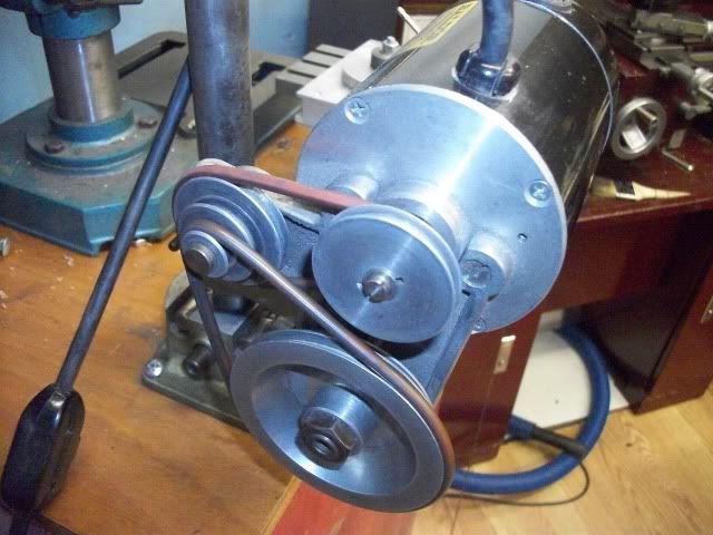
And reduced to about 200 RPM with a router control box. This box does not give good torque at very low speeds. It is easy to stall the chuck between your fingers. Not very precise but it seems to be in the power range of a twin cylinder air engine.
It took a little bit of fiddling to get the spindle and the crankshaft aligned and a little bit more time to get the clutch adjusted sot that it would engage and disengage smoothly. Playing with this thing is so much fun that I spent some time just playing. I noticed that when the clutch was applied, there was some flexing in the base and that the bearing stands flexed outwards as a result of the thrust being transferred through the winch drum. I was able to lift and lower a 5 pound weight with moderate pressure on the clutch lever but the Unimat motor wasn't happy. It would slow from 200 RPM to less that 100 RPM and get real jerky and stall.
I also noticed an irritating noise from the gears. They have never been run together for more than a few minutes and they had been in a box under the bench for over a year so they weren't bright and shiny. I didn't like the noise and I didn't like the flex so I took it completely apart and put just the pinion shaft and the winch shaft with gear back on the frame. I thought I would let the gears run in with a touch of Brasso and 30weight oil while I scoped out the clutch works.
In just a few minutes, the gears were running very smoothly so I let them run a few minutes more while applying some load with my finger on the big gear. I took them out of the frame and washed them with solvent and reassembled the whole thing for some more observation (playing). Gear noise all gone, smooth as silk. Flex and friction drag still there. I was starting to think that I needed ball bearing thrust washers at each end of the drum but that would be a real lubrication problem.
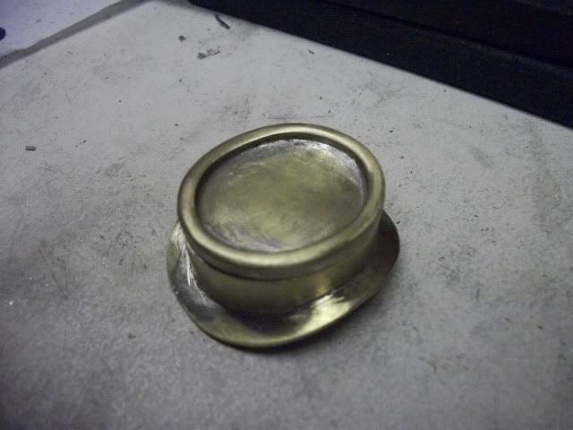
The quitting whistle blew so I cleaned up and headed to the house feeling a little a let down. After dinner, I was going through my "donkey" files, pictures and drawings, getting better organized to resume this project when I finally noticed the small separation line in the second photo above. Ureeka! That is the answer. That IS a thrust collar. All the axial thrust is absorbed right there. No transfer to the winch drum or to the bearing stand at the far end. I will still leave the flanged bushings at both ends of the drum to keep it in position but the contact between the flange bushing faces will be completely unloaded, even under maximum clutch pressure.
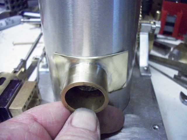
This morning, I turned up a brass thrust collar soldered it to the end of the shaft. I had to adjust some lengths and clearances but I got it all back together. WOW! What a difference. No flex, and without the flex, the additional friction caused by bearing misalignment as the stands flexed out of parallel was gone. The electric motor slowed only slightly as the clutch was applied, even when I increased the weight to 3 pounds. It worked so well that I played with it for another hour, up, down, float, feather, hold, faster, slower, heavier, lighter and I got the feel of the machine and I was not satisfied with the action.
There is no over-center or knuckle-in action. When the lever is at the full end of travel, the clutch linkage comes almost straight but due to the geometry, it will not knuckle in. It has to be held. If you release pressure, it doesn't immediately drop the load, but it begins to slip and soon disengages completely. There is no quadrant or notches to hold the lever either. On the real one there is a stop at the disengaged end of travel but there is nothing at the full on end of travel.
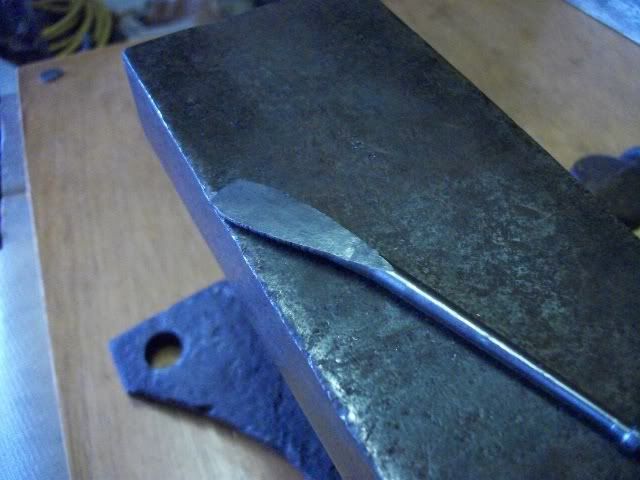
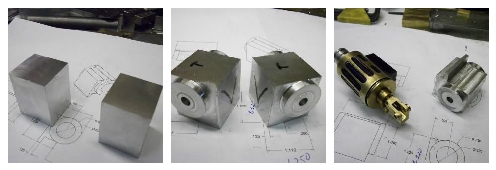
So I start thinking. I redesigned this part of the machine because I don't think that I can cut internal square threads at this scale (or any other scale). I used a slot, milled at an angle across the actuator instead of a full screw thread, creating a straight ramp instead of a helix. I could file of the end of the slot so there is a straight step at the top of the ramp. So I did.
Now when the pin that acts as the internal thread reaches that flat spot at the top of the ramp, it notches in and will stay there until the lever is pulled back. The action is smooth and positive and subtle. No hint of any binding. I did have to readjust the clutch because of the shortening of the inclined part of the ramp. The adjustment is a real pain because it involves taking the drum out of the stands and making small adjustments to the position of the gear on the shaft. I bet they had a better way.
Of course they did. Thats is what the threaded hickey is sticking out of the end of the actuator, a clutch adjuster!
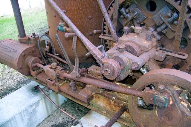
And look at the way that clutch lever is clamped around the actuator. It almost looks like a repair by the local blacksmith but it is actually shown and described that way in the AmHoist Brochure. I guess I will have to try to make one. So I did.
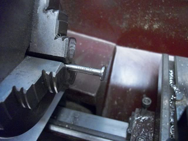
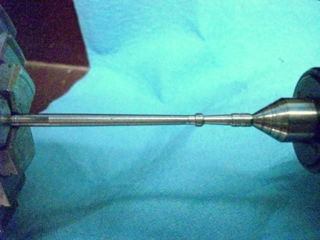
I didn't get any pictures of the process because the batteries in my camera had died so I took this after I got home tonight. It's not exactly right, The clamp bolt needs cutting and the shaft should have been tapered and a little longer and a handle should have been turned at the end before it was bent but those are familiar processes, I needed to see what it would take to fabricate the flat, wrapped clamp. It was surprisingly easy. It took about an hour, but I'm slow when feeling my way in the dark. I'm going to do another one tomorrow. Better I hope.
I guess I'm officially back into this. After all, here is the first new part. Stay with me if you don't mind reading incredibly long posts. They won't all be this long but I feel the need for a full explanation when dealing with things that are out of the ordinary. I hope this explanation was understandable, I don't think pictures would make it any clearer, so I'll try to post a sectioned drawing of the winch shaft with thrust collar soon.
Thanks for watching, comments are appreciated or at least tolerated.
Jerry
.
Is part of the bearing support stand and that the shaft rotates inside of it. I was wrong. In the next view from a different angle and under different light, it is clear that it is not part of the bearing stand, you can see the fine line of separation.
It is fixed to the shaft and rotates against the bearing stand or against a bushing. This is critical. When the clutch pin is pushed in, it pushes the clutch shoes out against the clutch drum but some of that force is transferred to the gear face by the sliders, and the shaft wants to move in that direction as well. I knew that there had to be a thrust collar somewhere but I could not see it. So I had done it wrong. I had used flanged oillite bushings at both ends of the drum. They let the drum turn on the shaft, and they transferred the axial thrust to a flanged bushing in the stand at the far end of the drum. It worked, as I have demonstrated, but it was fiddly and difficult to adjust. It also added a lot of friction to the whole thing. It added enough drag that I felt the need to do some testing to be sure that the engine will have enough power to drive the winch at 200/300 RPM.
I had previously used my Unimat in a to drive the winch in trials, so yesterday, I rigged up a more solid test stand with the unimat drive.
Lowest speed with belt drive.
And reduced to about 200 RPM with a router control box. This box does not give good torque at very low speeds. It is easy to stall the chuck between your fingers. Not very precise but it seems to be in the power range of a twin cylinder air engine.
It took a little bit of fiddling to get the spindle and the crankshaft aligned and a little bit more time to get the clutch adjusted sot that it would engage and disengage smoothly. Playing with this thing is so much fun that I spent some time just playing. I noticed that when the clutch was applied, there was some flexing in the base and that the bearing stands flexed outwards as a result of the thrust being transferred through the winch drum. I was able to lift and lower a 5 pound weight with moderate pressure on the clutch lever but the Unimat motor wasn't happy. It would slow from 200 RPM to less that 100 RPM and get real jerky and stall.
I also noticed an irritating noise from the gears. They have never been run together for more than a few minutes and they had been in a box under the bench for over a year so they weren't bright and shiny. I didn't like the noise and I didn't like the flex so I took it completely apart and put just the pinion shaft and the winch shaft with gear back on the frame. I thought I would let the gears run in with a touch of Brasso and 30weight oil while I scoped out the clutch works.
In just a few minutes, the gears were running very smoothly so I let them run a few minutes more while applying some load with my finger on the big gear. I took them out of the frame and washed them with solvent and reassembled the whole thing for some more observation (playing). Gear noise all gone, smooth as silk. Flex and friction drag still there. I was starting to think that I needed ball bearing thrust washers at each end of the drum but that would be a real lubrication problem.
The quitting whistle blew so I cleaned up and headed to the house feeling a little a let down. After dinner, I was going through my "donkey" files, pictures and drawings, getting better organized to resume this project when I finally noticed the small separation line in the second photo above. Ureeka! That is the answer. That IS a thrust collar. All the axial thrust is absorbed right there. No transfer to the winch drum or to the bearing stand at the far end. I will still leave the flanged bushings at both ends of the drum to keep it in position but the contact between the flange bushing faces will be completely unloaded, even under maximum clutch pressure.
This morning, I turned up a brass thrust collar soldered it to the end of the shaft. I had to adjust some lengths and clearances but I got it all back together. WOW! What a difference. No flex, and without the flex, the additional friction caused by bearing misalignment as the stands flexed out of parallel was gone. The electric motor slowed only slightly as the clutch was applied, even when I increased the weight to 3 pounds. It worked so well that I played with it for another hour, up, down, float, feather, hold, faster, slower, heavier, lighter and I got the feel of the machine and I was not satisfied with the action.
There is no over-center or knuckle-in action. When the lever is at the full end of travel, the clutch linkage comes almost straight but due to the geometry, it will not knuckle in. It has to be held. If you release pressure, it doesn't immediately drop the load, but it begins to slip and soon disengages completely. There is no quadrant or notches to hold the lever either. On the real one there is a stop at the disengaged end of travel but there is nothing at the full on end of travel.
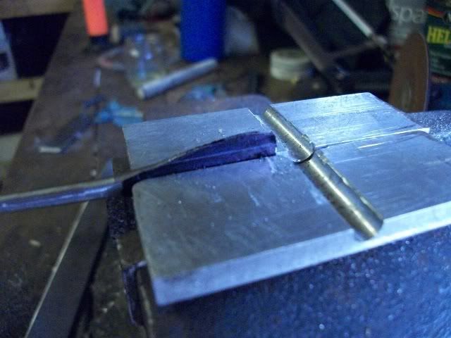
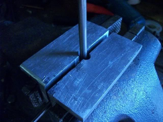
So I start thinking. I redesigned this part of the machine because I don't think that I can cut internal square threads at this scale (or any other scale). I used a slot, milled at an angle across the actuator instead of a full screw thread, creating a straight ramp instead of a helix. I could file of the end of the slot so there is a straight step at the top of the ramp. So I did.
Now when the pin that acts as the internal thread reaches that flat spot at the top of the ramp, it notches in and will stay there until the lever is pulled back. The action is smooth and positive and subtle. No hint of any binding. I did have to readjust the clutch because of the shortening of the inclined part of the ramp. The adjustment is a real pain because it involves taking the drum out of the stands and making small adjustments to the position of the gear on the shaft. I bet they had a better way.
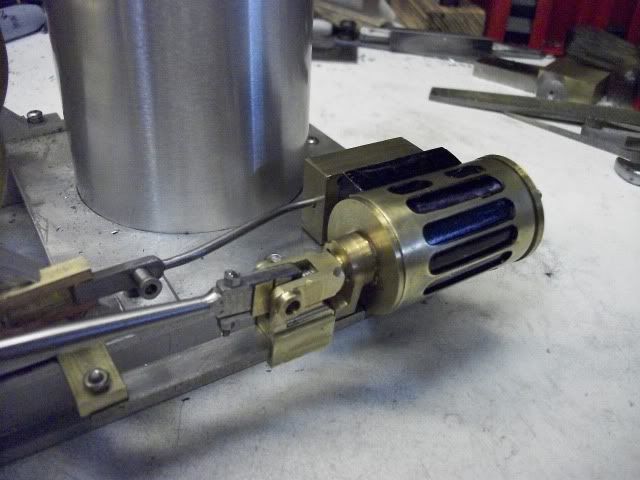
Of course they did. Thats is what the threaded hickey is sticking out of the end of the actuator, a clutch adjuster!
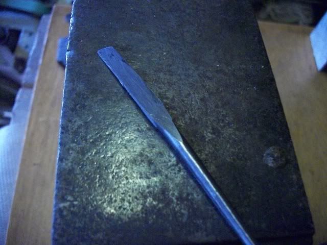
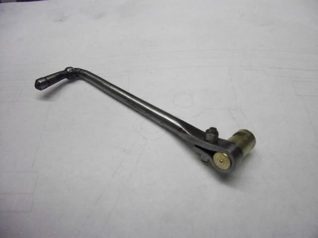
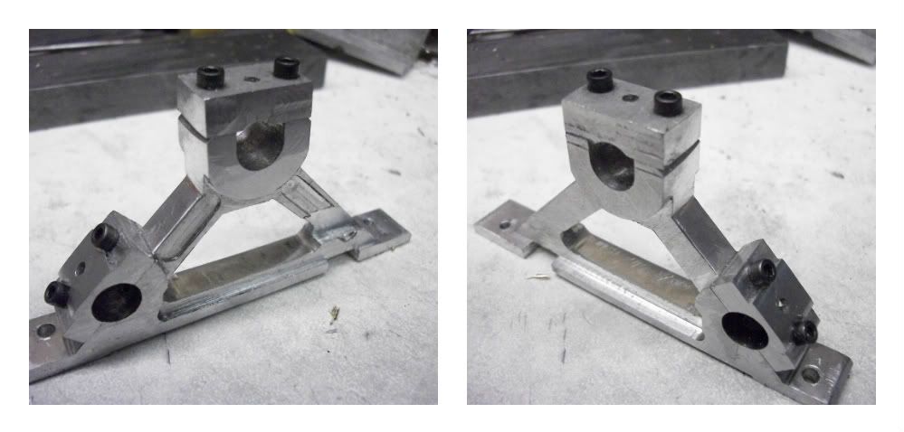
And look at the way that clutch lever is clamped around the actuator. It almost looks like a repair by the local blacksmith but it is actually shown and described that way in the AmHoist Brochure. I guess I will have to try to make one. So I did.
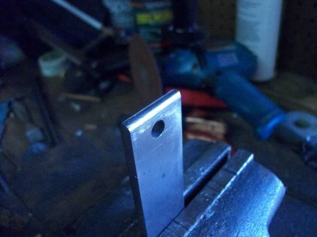
I didn't get any pictures of the process because the batteries in my camera had died so I took this after I got home tonight. It's not exactly right, The clamp bolt needs cutting and the shaft should have been tapered and a little longer and a handle should have been turned at the end before it was bent but those are familiar processes, I needed to see what it would take to fabricate the flat, wrapped clamp. It was surprisingly easy. It took about an hour, but I'm slow when feeling my way in the dark. I'm going to do another one tomorrow. Better I hope.
I guess I'm officially back into this. After all, here is the first new part. Stay with me if you don't mind reading incredibly long posts. They won't all be this long but I feel the need for a full explanation when dealing with things that are out of the ordinary. I hope this explanation was understandable, I don't think pictures would make it any clearer, so I'll try to post a sectioned drawing of the winch shaft with thrust collar soon.
Thanks for watching, comments are appreciated or at least tolerated.
Jerry
.

") You are making good progress and have a good scale loking model there.
You are making good progress and have a good scale loking model there.