Building Jerry's Donkey

Home Model Engine Machinist Forum

Help Support Home Model Engine Machinist Forum:

This site may earn a commission from merchant affiliate links, including eBay, Amazon, and others.
Jerry,
Just letting you know I'm still following your build and learning a lot. Wish there was something I could contribute other than saying, "Well done!". I really appreciate the detailed photos.
Dennis
 
Aha,

The full size picture explains the rod end. It's known as a "block strap gib and cotter."

20/20 vision is known as hindsight. :-[

If one wanted to join the RAN as an engineer artificer back in the 50's 60's. The entry exam was to make one using a lathe, shaper and hand tools plus an oxy set hammer and anvil to form the strap. Time allowed 24 hrs, tolerance +/- 0.002."

If you quenched the strap in water the job was kaput as it was impossible to stress relieve the bend once you started machining and it sprang all over the place. The ones who usually passed the entry were the ones who bent the strap first and left it to cool in air whilst they went on to other parts.

I was lucky, when I sat my final I got the dog clutch. ;D

Memories. ::) ::)

Best Regards
Bob
 
Ahhh a mechanical "inversion"

It's the same thing, just done differantly. The taper key is loosened by loosening the square head bolt a bit. Then carefully set the key with your favorite adjusting tool...sometimes called a hammer....and retighten the bolt to lock the setting.....that would have had to be made with a veritical shaper though...so I don't know if that design won the hearts of the accountants....


Dave
 
Bob, thanks for the acknowledgment. So... you didn't recognize a "block strap gib and cotter" rod end from my poor efforts. Maybe when I get the proper split and bored brasses and the clamp bolts installed they will look more like the real thing. I don't think I can figure a way to install the tapered wedge. I'm still thinking about it.

Dennis, I'm glad your watching. Thanks for leaving a greeting. It's hard to know if its worth the effort without some feedback.

Thanks for the link, Pat J. The Porter discussion explains the engineering behind this rod style very well.

Brian, I did a search for "fish bellied" and turned up a wide range of engineering references, from railroad car frames, to bridge girders, to a Chinese engineering website with a paper title "Numerical Evaluation of Fish Bellied Concrete Box Beam", to this post by Steve Whitehall re building the Stuart "Victoria" with fishbellied rods.

http://www.homemodelenginemachinist.com/index.php?topic=10938.0

Thanks for watching, Woodguy. I think Bob, Dave and Pat answered your question.

While writing this a method of making a working wedge to scale has occurred to me. RATS!! I won't get to try it out until next week. I have to leave early tomorrow and head for the boat. I HAVE A PURCHASE CONTRACT IN HAND!! I have to meet with the buyer's marine surveyor for inspection and sea trials. If all goes well, this happy/sad process will soon be over.

Wish me luck... well not luck but a good outcome.

Jerry

 
I've been following along, Capt. Jerry. I've been enjoying this greatly. Good luck/outcome on the boat deal. I'm trying to sell a boat, too, but so far 90% of the lookers have been flakes, ("Call ya in a few days!" They never do.) so I envy your strong possibility of a sale.
 
Captain Jerry said:
While writing this a method of making a working wedge to scale has occurred to me. RATS!! I won't get to try it out until next week. I have to leave early tomorrow and head for the boat. I HAVE A PURCHASE CONTRACT IN HAND!! I have to meet with the buyer's marine surveyor for inspection and sea trials. If all goes well, this happy/sad process will soon be over.

Wish me luck... well not luck but a good outcome.

Jerry

Jerry,

I know where your at. :'( :D It took me 4 years to sell my yacht and that was at bargain basement prices. I wish you every success with your contract.

Best Regards
Bob
 
Captain Jerry said:
I don't think I can figure a way to install the tapered wedge. I'm still thinking about it.

Jerry,

Yes, very difficult to slot the block and strap at that small size. Perhaps a rod in the end of the block which hits the top half brass with a tapered pin through the block and strap which presses on the back side of the rod. Then again for the running time, bearing load in model format, why not make a false gib using a tapered pin with the exposed ends filed to shape? The bearing wear is not going to be much if it's even measurable.

Hope it's food for thought.

Best Regards
Bob
 
Jerry,
I am watching this with interest because Shay connection rods are the same design with 2 bolts.

I have considered making working ones and the end of the rod only needs a slot cut with an end mill or slitting saw the width of to the taper pin and cut at the taper pin angle. The flat edge of the taper pin rests on the bearing. The slots have to be filed in the strap which will be the hard part.

Bob's sugestion of a filed taper pin would be a lot simpler for a part that is not really needed for a model.

Dan
 
Hi Y'all

OK, I have decided to remake the split bearings.

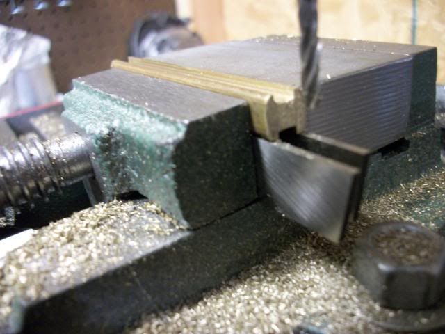
Step 1. Mill grooves in sides of brass bar to match bearing strap:

conrods001.jpg


Step 2. Saw of to length ( 1/2 of finished bearing) 8 pieces:

conrods002.jpg


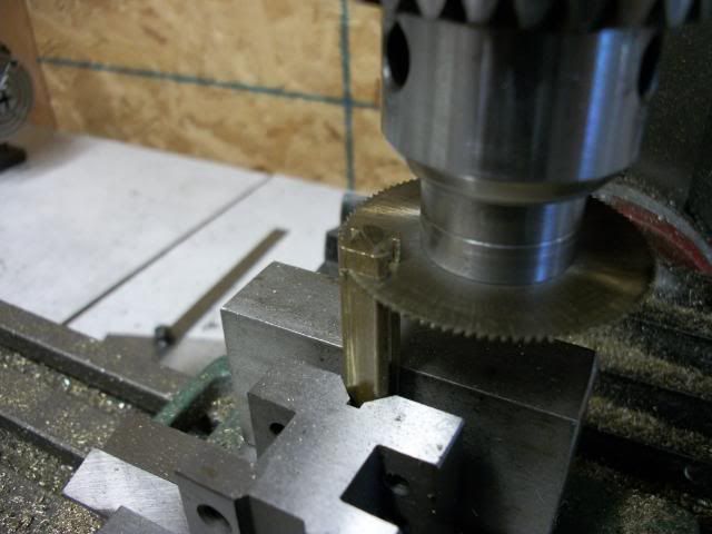
Step 3. Mill slots on 3rd side of bearing halves so that a pair will have groove on all four edges.

conrods004.jpg


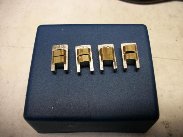
Step 4. Test fit pairs to bearing strap:

conrods003.jpg


Step 5. Test fit to con rod.

conrods005.jpg


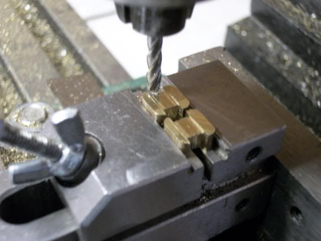
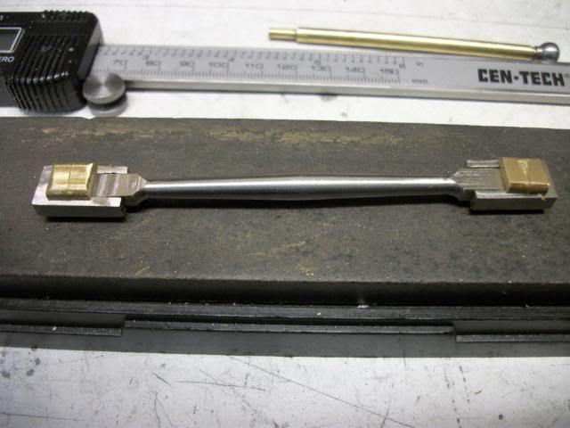
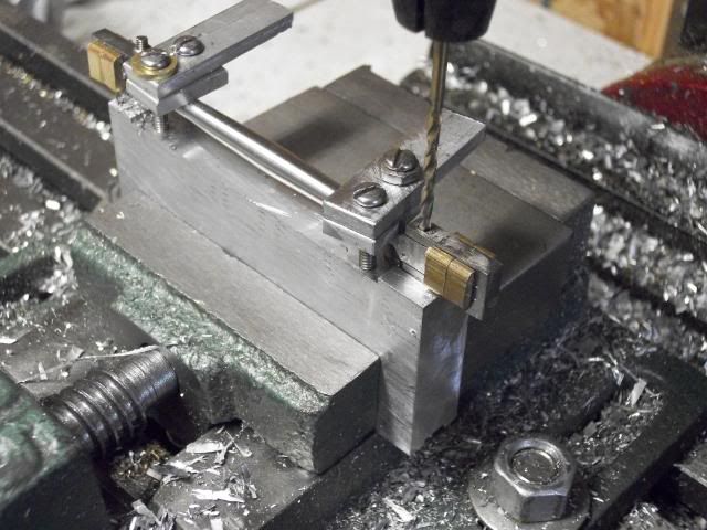
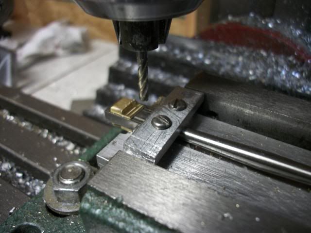
Step 6 Drill for clamp bolts. The fishbellied rod needed a holding fixture to clear the belly.

conrods011.jpg


Step 7. Mill bearing faces to finished dimension. The faces sit proud of the con rod face by .020"

conrods014.jpg


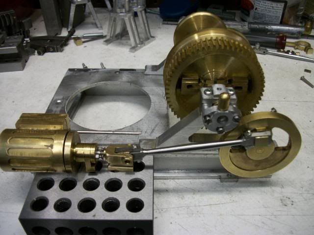
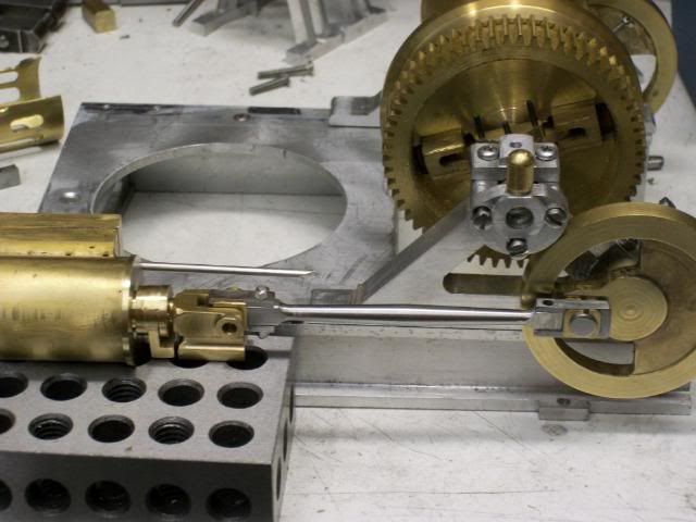
Step 8. Test fit to Xhead guide and orient to assembly.

conrods016.jpg


Oh! crap!!!

The assembly is 1/2" too long. I thought I had more room in there and got a little careless with the packing gland and crosshead support bracket design. I may be able to get some space if I shorten the Xhead a bit but not much. I could cheat the location of the cylinders a bit but not much. I will either have to get it back in a remake of the head, packing gland, support bracket or the frame. I'm Not! remaking the rods!

Jerry

PS. The sea trial went well. Beautifull day, steady winds, great conditions and the buyer was drooling. The surveyor was satisfied with all systems which worked to perfection. Back to the boatyard to haul out for bottom inspection. YIKES! HORROR! The rudder is broken. A huge crack, leading edge to trailing edge, in the middle of the rudder, open all the way to the core. It was not there the last time I was under the boat in the crystal clear waters of The Bahamas. Obvious impact damage but damned if I know when. Coastal and inland waters of the US are so murky that divers who clean the bottom do it mostly by feel and none had reported the damage.

The buyer is still happy and the deal is almost done but I have to provide him with a new rudder. I'll be busy with that for the next few weeks so further progress will be intermittent.


Looking good Jerry, Sorry about the mix-up.

That's a 1-2-3 block? I had imagined it much bigger.

Nice work!
 
Jerry---Tough luck!!! Hope you can find a way around it. This must be the "problem month". I've been fighting crankshaft battles while you've been building your rod assemblies too long!!!---I am enjoying your posts.----Brian
 
Kevin

1-2-3 Blocks are all that size. ??? The bigger ones are 2-4-6 blocks. ;D

(It's after dinner and I'm sipping some good Bourbon that my daughter brought back from Kentucky)

The engine is 1/10th scale. The real one is 10 times bigger. There are times I wish I had chosen a larger scale, but I had brass on hand that dictated the 1/10 scale.
 
Brian

Yeah, stuff creeps up on you. The rods are the correct length. They are one of the easiest parts to get a good dimension on from the original. The problem is with the other parts that I winged it on for some of the dimensions but since the rods were built last, If I had checked first, I could have adjusted. They wouldn't be right, but nobody but me would know. ( Read that somewhere)

I'm following your IC build but since I haven't crossed that bridge, all I can do is watch and learn.

Jerry
 
Actually Jerry....I'm damn proud of ya. :bow:

You didn't let a tough spot change your direction....just figuired out a way to go through it...and then went for it!

You'll get through this hurtel also...I have faith...because you have faith in yourself...They didn't make a Karma point to fit that one, but I'll give one of the regular ones anyway.

GoodOnYa!

Dave
 
I thought they were 1.015-2.035-3.069 blocks, in that case mty sense of scale was bang on.

Just kidding, but my first thought was 2-4-6 blocks.

I'll join you with a shot of Wild Turkey. ;D
 
Problem all fixed and I did not remake the rods. I just had to take a little off of the cylinder heads, the packing gland and the cross head hanger and now I have the full rotation through top dead center. You might not notice but the proportions are now much better.

shrunkthepieces005.jpg


Now that that problem is resolved, I can mount the cylinders in their final position on the base and proceed to fit the x-heads for both cylinder and valve. I did not want to do any of this until I was sure of the cylinder position.

Jerry
 

Latest posts

Back
Top