Building Jerry's Donkey

Home Model Engine Machinist Forum

Help Support Home Model Engine Machinist Forum:

This site may earn a commission from merchant affiliate links, including eBay, Amazon, and others.
Yes, Harris included the ratchets/pawls on his model, along with a brief explanation of their use - well worth including.

Looks like brake linings are 'on' then - I have some of that rubberised cork stuff here that might serve?
 
Hi Jerry
what about Hardwood segments for the brake material ?
might not be doable who knows :)
Pete


techonehundred said:
If you don't want to try leather, Go to the local autoparts store and get some different gasket material. Some is asbestos and some cork. They should be fine for this application.

Well tomorrow I'm off to the autoparts store to checkout gasket materal as advised by Techonehundred, (Thanks)

ShopShoe said:
Sometimes you can get good leather from (discarded) handbags, purses, wallets, etc. I once used some of that to repair an diaphragm type air compressor.

Around here, some of the fabric shops have remainder bins where you can pick up pieces of different fabric and materials cheaply. I once "anti-rattle" lined the toolbox I kept in my car with upholstery vinyl for 25 cents US.

--ShopShoe

and to the fabric shops, as advised by Shopshoe but I'm going to feel a little funny asking the lady at the counter if she has anything to repair a diaphram.

Arnold, suede would seem like a good choice. Maybe even psuedo suede or some kind of imitation.

Pete, I don't think I could get hardwood blocks to work out at this scale but maybe I could use wood veneer strips as used for edge banding. I'll check the home improvement stores.

I may not get much donkey work done for a few days. It seems that my manager has secured a non-paying contract for me to move some cabinets and install new countertops and sink for the grandmother of my son-in-law's son-in-law. Extended families offer a lot of opportunity for recreation.

Jerry
 
Jerry what Dia is the brake drum, as I said earlier wood is often used on traction engines and the engine in my avitar has a 3" brake drum and a series of laminated wood blocks fitted to the band, it would also be easy to go smaller. I'll take a wheel off this evening and take a picture for you.

J
 
Hi Jason
sorry mate that will teach me to only look at the photos :big:
Pete
 
Jerry,

Just get some cardboard off your cornflakes packet and five minute epoxy glue it into position inside the brake band. You will be very surprised how long it lasts.

In the 70's, I used to do a bit of model car racing, and that is what I eventually used in the band brake around the centrifugal clutch (which had a cork liner). Once it has glazed over, it lasts for ages.

Eventual replacement is easy as well, just eat more cornflakes. Or if you want it a little thicker, shoe boxes are about twice as thick.


John
 
They make self-adhesive hardwood veneer edging.
You could try oak or hickory if you can find it.
 
Here you go, the blocks were made by laminating several layers of veneer around a former and then cutting into segments. The blocks are about 3/16" deep as there is an 1/8" recess in the drum rim. Retained onto the strap with expoxy and glued in rivits.

IMAG0298.jpg


Black poplar is the usual choice on full size as it is difficult to burn but don't be tempted to use NA Poplar.
 
John - My breakfast choice is Multi Grain Cherrios. I guess that might work just as well.

Arnold - Thanks for the picture. The brake drum is just under 2.5" dia. Hardwood blocks have always seemed to me to be the right stuff. Mostly because of the remote locations where they were used. I would think that they had better access to a wagon wheel maker than they would to an industrial supply house. Gluing up veneer around a former solves the production problem. The donkey drum does not have a groove but I think there is enough thickness to cut a shallow groove. I'm not concerned with alignment but I want the outer diameter of the band to be at the same height as the pawls.

Thanks for watching.

Jerry
 
Jerry---As soon as I shut my computer off to go to bed, I remembered a question I wanted to ask you and had to turn it back on. Do you have any kind of spring to retract the clutch shoes so they don't drag when not actively engaged? I am working on the clutch for my Donkey right now, and it has occured to me that if I made the bore in the end of the shaft that supports the winch drum deeper, down past the cross pin, I could put a small diameter compression spring, similar to that in a ball point pen, only stronger down into a blind counterbore which would activly push the cross-pin out towards the end which has the activation lever on it, thus ensuring that the clutch shoes will never drag when not engaged.--You may have already devised a method of doing that, but if not, I thought I would share this with you.----Brian
 
The kitchen job was postponed so I got some done today. Cutting ratchet teeth is like gear cutting except an endmill is used. Set up the RT. Center the drum. Adjust depth of cut. 20 teeth requires 20 hole plate, 3 full turns + 12 holes on my 72:1 4" RT.

brakesandpawls009.jpg


The brake drum is 2.4" dia x PI = 7.4" circumference / .375" ( approx tooth space) = 20.1 or 20 whole teeth.

brakesandpawls012.jpg

brakesandpawls012.jpg


Change of subject.

brakesandpawls006.jpg

brakesandpawls007.jpg


Here is a part from the original machine. I'm not sure what part it is but I have two possibilities. It might be the bracket that held the diagonal boiler support stay to the side of the boiler or it might be a support bracket that held the steam valve control valve shaft. It has a part number cast into it, as do all parts of the machine. If anyone has a parts reference for this machine, I will post the part number and maybe you can help figure it out.

I liberated this part a few years ago when I still had a boat in this marina. The part was not attached to anything, just lying on the deck. I told the marina owner that I was building a model of the donkey and asked if I could have it. He generously agreed and he is not known for his generosity.

I have two thoughts on it use. It could just be displayed with the model, as is, or I could try to use the material to produce a part for the model. The part is not pristine. There is a recent scar where someone used a hacksaw on it, not sure why? Before cutting it up for material, I would like to identify the part and if possible, make the same part from it.

Any thoughts or suggestions?

Jerry
 
Brian

I have not incorporated a spring to retract the clutch. I had thought that I might do it the way that it was done on the original. AmHoist use small coil springs, radially between the shoe and the gear plate. You can see the spring in the upper left corner of this picture.

Donkey006.jpg


I had thought that the model train shops might have something suitable but I don't think it is necessary. Extensive testing (playing) with the clutch mechanism shows no tendency of the clutch to hang up and not disengage, even under heavy loading. The operation of the clutch is so smooth and reliable that I am reluctant to make any modifications. I have thought that a spring washer between the gear face and the cross bar could be used. I'm not sure that I used the right term for this spring but it looks like a bent washer made of spring steel or beryllium/copper.

Jerry
 
I am in Awe, thank for posting your progress so far, its fascinating to see the set ups you use for small parts and its looking amazing!

Zac
 
Whats under the hood? Here is a quote from the Amhoist brochure.

Hoodofdonkey.jpg


Here is a little exercise that I tried yesterday. It proved the method so now I will do it again with a bit more care. The top of the boiler is a mess of pipes and valves and the hood is just a tin roof to keep debris out so I thought I would try a little tin work. I wasn't sure what was going to happen so I only got pics of the results. I didn't do a thorough layout job but it doesn't take much. Just layout a circle with a radius equal to the hood width (on the slope). Cut it out with the snips and then make one cut from the edge to the center. It helps to have a punched or drilled hole at the center. Then just roll it into a cone with your fingers and when the slope looks right, tape it to hold and rivet the edge.

Funnel006.jpg


Funnel007.jpg


That's about it. There will be a little more when I get to the piping.

You might notice that the donkey base is empty. Since restarting this project, it was clear that the previous base was inadequate for the installation of the mechanism to operate the brakes and pawls, and also poorly designed (in my model, not the original) to add the front drum, which is a bolt on assembly, so the base has been redesigned and rebuilt. I'll get some pics of that tomorrow

Jerry


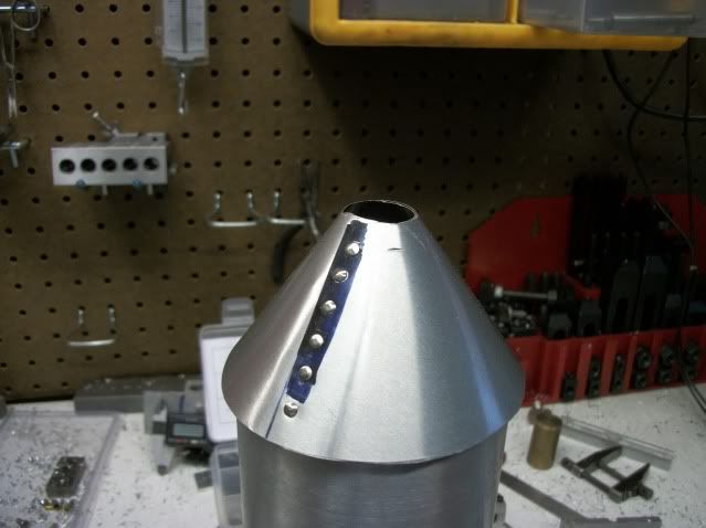
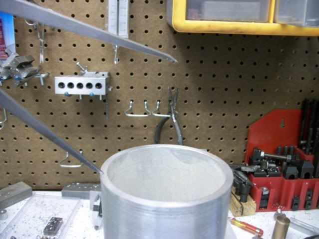
This is the current state of the hood.

hood021.jpg


The previous was just a test of the process and it worked ok so I started over with a little more care. The material is aluminum roof flashing available is several sizes at home improvement stores. I have always called this stuff roofing tin so in the interest of saved keystrokes I'll just call it "tin" from here on. It is easy to cut with heavy scissors but when formed into the funnel cone. The first step is to layout a circle with a radius equal to the distance from the edge of the boiler cylinder to the apex of the final cone.

Here I am using dividers to pick this dimension by eye.

hood001.jpg


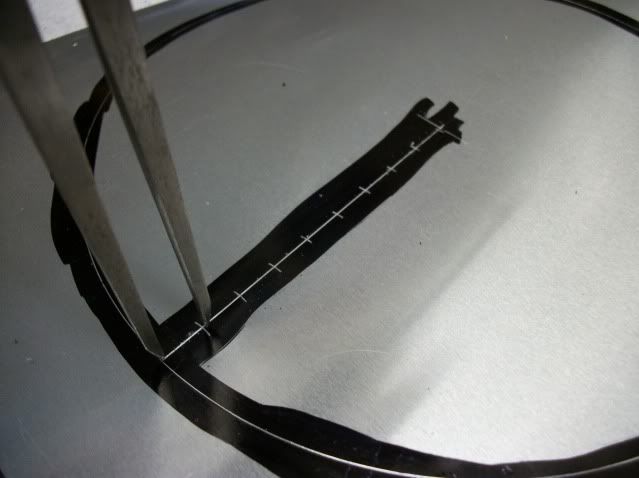
Adding a little for overhang yields a dimension of 3.6" which I used to scribe a circle in the tin. I then scribed a radial line and stepped of 3/8" increments from the edge to the center for rivets. A second line, parallel to the radial line, is scribed for cutting.

hood003.jpg


The circle is cut with shears and then holes are drilled at the center and at each rivet location. For the rivets that I have the bit is 5/32". The surface is very smooth and the drill bit will wander so the locations must be punched but VERY lightly so the sheet is not distorted.

hood004.jpg


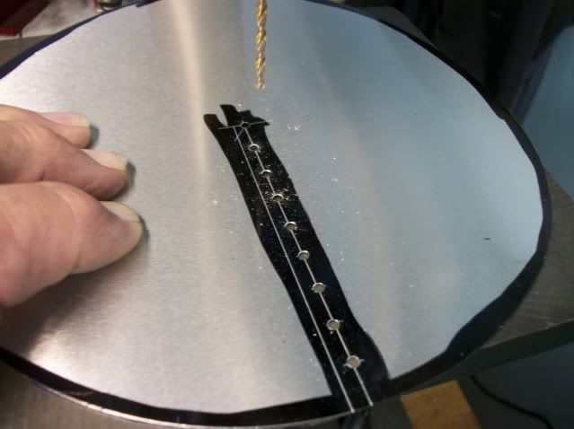
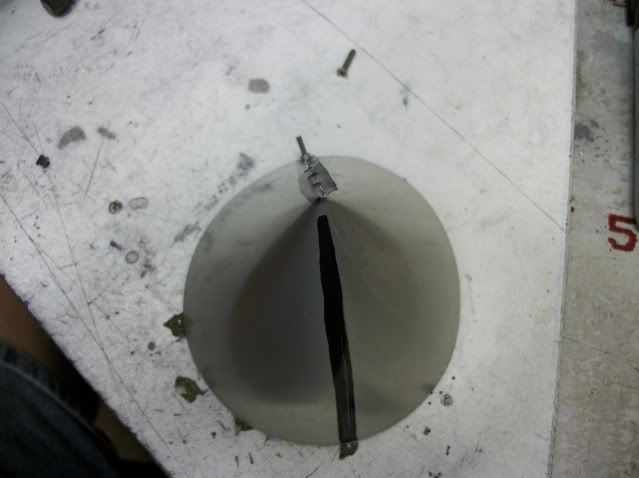
The tin is then cut along the line parallel to the rivet line. This line does not intersect the center hole so as the shears pass the last rivet hole, the cut takes a right turn and cuts int to center hole. IMPORTANT! The cut must not cross the center hole and nip the far side of the hole. If the for side of the hole is cut, you will have a very difficult time forming a regular cone without distortion.

Using your fingers, offset the cut edges and slide the tin into a cone shape, being careful not to kink or fold the tin. Continue to slide the tin tighter, until the cone is to the desired shape. Trust your eye, but the base of the cone should be just a bit larger than the boiler cylinder. I am quite capable of working out the math and geometry to cut a pie shaped wedge out of the circle that would yield a cone but the overlap method yields a smoother, stronger curve. With the cone formed to the right shape, using a sharp scriber, mark through the outer rivet hole to locate the mating hole.

I guess I lost my concentration here and forgot a process picture of this next step. Now lay the circle out flat and locate the marked location. Scribe a radial line through this point to the center, and step off 3/8" increments for rivet holes. Punch lightly and drill the holes.

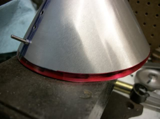
Now the cone can be reformed and secured with a #2-56 bolt and nut. Do not rivet yet! There are more holes to mark and drill but first, note that the inner layer of tin hangs out slightly past the outer layer as shown here in red.

hood007.jpg


Mark this overhang with a sharp scriber, uncoil the cone and trim the excess before reforming the cone. Now we're ready to mark and drill the second row of rivets 180° from the first row. Mark the location with a magic marker as shown here.

hood006.jpg


Only one line is shown in the pic but I decided that four rows of rivets would look better so I made marks at 90° and 270° as well. Now unroll the cone and use the marks to scribe lines and step off the rivet hole locations, punch and drill.

These are only the exterior layer, so once again, form the cone, secure it with the bolt and use the outer ring of drilled holes to mark the locations on the inner layer. Be sure that the inner layer of tin is tightly pressed to the outer layer when marking.
I know this is getting very repetitive but again unroll the cone, pick up the marked locations, step off the rivet locations and drill.

WAIT! BUT FIRST! Before uncoiling the con in the above step. it is time to mark the location of the stack pipe which must be cut. I am using a piece of 1/2" brass pipe (ext diameter .875") for the stack pipe so I set the pipe down on the cone and scribed around it. When the cone is unrolled for the last time, this line is cleaned up and cut very carefully, using my wife's finest scissors (you know better).

Now the cone can be formed for the last time and riveted. Where did I get the rivets? At the junk yard (salvage yard)! No kidding! They have bins full of the little buggers. They are plated steel but they will be painted so why not. If I had the right sized copper rivets I would use them but I don't

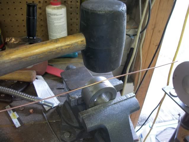
Just a few more steps to finish. The cone is fairly stable but just needs a stiffener ring around the base for ridgidity and appearance. 12 guage copper wire is just the ticket, strong enough and easy to form. To get it into a smooth regular shape, I resort to one of my favorite tools, hammer and anvil.

hood011.jpg


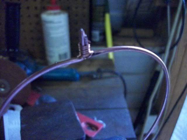
Well rubber hammer and round anvil. The rubber hammer eases the wire into a smooth circle without marking the surface. It doesn't have to be beat to final size, just to near size. Final size is to fit the base of the cone with enough extra to bend up some ears for soldering.

hood012.jpg


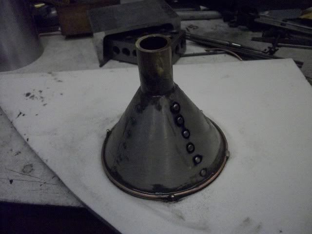
Soft solder is fine for this. After soldering, it is closely trimmed and filed. Here it is on the cone. It has been fileted with J-B Weld and small nails are used to keep it forced to the edge of the cone, holding the circle and cone on a piece of scrap of HDPE (Starboard).

hood013.jpg


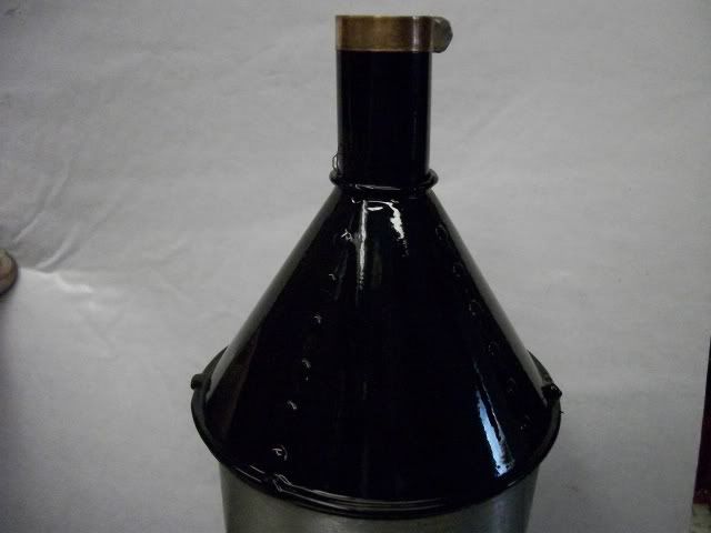
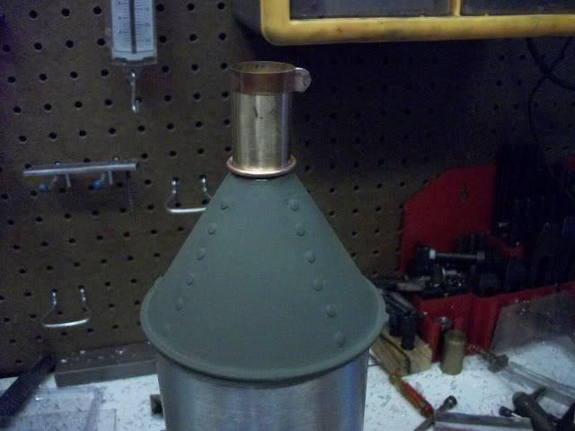
Here it is with a coat of primer. Another copper ring is in place to blend the transition to the stack pipe.

hood016.jpg


And one last pick with paint. way to glossy I think. If anyone has a good experience with a not too glossy black paint, I would appreciate a suggestion.

hood021.jpg


This has been a very long post. Almost longer that the build.

Thanks for watching.
25920
Jerry


Very Nice Hood :bow:

(Robin would be proud to wear it)

Best Regards
Bob
 
Nice bit of tinwork Jerry.

I used to hate doing plate development layout in my earlier years (a little bigger than that though, full sized stuff), I think maybe because I never seemed to get it quite right, and always ended up slightly the wrong shape or angle first time around. Tin snips and a hammer soon put it right though.

Just a thought, if you were to make another one, or someone doesn't quite have your abilities, a plastic funnel from the supermarket would maybe work just as well, seeing that it is non functional and also painted afterwards. What the eye doesn't see..........


John
 
Bogstandard said:
Nice bit of tinwork Jerry.

I used to hate doing plate development layout in my earlier years (a little bigger than that though, full sized stuff), I think maybe because I never seemed to get it quite right, and always ended up slightly the wrong shape or angle first time around. Tin snips and a hammer soon put it right though.

John

My experience with developing cones from sheet metal parallels Johns!!! yours however looks very good, Jerry!!
 
Captain---In regards to non glossy black paint.---A trip to your automotive store should yield cans of "chassis black" in aerosol cans. This is a black that is not absolutely flat, but doesn't have a high shine to the finish.
 
Maryak said:
Very Nice Hood :bow:

(Robin would be proud to wear it)

Best Regards
Bob

I hadn't thought of it as a fashion statement but it might work down under.
http://upload.wikimedia.org/wikiped...-Hamlin.jpeg/399px-Tin-Man-poster-Hamlin.jpeg

Bogstandard said:
Nice bit of tinwork Jerry.

I used to hate doing plate development layout in my earlier years (a little bigger than that though, full sized stuff), I think maybe because I never seemed to get it quite right, and always ended up slightly the wrong shape or angle first time around. Tin snips and a hammer soon put it right though.

Just a thought, if you were to make another one, or someone doesn't quite have your abilities, a plastic funnel from the supermarket would maybe work just as well, seeing that it is non functional and also painted afterwards. What the eye doesn't see..........


John

My first thought was a store bought funnel. I used to have a nice drawn aluminum funnel that I used to change oil on my generator but it may have been among the last metal funnels made. I searched the usual sources, including second hand stores, but came up short. Plastic? OK for changing oil but my donkey deserves better.

I spent the summer, half a century ago, as a helper in a sheet metal shop, when ductwork was made of galvanized steel. I was also an engineering student at college, so the layout of transition pieces that joined rectangular duct to round was very interesting to me. Otherwise, this was one of the worst jobs I ever had. Wrapping ductwork with fiberglass insulation in an attic where the temp was over 100°F is something you don't forget.

Brian Rupnow said:
Captain---In regards to non glossy black paint.---A trip to your automotive store should yield cans of "chassis black" in aerosol cans. This is a black that is not absolutely flat, but doesn't have a high shine to the finish.

Thanks for the tip, Brian. I'll check out "chassis black"

An thanks for watching.

Jerry
 

Latest posts

Back
Top