Building Jerry's Donkey

Home Model Engine Machinist Forum

Help Support Home Model Engine Machinist Forum:

This site may earn a commission from merchant affiliate links, including eBay, Amazon, and others.
A small update. The donkey is proceeding but slowly. One of the problems of reviving a project after a long period is that many of the parts made previously don't look as good to me as they did at the time that I made them so a lot of the parts are being remade. This gives me an opportunity to relearn some of the lessons that I learned in making those old parts.

I don't know if everyone agrees but there has been a lot of very fine work displayed on this forum lately. The level of detail, artistry and finish of several of them has made me re-evaluate my focus. I don't want to reverse this trend but I will show a few pictures of the state of the project.

whatzit056-1.jpg


whatzit057.jpg


As you can see, I have decided to return to the original two drum plan. Every time I open the parts box for this engine, that second gear and clutch drum look up at me. I just cant ignore them. The front frames need to be profiled but I wanted to verify gear mesh first.

Along the way, some other detail captures my attention, and I take a little side track, like these ash clean out doors.

whatzit058.jpg


whatzit059.jpg


Thanks for watching.

Jerry
 
Very cool detail Jerry. Thats what I was planning on doing next to my own donkey, if those elbows from PM Research don't appear here soon.---Brian
 
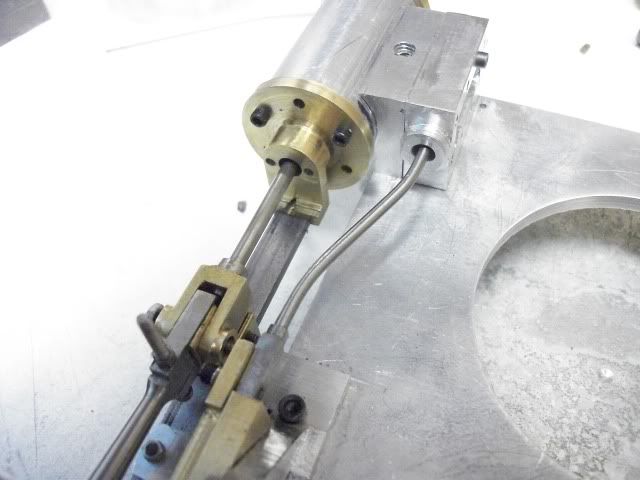
Here is today's effort. The right front frame has been profiled to shape and attached to the main frame.

frontframeassembled007.jpg


There is a little more fine tuning to the shape but it is close. The boss surrounding the shaft bearing is 1" diameter and will be reduced to about 7/8" after the clutch actuator assembly is mounted and the bearing cap will be profiled to match the rear hoist bearing cap. I didn't get to left hand frame. that will be for tomorrow.

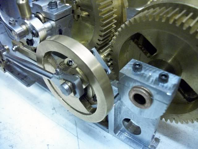
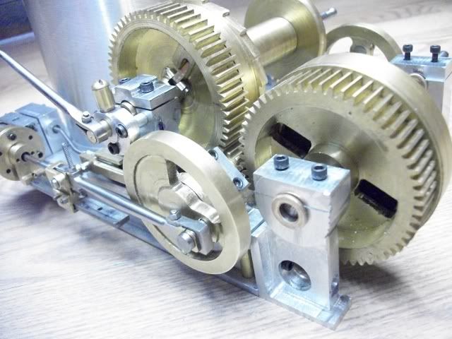
I also decided it was time for a partial assembly to check clearances and alignment. The main things that I needed to check was clearances, alignment and gear mesh.

frontframeassembled012.jpg


All went well except that both eccentric straps needed a stoke or two of the file to reduce the thickness and eliminate some binding. The gear mesh of the front drum to the pinion was what I was most worried about and a little file adjustment to the mating surfaces on the front of the main frame and the rear of the front frame. It is now perfect. (I'll be the judge of that)

Another big reason for the assembly is to help visualize the location of all of the mechanism inside the frame. There are two brake linkages, operated by foot pedals, and two ratchet linkages, operated by hand levers. The ratchet pawls are lifted into the ratchet teeth through a coil spring so that it can over ride in one direction and lock in the other direction.

I don't have any plans for this and the machine that I am using for reference has lost almost all of this through age and rust. It is also very difficult to get under the thing to do any measuring.

Thanks for watching. 27329

Jerry


O Captain! my Captain !
What a wonderous piece of work - I don't know why I haven't read this thread before - my appologies for not chipping in sooner - the thread predates my signing on.

So I've spent an hour plus going through this and Brian's Donkey engine thread.

I see someone asked (but was never answered) why a "donkey" engine - I presume because it was used to repace mules in haulage applictions - or am I off beam here ?

Definitely interested in plans - should you care to post them in the downloads section.

Regards,
Ken

 
Ken

This project is so old that it predates a lot of things. I'm glad you dropped in. There has been some discussion of the term "donkey" and I am mystified why it isn't called a "steam horse" or a "steam mule" which are the animals that it replaced in the logging industry where they were used. Maybe its because, like a donkey, it can refuse to work for no apparent reason, or maybe the donkey had a better public image in the late 1800's when they first appeared.

They got their start in logging but were also widely used in mining, heavy construction, industry, and marine applications. They did so much more than just drag logs out of the woods, and there are lots of things that can be put on the end of the cable besides a hook. When I picture this machine at work, I see it mounted on a barge with an "A" frame boom and either a clamshell bucket or a piledriver but that's just my point of view.

Thanks for watching.
27621
Jerry
 
Not yet Brian. Funny you should ask as I was just thinking about that today. One reason I was thinking about that part of the came for the recent trial assembly. I have recently changed from a 3" aluminum pipe to a 3 1/2" aluminum pipe for the faux boiler. To be true to scale, it should be 3 1/4" but you use what you can find. The bigger pipe looks better but when it is positioned on the deck there is no room to remove the steam chest covers. I think you mentioned this problem. I had not thought too much about this until I realized how difficult it was going to be to move the boiler after the piping is fitted. I plan to shave about .050" off of the valve face on the cylinder and about .020" off each side of the steam chest so that will increase the clearance by .090" on each side. That is still not enough space to work but it will look better.

The biggest problem that I have to deal with is the way that American Hoist designed the valve rod and the guide. The rod is a single piece, from the valve to the guide which is on the hoist frame and it has a large bend. When the rod is disconnected from the eccentric rod, there is no room to rotate the valve rod a full turn to adjust the valve, because of the bend.

The usual method of using a small bar with a tapped hole captured in a channel on the valve is going to have to be changed. I need to be able to adjust the valve nut instead of rotating the valve rod, and I need to be able to do it without removing the steam chest cover.

I have a plan but I won't get to it until next week.

You have said 'engines' before but since there is only one crankshaft, I think of it as one engine with two cylinders.

Jerry
 
Don't get too hung up on an exact, authentic scaled down model. There isn't anybody left alive today who really remembers exactly how these things looked/went together. The world of model building is a lot like the world of hot rodding----If it looks right, then it probably is right!!!
 
Captain Jerry said:
This project is so old that it predates a lot of things. I'm glad you dropped in. There has been some discussion of the term "donkey" and I am mystified why it isn't called a "steam horse" or a "steam mule" which are the animals that it replaced in the logging industry where they were used. Maybe its because, like a donkey, it can refuse to work for no apparent reason, or maybe the donkey had a better public image in the late 1800's when they first appeared.

A donkey could be described as an auxiliary horse

donkey boiler - auxiliary boiler

donkey engine - auxiliary engine

donkey man one who looks after and or operates the auxiliaries.

Best Regards
Bob
 
Last week, I said that I had to come up with a different way to adjust the valves on this engine. That's because the one piece valve rod with a bend can't be disconnected and rotated to change the length. Here is what that looks like.

donkeyvalveadjuster009.jpg


Even if there was room to make a full revolution of the rod, the 56 TPI thread would move the valve about .018" which might be a little coarse for best performance so instead of rotating the valve rod, I decided to rotate the valve nut. The usual valve nut is a tapped bar that lies in a slot in the valve and can only be rotated in increments of 180° and then only by loosening and lifting the valve chest clear of the valve face. So I decided to replace the valve nut with a spool that can be infinitely adjusted. It is accessed by a screwdriver through a port in the back end of the valve chest. The port will be sealed by a screw in plug after adjustment is made. The initial adjustment will be made by eye with the cover off and the fine tuning carried out with the cover on after test runs.

Here is a video of the valve being adjusted.


To keep the spool from rotating under use, the spool/rod thread is made TIGHT! I can't do much about the tap but when threading the valve rod, I used and adjustable die that was opened to produce a slightly oversize thread. That, plus the length of the spool should be enough to keep it in place. The adjustment takes some effort to turn.

I don't think that this is an original idea. I can't remember if or where I have seen it used, so if it was your idea, "Thank you, whoever you are," but if it turns out to be original, "You're welcome."

Thanks for watching.
28162
Jerry
 
A wonderous creation you are making there Jerry.

When it is finished, people will be able to admire it for what it is, a good representation of an engine long gone, and I am sure no-one will pick you up for using a tiny bit of artistic licence in recreating missing or unseen parts.


John
 
Hello Jerry,

Fascinating project. So glad that you are working on it again.

Is the access port in the valve chest for the screwdriver slot on the opposite end as the valve rod? I was wondering if you couldn't drill and tap that end for a socket head set screw to lock your spool in place after the adjustment. It looks like there may still be enough of a screwdriver slot left at the outside to adjust the spool after a set screw in installed. You have probably already considered this, but thought I'd mention it just in case.

Thanks for sharing your project. It is very interesting watching the design and problem solving as you progress. Great job documenting it too.

Kind regards,
Mike
 
John, KRV3000, and Mike

Thanks for posting your comments. I have taken so long to get to this point in the project and am making such slow progress that I fear most of the viewers have been put to sleep. This may be the project of a lifetime but only because of the slow pace.

I did think about using a locking screw in the spool as you suggest, Mike. The spool is tapped for the full length so it could be done easily and there is plenty of room for it. But I really think it is unnecessary. The spool is a very tight fit and if I don't wear out the thread with to much fiddling, I think it will hold. This is just the first attempt and will be refined. You can see the cross slot that previously held the regular nut.

Thanks for watching.

Jerry
 
Captain Jerry said:
I have taken so long to get to this point in the project and am making such slow progress that I fear most of the viewers have been put to sleep. This may be the project of a lifetime but only because of the slow pace.
Not at all Jerry ;D - just following along without additional comments to add except for that you're doing a great job :bow:
Build it at your own pace - it's not a race; just a pleasurable pastime Thm:

Kind regards, Arnold
 
Jerry,
This build finally caught my attention. Very impressive work.
Alan
 
Jerry,

I am still watching with much growing greatest interest and I for one have not, and COULD NOT, fall asleep with this!
Don't you dare stop showing your posts/build.

Kind regards,

Ron.
 
I'm still here as well - I really want to do one of these, but not until I've got a few other half done things out of the way
 

Latest posts

Back
Top