Building Jerry's Donkey

Home Model Engine Machinist Forum

Help Support Home Model Engine Machinist Forum:

This site may earn a commission from merchant affiliate links, including eBay, Amazon, and others.

Captain Jerry

Project of the Month Winner!!!
Project of the Month Winner
Joined
Dec 2, 2008
Messages
971
Reaction score
8
SteamDonkey005.jpg


I think I am committed or should be. This may be more than I can handle, but I am going to go for it. I have photographed, measured, modeled, cogitated and procrastinated as l long as I can. I think I have identified the more difficult parts and I feel confident that with a little bit of help, I can get through this.

I have not purchased any plans or books that detail building this kind of model, with the exception of a copy of the original manufacturers brochure, not from any purity of purpose, but just because I get the greatest satisfaction from solving problems rather than repeating someone elses solution. That does not mean that suggestions and observations are not welcome. They absolutely are! I just wanted to start with a blank slate. Well not really, I've done a lot of drawings and plans but there will be obstacles ahead that I can't see from here. so please comment If you see me headed down the wrong path.

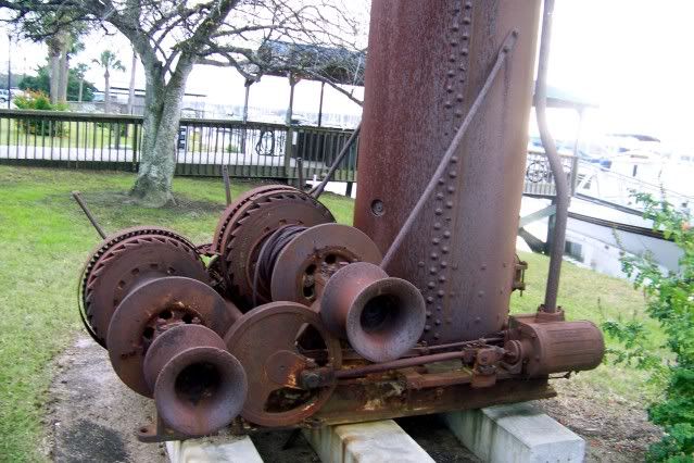
Today I built the first part. I want to build this thing from the bottom up so I started with the base. From what little I have seen of other donkey models, the seem to use formed channel to fabricate the base. I don't know if that is right or wrong, but the example I have to go by seems to use castings for the base elements. The components of the base are either welded or bolted together. The first clue is that the side and back rails include lugs that extend beyond the edge of the lower flange that were used to bolt the unit to the deck or skid. These lugs do not appear to be welded. Also, on the top of the front cross beam, the manufacturer's name "American Hoist & Derrick Co., St. Paul, Minn." appear in well formed raised letters. That's a casting.

I'm not going to start casting. This will be all bar stock or plate but it does make a difference. If the base were channel, you would just drill or burn a hole for mounting bolts. Most available aluminum channel or angle extrusions are to thin to suit this. A trip to the junk yard yielded a 12" length of heavy 6" extruded channel. The back and flanges are 3/16" thick and the flanges are 1.5" wide.

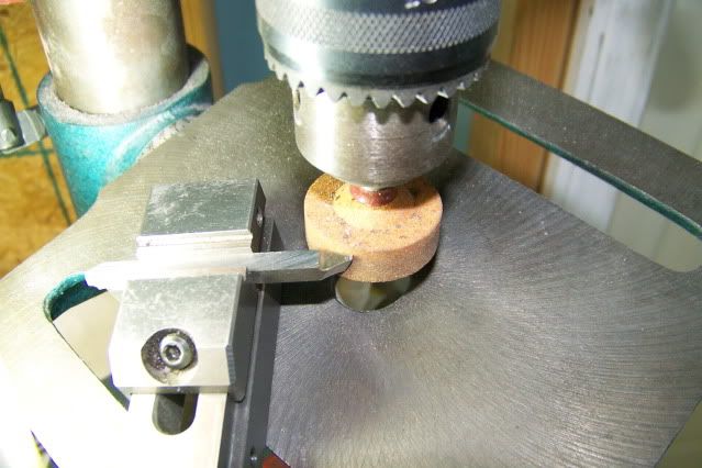
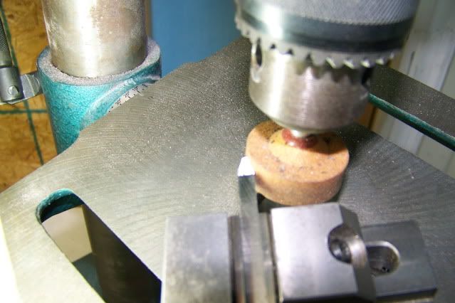
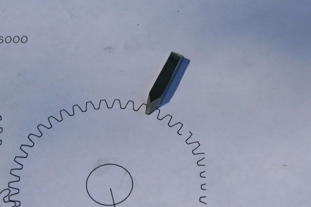
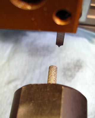
A slitting saw would make this into the material I needed. Slitting saws are expensive so I used an inexpensive alternate. Harbor Freight sells a little (very little) cut-off saw for about $30 that uses a 1.5" dia HSS blade that is very thin. The blades sell 3 for $9.95. Sorry, forgot to measure and the shop's closed, so very thin. Very fine teeth and hollow ground. With a little care, it produces surprising results, Here is a picture of it ripping slices from the channel, making angles.

Jerrysdonkey017.jpg


The thin blade is flexible, so if it is crowded, it will tend to warp and run of line and bind. I make the first pass just to the depth of the teeth, feeding into the cut. I increase the depth of cut on the return pass. (climb cutting), but the grove left from the first pass is full of WD40 so the cut is smooth as fast as I can crank. The next forward pass is to full depth and feed is only a little slower with an occasional spray of WD40. The finish cut is as smooth as you could want.

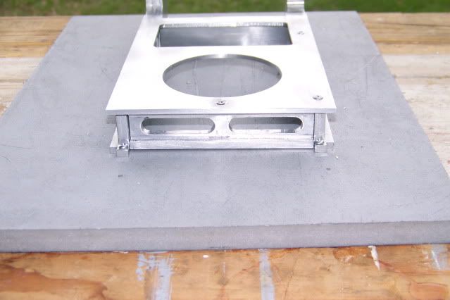
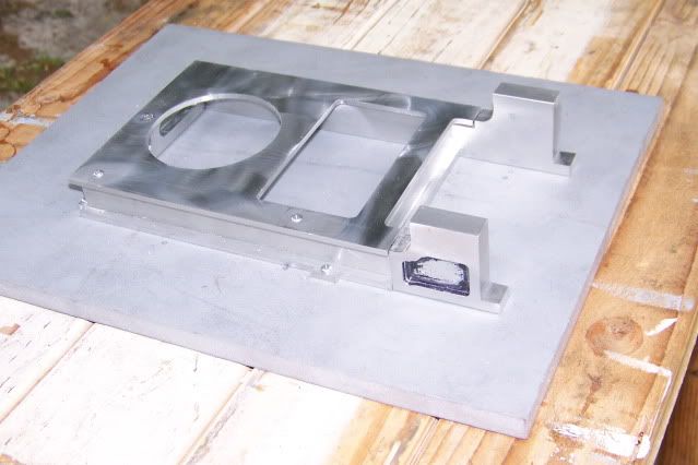
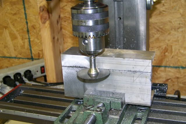
Once the pieces are a little more manageable, ordinary milling techniques yield the finished parts. I show them here screwed down to a piece of high density polyethelene (HDPE) using the above mentioned lugs. Here is the base:

Jerrysdonkey022-1.jpg


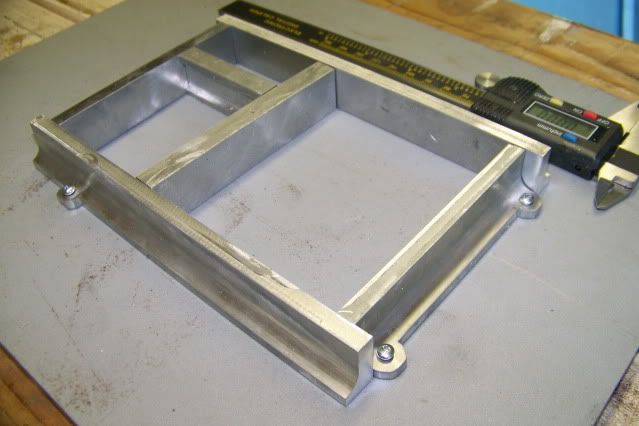
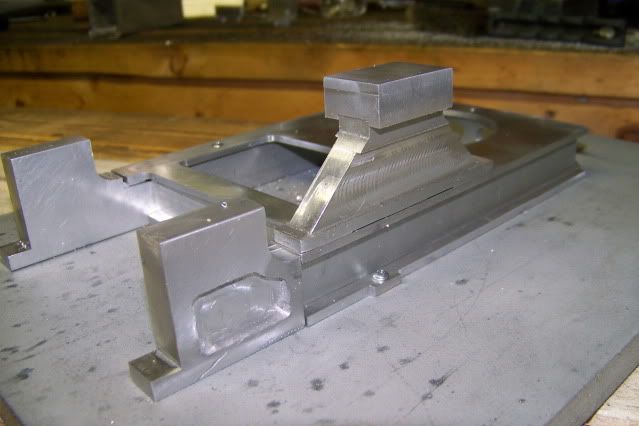
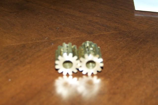
Here is another shot with the boiler (paint can) and hoist gears (not yet), just for scale.

Jerrysdonkey025-1.jpg


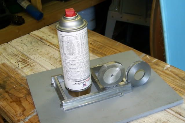
By the way, I have decided to use 1/10th scale. The finished model will be just over 9" long and 5" wide including the front hoist drum that mounts on a bolt on frame extension. At this point, I plan to build the model to run on air, with a simulated boiler for appearance. Whether or not I build a working boiler at a later date is undecided.

Start the clock, it's under way. Next will be to add the deck plate.

Jerry

 
Jerry,
Congratulations on deciding to go for it. This will be a fun build to follow. Great start, too!
Dennis
 
All right! Looks like you've got a good start. I'll be keeping an eye on this.
 
Jerry,

Onya mate, watching with great interest. :bow: :bow:

Best Regards
Bob
 
Great start Jerry...This will be a fun one to watch!

Bill
 
Jerry,

I'll be following your build closely.

I have a feeling that I will learn a lot from this.

SAM
 
Deck plate. Should be simple. Just a rectangular piece of 1/8" aluminum plate with a round hole and a rectangular hole. Simple until I got started. How do you hold a 6" x 8" plate in a 2.5" vise. I decided to bolt the plate to a 2.5" x 2.5" x 3/8" aluminum plate, grip the square piece in the vise and mill th plate to dimension. Second complication. How do you mill a finished 4.8" x 6.75" plate on a mill that only has a 4" Y travel. Lots of head scratching and no quick easy solution. I wound up having to move and re-square the vise three times. That let me get the plate to finished dimension. The plate was then bolted down to a sacrificial plate of HDPE and then milling out the rectangular hole with a 3/16" end mill. The round hole was cut with the end mill by pivoting the plate and the sacrificial plate around a bolt held in the vise with a v-block.

Sorry about the lack of pictures. This was a messy and unattractive procedure and probably not a good example for anyone to follow. I did take some pics but forgot to take my shop chip out of the camera and the pics got deleted by my wife at my great-granddaughter's birthday party. Just as well.

Here is the present state of the project. Base with deck plate, two front hoist frames, and one main hoist frame. The frames are just roughed out for fitting. They will have additional detailing added when I receive the ball-end mill and rotary table that I have on order.

Jerrysdonkey031.jpg


Jerrysdonkey030.jpg


Jerrysdonkey033.jpg


I have come to the conclusion that this project cannot be completed without a rotary table/indexer. This project is really about the hoist mechanism and the hoist mechanism is geared. Yes, I could buy gears and I would if the gears were incidental to the project but in this case, they are central to the project, so If I can't make the gears, I should pick another project.

So in the coming weeks, I will either make a set of gears or make a sharp right turn and look for another project. Watch me if you want to. I promise to take pictures.

Jerry
 
Just curious. Does anyone know where the term "donkey engine" came from?

Tom
 
Jerry,
The base if looking great so far, and even with the limitations in travel/vise capacity, etc. it looks like a nice job. I wish you success in the gear cutting and will be watching for that as I hope to cut two gears for my current project. I suspect that once you get that rotary table you will wonder how you did without it :big:

Keep up the good work!

Bill
 
Jerry,
This is a great start to a tough project. I like your attitude on making the gears. Lot's of pictures please. Gears are a demon I've got to face one of these days, too.
Dennis
 
I don't have the rotary table/indexer yet but I am going to start on the gears. Here are the gear specs.

The hoist gears (2) will be 24 Pitch, 60 tooth, 14.5 PA , 2.5" pitch diameter, 2.6" blank diameter, 1.19" tooth
root diameter, .496" tooth face radius, 36.3 degree tooth face angle, .5" tooth face.

The pinion will be 24 Pitch, 12 tooth, 14.5 PA, .5" pitch diameter, .582" blank diameter, .396" tooth root
diameter, .0992" tooth face radius, 54.7 degree tooth face angle, .5" tooth face.

I hope I don't have to make many gears so purchased cutters are out. I'll go with a tool bit in a flycutter for the
tooth profile. Grinding the cutter would be a lot easier if I new what it was supposed to look like so thats where
I'll start. There are several gear vendor web sites with a bunch of free information. This is the one I used:

http://www.rushgears.com/Tech_Tools/PartSearch5/partSearch.php?gearType=SPUR

It has a table that lets you design a custom gear and then download a detailed CAD file. The download comes in a
variety of flavors so I used the .STEP format and imported it into ALIBRE as a new part and then created a drawing. All of the critical dimensions can be read on the drawing.

As a rookie, it seems to me that the most difficult part of grinding the tool would be getting the radius of the
tooth face and the apparent angle of the tooth faces. I don't really see this angle specified in any gear tables.
It is not the same as the pressure angle which is the same on both gear and pinion. The angle that I am referring
to is greater on the pinion than it is on the driven gear. It can be constructed by drawing a line through the
ends of the arc on opposing tooth faces and taking the included angle. It is easier to do than to say so take a
look at the drawing.

12toothpinion60toothhoistgear-2.jpg


I will use this to form the first operation on the tool blank. Just grind a pointed tool to this angle on the bench grinder, with appropriate relief angles. I'm using 3/16" HSS tool blanks.

Once you get the tool to the pointy shape. then grind the face concave to the right diameter. On the big gear, the angle is 36.3 degrees, and the tooth face radius is .496". To get the radius on the tool, just dress a mounted
point to a diameter of .983" or just slightly less than 1". Then just a few touches of the stone to the flat face
of the tool from the previous operation and your almost there. Adjust the length and put a small radius on the
corners of the tip and its done. After a little experimentation, i find this fairly easy on the bench drill press with the tool held in my little tool makers vise and with the table set to a 15 degree angle. With the small diameter stone and at about 2500 RPM, it is easy to control the process and heat is not a big problem. There is not much material to remove it doesnt take much more than a touch on either face. With the table sloping up and away from you, and alternating from side to side, it is not hard to keep the shape symetrical. The goal is a smooth arc to the full diameter of the stone on either side. You can blue the top of the tool and scratch a center line to help if you think you need it.

GearCutter010.jpg

GearCutter007.jpg


The large stone is for the big gear and the small stone is for the pinion.

GearCutter006.jpg

GearCutter005.jpg

GearCutter002.jpg


Checking the profile against the drawing verifies the shape. When the tooth face profile looks good, holding the tool so i points uphill into the stone, put a little radius on the corners and grind a bit of relief on the tip.

Now to make the flycutter. I used a 3/4" bolt, taking the corners off of the head and reducing the shank to 1/2" in the lathe. Then over to the mill to cut a slot across the face of what was the bolt head with a 3/16" end mill. The slot is not centered in head but is offset so that the cutting edge of the tool is on the centerline which results in a neutral top rake. OK to cut aluminum or brass but the top of the tool may have to be relieved for steel.

Jerrysdonkey016-1.jpg

Jerrysdonkey015-1.jpg

GearCutter003.jpg


I didn't cut the slot full width so that the cutting tool bottoms out in the slot. I milled a flat parallel to the cutting tool slot and drilled and tapped a couple of holes for set screws. I probably didn't do this right and if I have to do it again, I'll put the set screws on the other side so the force the tool agains the bottom of the slot instead of the top. It may not make much difference.

I think I'm ready. Waiting for the Fed Ex truck............

Jerry


This project is coming along nice, Jerry, and it looks like you're well on your way with the gear cutting.
I do it a similar way when I don't have an example gear to use to pattern the single point cutter.

profileclose.jpg


Just a little encouragement there, thinking you are on the right track. That cutter is pretty small, being
for a gear in of much higher pitch, but it was done the same as yours. Oh yes, it works!

Keep it up, and thanks for the pics and great write up.

Dean
 
CJ,

One way to achieve this radius on the tool is to print your drawing onto an overhead transparency. Using an overhead projector, (now where will I find one of those, local school, college etc probably thrown in the back room with the advent of powerpoint). Enlarge this onto a wall and then offer your tool over the transparency and compare. Surprising how close you can get. I learned this trick from an artisan who used to paint scenery using an OHP, an enlargement onto the canvas and trace by numbers.

Hope this helps.

Best Regards
Bob
 
Dean,

Thanks for the encouragement. I have tried the cutter on scrap aluminum (one tooth) and it works great. Nice finish and clean sharp edges. I got good results on steel as well after gashing the slot with a slitting saw and grinding positive rake on the top of the tool. I don't have anyway to index a gear blank yet so I was just checking the tool's cutting ability to be sure that I had the right geometry. The tool cuts just fine but I'll wait for the indexer to test the tool profile.

Bob,

Good idea with the OHP. Schools would be a good place to find one but I think they lock the doors pretty securely and probably have alarm systems. I'll let you know.

Jerry
 
Everything that we have done before gets us to where we are, or as William Shakespeare says it "what's past is prologue." If that is so then the gear on the left took almost 72 years to make and the gear on the right took another hour! This project only needs one drive pinion and the first one was good enough to use, but it was so surprisingly easy that I had to do it again. Maybe I'll put the first one on my key chain and show it off to my kids, grand kids, and great grand kids. They are polite enough to fake an interest.

Jerrysdonkey2026.jpg


This is what I did today and I am in a state of shock! I made gears!!! It isn't impossible!!! I didn't take any pictures for several reasons. First of all, the level of fear, intimidation, and concentration in the shop today didn't leave room for camera work. And second, there was nothing new to show. Everything I know about gear making was learned on this forum. Many thanks to those who took the time to post such detailed descriptions of the process and whose informative posts gave me the courage to give it a try. Some of us old dogs can still learn a trick or two.

I would like to thank individually, those whose contributions helped, but I can't. They are many and I would hate to slight any one by leaving them out but it is the sum total of experiences shared on this forum that makes it so great. A little here, a little there, and before you know it you have the courage to try something really outside your zone of comfort.

To those of you still looking forward to making gears... don't hesitate or trepidate. Just by way of information, these are 12 tooth, 24 DP pinions with a 1/2" face. I did not chamfer the edges because the original gears are not chamfered.

I will get to the 60 tooth gears next week when the material arrives. This project has been slowed down a bit while waiting for equipment and getting it adjusted and fit for use, but it may pick up a little more speed now, or not. I'm not real fast.

Jerry
 
I can tell you're happy, Jerry! You should be.
First gear is like first kiss. You know it's done all the time, but until you get your first one, it seems
mysterious. Before you know it, you're making babies, or engines, as the case may be.

Welcome to the (totally non-exclusive) club!

Dean
 
Deanofid said:
I can tell you're happy, Jerry! You should be.
First gear is like first kiss. You know it's done all the time, but until you get your first one, it seems
mysterious. Before you know it, you're making babies, or engines, as the case may be.

Welcome to the (totally non-exclusive) club!

Dean

Great work Jerry. :bow: :bow: babies or engines ??? I'll let you decide which is more fun. ;D

Best Regards
Bob
 
I love this sort of post Jerry. Just seeing how you are going about it gives inspiration to almost everyone.

I think you now have the gearcutting bug, seeing as how easy you found how to do it, and when people see how easy it was for you, maybe they will have a go as well.

Once you get over that first horror stage at what you are going to try, then finding it holds no fears at all is like most other machining operations we do.

Very well done indeed, and I will be following with great interest.


Bogs
 
Dean, Bob,

Baby making and engine making are not quite the same, at least until my little engines start making their own engines. There may be other differences as well, I forget.

Bogs,

Thanks for the encouragement. If my efforts help someone else to advance their skill just by trying something new, that's great.

Jerry
 
Great Work on the gears and cutters. I am very interested in this project, and am excited to see more.

Kel
 
Back
Top