Building Jerry's Donkey

Home Model Engine Machinist Forum

Help Support Home Model Engine Machinist Forum:

This site may earn a commission from merchant affiliate links, including eBay, Amazon, and others.
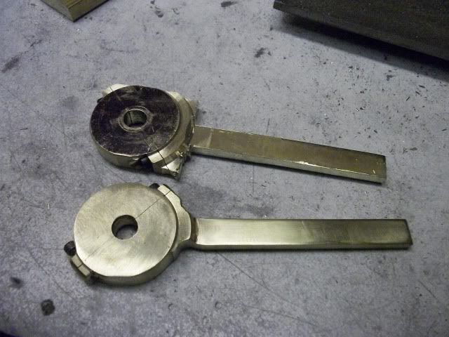
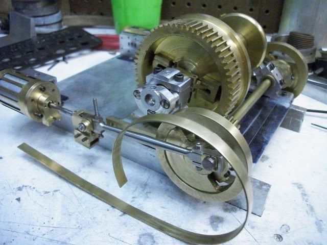
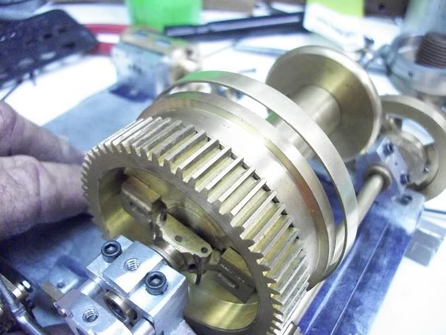
It is really difficult getting organized to proceed with this. I keep getting distracted with non-important jobs, like the fire door. I finally realized that the reason for procrastination was that there were so many unsatisfactory parts that needed rebuilt that I was just avoiding them by fiddling around with other stuff. I needed a plan. Here it is. Since I am happy with the winch side of the project and mostly unhappy with the engine end of it, almost everything on the engine side of it will be remade.

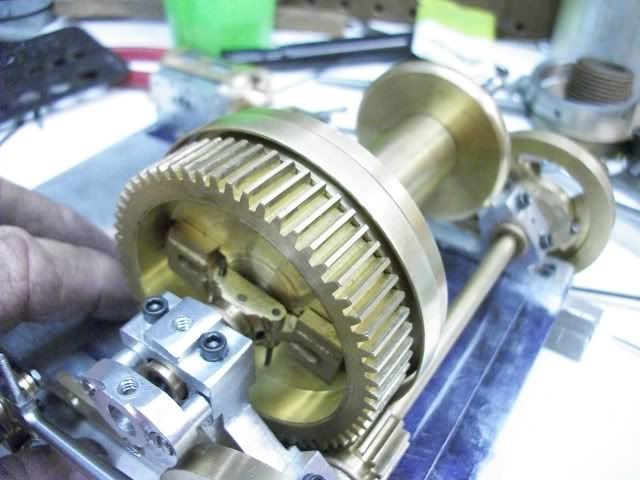
I had already remade the cylinders but I thought I would be able to salvage the heads and maybe the steam chests but that's just not going to happen. So it's most of it is being rebuilt. I have made some headway but have not been very careful with documentation because it is ground already covered.

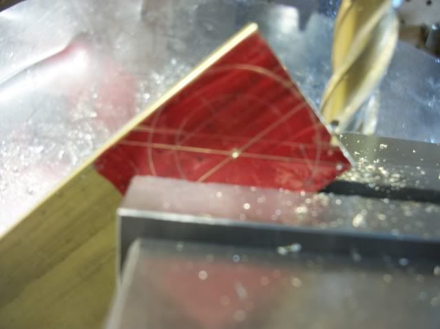
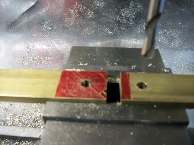
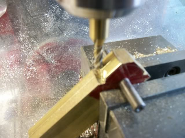
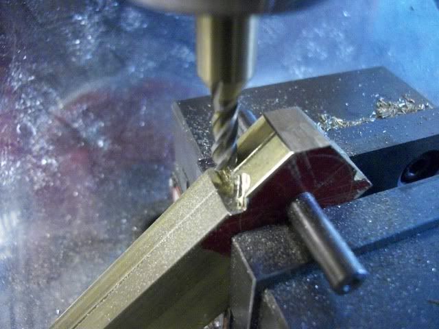
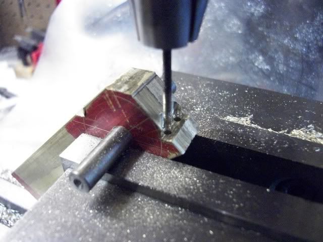
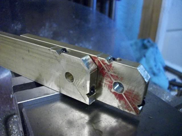
I will try to cover some of the things done differently such as the bolt pattern for the cylinder heads. I'm using 2-56 fasteners with a six bolt pattern. I will be using socket head cap screws for convenience during initial assembly and adjusting but will switch to hex head bolts or studs with nut where appropriate.

This is a first for me. No witness marks! Two cylinders, four heads, 24 drilled and tapped holes and they are all interchangeable! Any head fits either end of either cylinder and can be indexed to any position without worry. Every other cylinder that I have ever made was a nightmare of fitting, filing, marking and mahem. How did I do it? By eye.

I am being called for dinner and so I will post this now and continue with more after dinner.

Jerry
 
Jerry--- You and I seem to be approaching this from opposite ends. I am just in the final stages of engine building, and about to embark on the winch mechanisms. Its always interesting and informative to read your posts. ----Brian
 
Back from dinner. Eyeball positioning works like this. You put your eyeball on your DRO and use it carefully. There is no other way. Careful layout, marking and center punching has failed as has the use of a rotab. Maybe poor technique contributed to the bad results but I have finally achieved the results using inexpensive Grizzly/Igaging DROs at a cost of less than $50 and a second hand Last Word DTI.

Even the best DRO is only as good as its starting point and to me, the only valid starting point is the center of the bore. It takes a little care to set the cylinder vertical in the vise, with the valve face against the fixed jaw. Then you need to get it centered under the spindle. I can get repeatable position accuracy with .001" using the conical point of a center/edge finder but only if the bore is less that 3/8". Using the cylindrical end and a lot of repeated sampling against the inside edge, the best I can do is about .002" I'm not all that confident about that. Using the DTI against the inner face of the bore using the setup shown here, I can easily find the center within .0005" with a great deal of confidence.

backatit021.jpg


Then with the X,Y zeroed on center, the radius is cranked into the +X. I always use an even number for this to eliminate rounding error in a later step. In this case, the radius is .400". On the first cycle around the cylinder I am using a spotting drill. The second position is spotted at -.400". Four positions left. Crank in the +Y as R x cos(30°) = .3464 and if your cheap shop calculator doesn't have trig functions, cos(30°) = sqrt(.75) or just remember .8660. My DRO only only has three decimal display so I crank in Y = .346 and lock the Y. Then move the X to R/2 and since I am on the negative side of the scale the position is X = -.200 Spot #3. Then leaving the Y locked, move to X = +.200, Spot #4. Leaving the X locked move to Y=-.346, Spot #5. Then leaving Y locked, move to X=-200, Spot #6. Replace with the tap size drill and go around again and then replace with the tap and go around again. You only need simple calculations that you can probably do in your head. The radius, half of the radius, and the radius x .866 but don't do it in your head, use a calculator.

Drilling clearance holes in the heads follows the same positioning procedure except for the starting point. If it is possible to sweep the entire circumference the use the DTI as above but otherwise you will have to use the edge finder method. Be sure to center the Y axis first!

It took forever to write this and I had two glasses of wine with dinner, so If it's not clear, ask a question and I'll answer tomorrow.
23340
Jerry
 
Today I rebuilt the eccentric straps. I had previously made a one piece eccentric strap because I wasn't sure how to do this but when I built the overcrank engine, I made a two piece eccentric strap with a slant. Here is where it came from:

EccentricfromBrochure.jpg


That is a cut from the American Hoist brochure and I have wondered why it was made on a slant like this but there is very little room between the bearing hoist bearing stands and the crank web, where the eccentric lives, and access to the bottom bolt is made much easier by making it like this. What is not clear from the picture is that the eccentrics, which are integral with the crank web on this engine, are slightly recessed in the web so the eccentric strap has an offset to get in there. Also shown in the picture is the flat bar on the end of the bent valve rod that slides in a guide on the bearing stand like a crosshead guide. It adds a little interest to the mix.

My approach to split ecc straps is to lay it out, drill and tap for the bolts and then saw it in half (without the bolts). Then I put the bolts in and proceed with the shaping. Another nice benefit from the slant aspect is that I could get the parts out of a 1 inch wide bar and it would have to be a 1 1/4" bar if straight. Here are some pics of the process:

donkeyeccentric001.jpg


donkeyeccentric002.jpg


donkeyeccentric003.jpg


donkeyeccentric004.jpg


donkeyeccentric006.jpg


donkeyeccentric007.jpg


donkeyeccentric008.jpg


They just need a little more cosmetic milling and filing before boring the center for the eccentric.

Jerry
 
It's been a while for me Jerry but I sure did enjoy going through your thread again. The gear cutting, clutch mechanism (excellent!), trials and tribulations. It's a great thread.

A belated 'aye' from me.
 
Hi Zee, thanks for stopping by and leaving a message. The donkey and I are still growing. It may be as painful for the donkey as it is for me.

I am beginning to form a plan of attack on the brake band and it may work out with a little help. I was not sure how to form the strap without slip rolls but as it turns out hammer and anvil worked out just fine. Here are a few pics of the formed strap.

brakeband004.jpg


brakeband006.jpg


brakeband005.jpg


One end of the strap is to be fixed to the frame and the other end will be attached to a link and a foot pedal. The inside of the strap will be covered by some friction material that will contact the outer surface of the clutch/brake drum. I don't think I will have any problem with the linkage but I don't know what to use for friction material and how to attach it to the strap. I think it will be glued to the inside of the strap, probably with contact cement but I don't know what kind of material to use.

Help Please! Your suggestions will be much appreciated.

Jerry
 
This entire build is great, but that connecting rod and bearings are spectacular.
You gotta love that beautiful taper.

And that cylinder lagging is pretty slick too.
 
It's really coming along great Jerry Thm:

How about a strip of leather for the friction material ?

Kind regards, Arnold
 
The inside of the strap will be covered by some friction material that will contact the outer surface of the clutch/brake drum. I don't think I will have any problem with the linkage but I don't know what to use for friction material and how to attach it to the strap. I think it will be glued to the inside of the strap, probably with contact cement but I don't know what kind of material to use.

There should be no need for lining material on the brakes - metal on metal should be just fine - again, think chainsaw!
 
When I used to play around with IC off road models the centrifugal clutch bell was lined with a fibre type material which was about 1mm thick and quite flexible, just stuck a strip in with epoxy and it never shifted with all the heat and oil.

J
 
Jerry--give serious thought to a thin band of cast irom loctited to the outer diameter of the brass part that the brake band will rub against. That way the brake band can be made from a very large stainless steel pipe clamp. These are available without all the serrations for the tightening screw. A thin shell of cast iron can be liberated from a piece of cast iron pipe. Brass is simply too soft for any kind of brake and will gall.----Brian
 
Leather sounds like a good possibility, Arnold. It is one of the first things that I thought of but I don't know where to find it in the right thickness and texture. It needs to be thinner than belt leather. My wife has a pair of black leather gloves that she hasn't worn in thirty years. They are too long to be stylish today and a small strip from the cuff would hardly be missed. What do you think of my chances of getting away with it?

Tel, if the drum were made of steel, I would go with metal to metal, but the drum is brass and so is the strap. It would work from a functional point of view but I would hate to mess up the drum surface. As I am writing this, I am thinking that it isn't a high cycle, high load application so maybe I'll go naked.

Jason. Some kind of fibre material like you describe is exactly the right idea. Where did you get it?

Brian. The idea of a cast iron tire on the drum is good. It would solve the galling problem and I could still use the brass strap. If I was building this for heavy duty, I'm sure that is what I would do. If I come across an appropriate piece of CI, I will experiment with it.

Thanks for the input. All of the suggestions have merit. The hunt is still on. At least I can continue to develop the mechanism while I look for the material.

Jerry
 
May be easier to fit the lining material to the outside of the brass drum and then use a steel strap, spring steel is good but flat stock works OK, this is the band for my Traction engine about 6" dia

PICT0098.jpg


You could always use a wooden lining for the brake, plenty of traction engiens with that arrangement

J
 
If you don't want to try leather, Go to the local autoparts store and get some different gasket material. Some is asbestos and some cork. They should be fine for this application.
 
::) I forget about the big oceans in between... Locally here in Namibia they make shoes called "velskoene' and traditionally those have leather laces that are fairly thin strips of leather.

If you know of someone that restores old books, you might be able to get some thin leather from them. Some furniture and car seats also use thin leather, so a local upholsterer might be able to help you as well - just a couple of thoughts.

I don't think the texture will play that much of a role; but a suede-type might just have the edge.

I may be a bachelor, but I know enough about women and their fashions - the possibility that those gloves might come back into fashion at any moment in time might leave you in for the high jump ;D

Kind regards, Arnold
 
Sometimes you can get good leather from (discarded) handbags, purses, wallets, etc. I once used some of that to repair an diaphragm type air compressor.

Around here, some of the fabric shops have remainder bins where you can pick up pieces of different fabric and materials cheaply. I once "anti-rattle" lined the toolbox I kept in my car with upholstery vinyl for 25 cents US.

--ShopShoe
 
Jerry.

Please DO NOT cut up those leather gloves. *club*
I for one wish to see more builds from you in the future!! (And that means you being in one piece to be able to)!

I have found out to my cost, just the once, that it's better to NEVER to take a chance with womens things. :hDe: :fan:

Kind regards,

Ron.
 
Jerry---It doesn't have to be cast iron There is every size of thin-wall steel tubing known to man available out there. A peice loctited to the outside of your brake drum is the way to go.
 
Tel, if the drum were made of steel, I would go with metal to metal, but the drum is brass and so is the strap. It would work from a functional point of view but I would hate to mess up the drum surface. As I am writing this, I am thinking that it isn't a high cycle, high load application so maybe I'll go naked.

I can't see it being a problem. It does depend a bit on the prototype tho, dunnit! Does/did the original engine have liners?
 
OK. the gloves are off the table. My wife came in the bedroom and caught me feeling the fine texture of the leather and I guess I had a guilty look or something so she said "Aren't you a little old to be playing with Mommy's fine things?" I knew I would catch hell if I told her what I was really thinking so I just said "Opps! Busted" and slunk out of the room. This is a weird place that I live.

Tel

Here is a pic of the real animal. You can see some kind of material between the band and the drum surface. You can also see the bolt or rivet heads that secure the lining to the band. It looks to me, like ordinary asbestos brake lining.

D349-1.jpg


D3410-1.jpg


In the shop today, I tried the brass band against the brass drum. It doesn't take much pressure to stop the drum but it showed another reason that lining is needed. Noise. The very slight metal to metal contact when the brake is disengaged makes the band sing like a bell. Very annoying. A little sound damping would be a good thing.

There are a couple of other details worth mentioning. It has been suggested that the ratchet and pawls are not needed on this type of hoist but you can clearly see the wear on the teeth,more obvious on the front drum, indicating heavy use and abuse of this feature.

From this point of view, you can see the small pockets in the drum flange, close to the drum core and arrayed radially around the drum. These pockets are to mount the wooden lagging staves to increase the dr.um diameter and line speed on lightly loaded applications.

Thanks for watching.

Jerry


Latest posts

Back
Top