Building a Bonzer Bonzer

Home Model Engine Machinist Forum

Help Support Home Model Engine Machinist Forum:

This site may earn a commission from merchant affiliate links, including eBay, Amazon, and others.
Thanks Jim.

The valve cage assemblies are completely machined and will be "tweaked" once they're installed in the cylinder head. Stainless (303) valves, bronze valve cages, brass spring retainer and jam nut. Two required, and one spare. The springs I've used presently are what I had on hand.


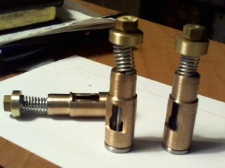
I'll use the Rupnow method of adjusting spring tension by rotating the engine and watching intake valve movement. That's still in the future.

The next step will be to machine the ports in the cylinder head.

Thanks for looking in. Comments always appreciated

Cheers,
Phil
 
Philjoe--You are doing nice work. I never cut the openings in the sides of the valve cages like you have done. Why?---Because I always use some green Loctite to assemble the valve cages and the cylinder head. After it has dried overnight, I cut the hole in the cylinder head and the valve cage at the same time. To do it any other way and use Loctite, you will end up with the inside of your valve guides full of Loctite when you assemble things.
 
Hi Brian,
I thought of doing the machining the way you described for the reason you stated. But, in the past I've had good results with a smudge of loctite, then after it sets, a quick wipe with a bronze or nylon brush soaked with acetone to get it out of places I don't want it.

The reason I cut the port first is so that I can work on the cylinder head independently of the valve cage. If I screw it up, and I have proved I'm capable of doing that, I can punch out a new cylinder head in an hour.

The valve cages took me a lot longer to make. Plus, if one of the cages or valves gets worn, I can just press out the old, press in the new.

BTW Brian, thanks for the tip of doing the guides first, followed by the valves. Getting the valve stems to nearly the correct diameter, then finishing the job with a file worked fine for me.

I forgot to include a picture of the component parts so here they are:


The adventure continues.

Cheers,
Phil
 
Hi Phil, I did it Brian's way as you know but I will be interested to see how your way works out.

When I built the other engine using valve cages, I drilled and tapped the ports in the head before installing the cages and then used a threaded guide to set up the head for drilling the cages. So I think I could replace the cages and drill through again.

As long as the skin is removed from the cat ...

Jim
 
Jim,

I drilled and tapped the ports in the head before installing the cages and then used a threaded guide to set up the head for drilling the cages
That's a good tip and one I hadn't thought of. Well I guess if I loctite my valve in its guide you and Brian have given me some alternatives. I'll post my results here, of course, but if something bad happens go here:

http://www.wgal.com/weather/sky-cams

and you will see quite an amazing blue cloud of obscenities that will have local meteorologists scratching their heads for years to come:D

Cheers,
Phil
 
Nah ... nothing will go wrong! What could possibly go wrong?

The skycam will show nothing but blue skies with silver linings.

Jim
 
Not a lot of work in the shop today. But I did make a fixture plate to hold the cylinder head for its machining operations.

I through reamed two 5/16" holes for the cages, then drilled those holes out to 3/8" diameter to a depth of 0.645" to fit the profile of the cages.

Then I drilled the connection to the spark plug hole 3/8" diameter to a depth of 0.60".

My 3/8" holes compare to the plans 9 mm (0.354"). I had laid out a scrap piece of ally to make sure these holes wouldn't intersect. This may seem like a lot of effort, when pencil and paper or a drawing program would have settled this. But doing this beforehand allowed me to determine what diameters to turn the guides to for a press fit. I used the same cutting tools for the trial and the final work.

I wanted flat bottomed holes, easily gotten with an end mill, but end mills often cut oversize holes. So I used a 3/8" carbide end mill, which made a hole like a reamer, uniform and true to size as measured with a dowel pin, a close fit at 0.375".


Time to get out the metric tap for tapping 10 mm x 1 mm threads for the ports.

Note the black ink marks on the work to keep me honest. The "S" is where the spark plug goes.

Cheers,
Phil
 
The head is always the tricky part but you seem to have it well under control.

Jim
 
The side plug design is pretty slick Jim, and not so tricky.

I decided to machine the intake/exhaust ports without using a fixture, so I set them up in the milling vise in my usual fashion


Then I found the edge of the work. With the right tools that was as easy as 1-2-3 :)hDe:)


I drilled all the ports using a "T" drill for the pilot and tapped them all 10 x 1 mm. I think I did OK because I've got 3 holes on this side


and only 2 holes on this side, which seems right


And here's the finished product:


Honestly, this was way less problematic than when I first saw it in the plans. Of course, this design hasn't been tested out but others have used the side plug with good results so I'm not worried (too much).

Now I only need to loctite the guides in place, and the head is finished.

I'm looking down the road a bit and thinking of using CI spoked flywheels for this engine. I've got two choices in mind. I've had good success with machining these in the past:


The larger one is 7" diameter, weighs 4 lbs, the smaller one is under 6" and weighs 2 lbs. Is bigger better?

Thanks for looking in.

Cheers,
Phil
 
With a bit of coaxing, the valve cages were pushed into position and held with a drop of loctite. After an hour I swabbed all inner surfaces with MEK to remove any excess.

The valves were installed, shown here:


and the cylinder head was installed on the cylinder


With a piece of tape over the spark plug hole there is definite compression when I turn the engine over so I think my valves are seating OK.

I'm out of the shop while I ponder my next move. I think I'd like to tackle the cam and exhaust valve linkage so I'll study the plans over the next few days. Maybe some research on flywheel weights while I'm at it.

All comments appreciated and thanks for looking

Cheers,
Phil
 
That head looks great! So good in fact, that I am tempted to make one myself (when I get enough time).

Jim
 
Philjoe--You are doing nice work. I read your posts every time you put something up, and you are progressing very well. It's exciting, isn't it.---Brian
 
Thanks Jim and Brian. It is exciting to be making parts for the first time that really test the limits of my ability. I'm encouraged that I have some compression at this point and I still haven't made the piston rings.

I bought a 10 x 1 mm bolt that I can screw into the spark plug hole to test my valve seals. A spark plug is on its way, but I haven't thought much about the ignition system, other than I think I want a points, coil, condenser, battery system.

I really thought I'd be fighting the valves and cylinder head work for a much longer period of time. Which probably means something I think should be simple will take much longer to finish. I remember going into the shop one morning to make a simple bushing. Hours later, after 3 tries I finally made one that would work, but I honestly knew it was pretty sloppy. So next day, with a fresh perspective I made number 4, which I was happy with.

I still am undecided about my next step...valve gear, flywheel, piston rings? I'll pick something fun!

Cheers,
Phil
 
Just to prove I'm serious about building this engine I went out and bought a spark plug for it


It's kind of looking like an engine.

Others that have made IC engines comment that compression is essential for a good runner. So, I'm going after the valve gear followed by the piston rings. No point in making flywheels or a governor if I can't get compression, right?

Meanwhile I'm playing with a new toy...an ER-40 collet chuck for my 10 x 22 lathe, which I'll give a full report on in the "Tools" forum soon.

Cheers,
Phil
 
Last edited:
[FONT=&quot]I was having a little trouble seeing how I’d make the cam until I realized that the basic idea is to start by cutting 2 diameters on a piece of stock. Then just cut away anything that isn’t a cam.[/FONT]

[FONT=&quot]I made the basic 2 diameter workpiece from some 1144 alloy steel. Then I drilled it and bored it to fit the hub on the 60T gear.[/FONT]

[FONT=&quot]
[/FONT]


[FONT=&quot]I made a fixture to hold the work and set it in the mill vise at a 40 degree angle and milled the major diameter down to the minor diameter. Flipped it over and did the other side.[/FONT]

[FONT=&quot]
[/FONT]


[FONT=&quot]With the work still on the fixture I milled off most of the excess. I color coded the work so I wouldn’t add to the scrap bin, blue = keep this, red = remove this[/FONT]

[FONT=&quot]
[/FONT]


[FONT=&quot]I finished rounding the cam on the rotary table.[/FONT]

[FONT=&quot]
[/FONT]


[FONT=&quot]Finally, I tapped two holes 8-32 for grub screws. Here is the cam with its 60T gear. Ironically, the last part made alongside the first part made for this engine.[/FONT]

[FONT=&quot]
[/FONT]


[FONT=&quot]Thanks for looking in[/FONT]

[FONT=&quot]Cheers,[/FONT]
[FONT=&quot]Phil[/FONT]
 
Hi Phil,

That is really good explained how too build a cam.
Thanks for that. I like those tips.

barry
 
Thanks Barry. I started digging around to find where I had the "two diameter" idea and it was from our very own Cogsy, posted here:

http://www.homemodelenginemachinist.com/f26/cam-making-basics-21145/

If you look on the right hand side of my last photo, you can see part of an image of a cam with the red part to be removed. This is a real mind bender because when I color coded my cam prior to milling I must have had a subliminal thought that went back to that post by Cogsy. Anyway, I officially pass the kudos to Cogsy

Cheers,
Phil
 
Work on the valve gear continues. My immediate goal is to get the cam - push rod - rocker arm connection complete and see how my valve operates as I turn over the engine. Seems like building an engine of this type is a series of short term goals that will eventually all add up to a running engine.

Making the push rod assembly was straightforward and only presented me with one item outside my comfort zone. One end of the assembly is a connector with a 4 mm slot (0.157"). The easiest way to make this would be to use a 5/32" end mill, which I don't have. I'm sure there is some good reason why single end mills in the US are usually sized by 1/16's while double end mills are sized in 1/32's???

Anyway, I do have a slitting saw that's 0.051" thick and 3 x 0.051" = 0.153"!


I tested the slot width after 3 passes of the saw by using a #22 drill (0.157") and it fit the slot.

Making the rest of the pushrod went smoothly.


The rocker arm and its mounting bracket are next while I await delivery of some 16 and 14 gauge steel for the cam follower and bracket.

Thanks for looking in

Cheers,
Phil
 
Some days you go into the shop planning to make a part that requires quite a few operations. At step #2 in a sequence of about 20 steps you mess up. Then you decide to either give it up for the day or make something simple.

Like the exhaust pipe


Make sure it fits because it's been that kind of day


Oops! attached here to the wrong port! OK, I had a pretty good day after all, I can fix this:p

Cheers,
Phil
 
Last edited:
Some days you are the dog, some days you are the lamp post. Looks like today was a dog day for you.

Jim
 
Back
Top