Building a Bonzer Bonzer

Home Model Engine Machinist Forum

Help Support Home Model Engine Machinist Forum:

This site may earn a commission from merchant affiliate links, including eBay, Amazon, and others.
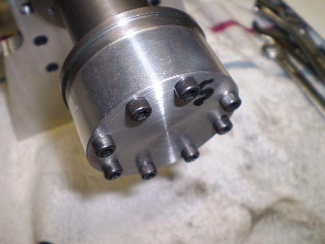
I started the cylinder and am working slowly since there seems to be a lots of places where I can ruin it. I decided to use the rotary table to drill the eight #8 mounting holes. In order to attach the work to the table, I turned the work to 3 diameters. The smallest is a 25 mm register that fits in the rotab. The middle diameter is a register of 30 mm that fits in the cylinder and the largest diameter is the head itself. Finally, the small end was tapped 3/8 -16 so I could bolt the work to the table. Shown here with the holes drilled


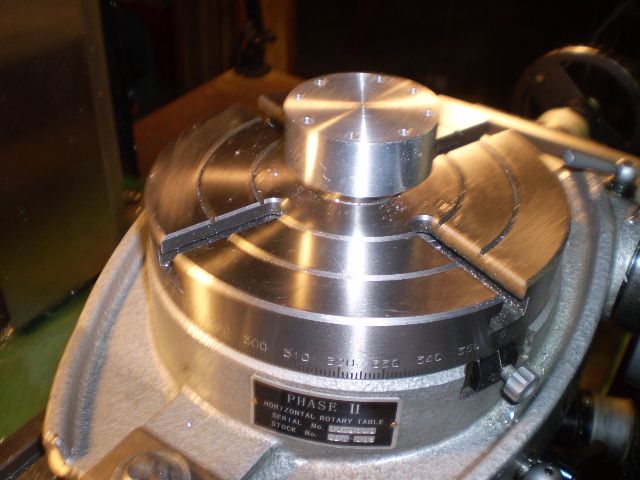
I must admit drilling holes on a bolt circle is pretty easy once you figure out how to attach the work to the table.

Then, convincing myself that no further machining was required on the rotab I removed the head, parted off most of the small end and faced it to length. Then I checked it for fit on the cylinder.


Before I machine the cylinder head further I'm going to make a trial valve and cage assembly. Then I'll tap the head to hold them.

I'll be a while because I'm winging it with dimensions

Cheers,
Phil
 
I spent last week preparing for Rough & Tumble's Fall Harvest show. I met fellow HMEMer's Tin Falcon, cheepo45 and many other friends there including my friend Earl who took a photograph of an old steam engine, made castings and then built a working model!! Sadly, this picture does not do his model justice but it was the only one I had:


Meanwhile, I spent time studying the valve and trying to decide how to approach making them.

The valve stem has 3 grooves for e-clips to hold the spring retainer. Three rings allow coarse adjustment of spring tension. I decided to thread the end of the valve stem 4-40, thread the retainer 4-40, and that will allow me to screw the retainer on for fine tuning spring tension.

First step was to take some 3/8" cold rolled, and turn a length of about 1/4" to 0.112", then thread the end 4-40 using a tailstock die holder.
Next I made a fixture that's tapped 4-40 and is chucked in my rotating tailstock drill chuck live center.


Next, I turned the appropriate length to 0.125" to fit the valve guide. Then, I cut the valve seat using a D6 carbide brazed toolbit with a 45 degree angle. I made this cut at very slow speed, lots of cutting oil and finally parted off the valve shown here. The stem has a rough finish but the valves I intend to use will be made with more attention to finish.


This was a practice run to see how my setups would work and I'm satisfied they'll make a working set of valves. So I'm off to the shop to make a pair of valves out of some 3/8" stainless (303) I have. This will take some time since I'll also make the valve guides and I want to cut the seats on the guides and valves at the same time with the same machine settings.

Cheers,
Phil
 
It was good talking to you too cheepo45. I enjoyed hearing about your IC (Upshur) engine build and watching it run was a good motivator to keep me going.

Cheers,
Phil
 
I'm still fooling around with valve cage designs using paper and pencil. I'm getting closer to the final details. Meanwhile, just to cut something, I made these jam nuts threaded 4-40, for the valve stems (0.125" diameter).


This is near the limit of my ham fisted ability to handle stuff. Luckily, there are not too many parts on this engine of this scale.

Cheers,
Phil
 
Thanks Jim. Unfortunately, that was yesterday. Today I've managed to make a few contributions to the bronze recycling bin:Doh:. But, I did learn a few things along the way so all is not for naught (always wanted to use that word).

Cheers,
Phil
 
If you haven't made the valves yet Phil, you may want to consider a trick I recently learned from Brian Rupnow and leave the valve attached to a decent (1"+) piece of it's stock material. That gives you a nice, convenient piece to grip when you're lapping the valves. Once the lapping is done to your satisfaction you simply chuck the valve back into the lathe and part it to it's correct length. It's a heck of a lot easier than trying to use the tiny 1/8" stem to lap with.

I don't think I've commented on your build yet, but I'm following along and I have to say it's looking great.
 
Thanks for that tip for valve lapping Cogsy, and you too Brian if you're looking in. I missed that one. Seems to be a wealth of information around on HMEM.

Cheers,
Phil
 
Phil--I am watching. You are doing a fine job.--The whole valve building process was covered in my build of the "Rupnow Engine".---Brian
 
Thanks Brian. I do believe I'm going to make a pot of coffee and go through your build and others making your H&M and try to educate myself. I know I'll find nuggets. I couldn't have gotten this far without help from fellow HMEMer's and my friends at Kinzers Rough & Tumble.

Cheers,
Phil
 
I have a design for the valve cage that should work OK and will be easy to fit to the cylinder head.


There is a small thin flange on top that will rest on the cylinder head. I milled a notch midway that will align with either the fuel intake port or the exhaust port. The example shown here with valve inserted was made from brass, but the final product will be made of bronze. I'm planning to make a pair plus spares.

Cheers,
Phil
 
Hmmm ... interesting approach. If I understand correctly, you plan to insert the valve cage from the outside of the head. I pushed mine (on a different engine) from the inside to be sure that it fitted flush.

And you have cut a notch for the ports before inserting where I waited for the Loctite to set and then drilled through from the holes I already had in the head to break through the cages.

It must be the different hemispheres that cause we antipodeans to do things upside down. Possibly it is related to the direction in which the bath water goes down the plughole.

Jim
 
Hi Jim,
Possibly it is related to the direction in which the bath water goes down the plughole.
And you guys drive on the left side of the road:confused:

Well you did interpret my approach correctly. I'm wondering about your comment:

I pushed mine (on a different engine) from the inside to be sure that it fitted flush.
So I gather your valve cage didn't have a flange of any sort and just went straight into the head, is that right? And, is there a problem if the valve or cage were a few thou proud of the cylinder head on the inside?

I think this will be the only part of the engine where I'm off plans so I appreciate the feedback.

Cheers,
Phil
 
Brian,
Actually I think I went through a pot of coffee, a few brewskis, and an oz of Irish Mist, but I did get through most of your 50+ pages of build. I think you flew through all that while I was figuring out how to make gears. Anyway, thanks for posting all that detail because it IS appreciated and is a great source of ideas.

The valve and guide stuff is good food for thought, especially the lapping part.

Perhaps If my Bonzer is a runner, I'll tackle your IC engine.

Cheers,
Phil
 
Hi Jim,

I think this will be the only part of the engine where I'm off plans so I appreciate the feedback.

Cheers,
Phil

Horror of horrors! Your comment made me go and check the plans.

I thought there was a side plug head with valve cages in the Bonzer set but I had confused it with the Rino engine that I am (slowly) building at present. Rino does have a side plug head with cages but this is an improvement on Bonzer.

How embarrassing :wall:

Jim

Drawing of a modified head and a suggested valve cage were emailed to you this morning (with apologies for the omission).
 
Last edited:
Jim, Brian,
After looking at your plans I decided it may be best to put the cages in from the combustion side of the cylinder head. The combustion pressure will want to push the guides out of the head, so your design would prevent that from happening, mine wouldn't.

I'm getting closer to completing this assembly of parts. Having spent a month learning all about spur gears I'm not at all discouraged at my progress with this part of the build. I knew it would be trickyscratch.gif

Cheers,
Phil
 
I've been busy with the Bonzer but progress has been SLOW! I started this project thinking there were 3 areas that required the best work I could accomplish: gears, valves and guides and piston rings. So I'm really taking my time with the guides and valves. This is WIP report for those items.

I decided to make 3 of these assemblies, two are required and 1 spare. Here are the bronze guides, needing a bit of filing but otherwise serviceable.


After playing a bit with valve design and dimensions I've gotten through the better part of 2 valves. Shown here before cutting the seat and trimming to length.


The completed valve shown was a practice piece using cold rolled steel. The actual valves are stainless (303). This work goes fairly slowly but I'm getting what I "Think" will be serviceable valves. Time will tell. One thing's for sure, I'm learning a lot and folks here have kept me on track.

I'm starting to have visions of a completed cylinder head dancing in my head:)

Thanks for looking in

Cheers,
Phil
 
Back
Top