Back to Steam

Home Model Engine Machinist Forum

Help Support Home Model Engine Machinist Forum:

This site may earn a commission from merchant affiliate links, including eBay, Amazon, and others.
Charles--I'm not overly concerned what the pieces are called. There may have been a time when steam ruled the world, but that is long gone by. I am undertaking this exercise just to "see if I can". For my money those two links are the parts that are most critical in making the engine run in reverse, ergo "reversing links" works fine for me.
 
This is a very well done assembly video of the engine I am building. The reverse mechanism has a few minor differences, but the video is amazingly well done.
[ame]https://www.youtube.com/watch?v=M9r7gw-XxIc[/ame]
 
Okay, it's time to ask for an opinion. I am going to require a total of four eccentric strap assemblies. Two with straight rods connecting the ends and two on which the rods have a 1/4" offset. In the normal course of affairs, I would thread everything and screw all the pieces together. Although they look huge in this picture, they are only 1.646" center to center. I have a fixture to mount everything on at the exact centers required, and it is imperative that all four center to center distances are exactly the same. I'm thinking to myself "Why not set them up one at a time in the fixture and silver solder the rods to both ends?" The only adjustable thread required would be on the rod which passes thru the valve nut, to center the valve for timing the engine correctly, and the rotational position of the eccentrics on the crankshaft. Opinions please.---Brian
2pADRU.jpg
 
I'm thinking to myself "Why not set them up one at a time in the fixture and silver solder the rods to both ends?" The only adjustable thread required would be on the rod which passes thru the valve nut, to center the valve for timing the engine correctly, and the rotational position of the eccentrics on the crankshaft. Opinions please.---Brian

Use jig to keep fixed length of rod before silver soldering the rod to both ends. Then the rod for valve must be adjustable for correct timing.

See my Stuart D10 in avatar, there are not threads on the rod to ends.
 
Brian,

When you start a project, you really get it done. I don't know if you're obsessive or nuts?!?! :)
 
Brian,

When you start a project, you really get it done. I don't know if you're obsessive or nuts?!?! :)

Probably a bit of both. When I have unfinished anything it eats at my soul until I get it finished. :eek::eek: I admire the guys who can leave projects unfinished for weeks at a time and not have it bother them.
 
Brian,

You have solved a problem for me. I have been visualizing several projects that need control levers and every one would need a smooth handgrip and making more than one so that they all matched would probably not turn out well for me.

Your knurled handle solves that as I can make cylinders more easily than "handgrip-shaped" handles.

Filed for Future Reference

I am enjoying this build, just like all your projects.

Thank You,

--ShopShoe
 
The only problem with jigging them individually might be a slight variation due to expansion and contraction when soldering. There might not be enough to worry about but you may want to jig them in pairs.
 
Glad I was able to help, Shopshoe. Those little bits of knurled brass Loctited to the shank of a handle give it a little class. and you don't have to have any fancy prep work on the end of the handle either. Just knock any corners off on the belt sander so it will fit into the hole drilled in the brass bit.:eek::eek:
I am getting to the point where all the major links and levers for the reversing system are finished. I have a few itsy bitsy pieces to make and then I'm ready to try this reverse business out. All of the blue parts in the model are finished.
H5LHIy.jpg

nRl4cI.jpg
 
I've just had one of those days where it seems I worked awfully hard for minimal results. Most days I go like a whirling dervish and at the end of the day I have a collection of parts to show what I've been doing. Today I made three parts and figured out how to make the final three. I really hope this reversing mechanism works. It is very interesting and there seems to be a lot of small parts involved. I should know in the next two or three days.
 
The only problem with jigging them individually might be a slight variation due to expansion and contraction when soldering. There might not be enough to worry about but you may want to jig them in pairs.

TonyM

No problem, i did with the rods and ends: Solder the big end first then let it cool down and solder the last small end.
 
This quest for a reversing engine is taking me in some strange directions. I finally have all of the pieces made, tomorrow I will silver solder up the eccentric strap sub assemblies. In the picture you will see a couple of 1/8" shafts with hex nuts soldered to the ends of them. They are destined to be sawn in half and then threaded on the cut ends to yield four hex bolts.
umUNXD.jpg
 
I have the first eccentric sub assembly fixtured and ready for silver soldering in the morning. I drilled the center out of the 5/8" fixture rod, leaving only a 1/32" wall so that it doesn't act as a big heat sink. There is a very slight air gap between the eccentric strap and the aluminum fixture plate, probably only about .005", but that will stop a lot of heat from being sucked out of the brass strap end as I solder it. The 1/8" pin which locates the small brass end can be pressed out from the far side if I need to in order to remove the sub assembly from the fixture. I have to do two sub assemblies like this and two with a .25" offset bent into the 1/8" rod. I'll let you know how I made out in the morning.
UfiBas.jpg
 
I'm very pleased with how the silver soldering went on my four eccentric strap sub assemblies. I got good flow all around the 1/8" rod at both ends, and good fusion between the steel rods and the brass ends. My "soldering fixture" worked like a charm. I have set one of the assemblies with an offset end up in the fixture for one shot, so you can see the spacer underneath the large end of the strap. I had no problem removing them from the fixture. A two hour soak in Citric acid and then some brisk scrubbing with my small brass bristled brush yields some very nice looking parts---and they are all exactly the same center to center distance.
ODovD1.jpg

jPn8jY.jpg
 
Up until this point, I have been reasonably sure of what I was doing---as in "Okay, I've done all of this stuff before, so I'm not covering new ground here." Now I have arrived at something totally new, the timing of the two cams at each side of the engine, in relationship to each other. The solid model I have shows a separation of 120 degrees between the high point of the lobes on the two adjacent cams. The part which I have been referring to as the "reversing plate" has a total included angle of about 30 degrees. I have absolutely no idea as to whether this is correct or not. Whoever has created the 3D model I have worked from has done a sensational job, and I can proceed based on blind trust that he has modelled this relationship correctly, but I would really like to have a better understanding of how or why this works. If anyone out there can shed some light on this, I would really appreciate it.---Brian
AW6Yxp.jpg
 
Actually, I know how keen you are to get on, so we can do a sanity check quickly.

Take the overal distance between the outside edges of the ports, and the overal length of the valve. Half the difference between these dimensions is the 'lap', ie the amount the valve in mid position overlaps the port edge at each end.

Now draw a circle with a diameter equal to the total valve travel given by the eccentric. Draw a horzontal line positioned below the centre of the circle by the amount of lap. Draw a radius each side to the intersection of the circle and the line (to form a chevron). The angle between the radii is the angle between your eccentrics. Bob's your uncle.

The designer may well have reduced the angle a smidgen to provide a bit of 'lead' or advance opening of the valve a few degrees before top dead.
 
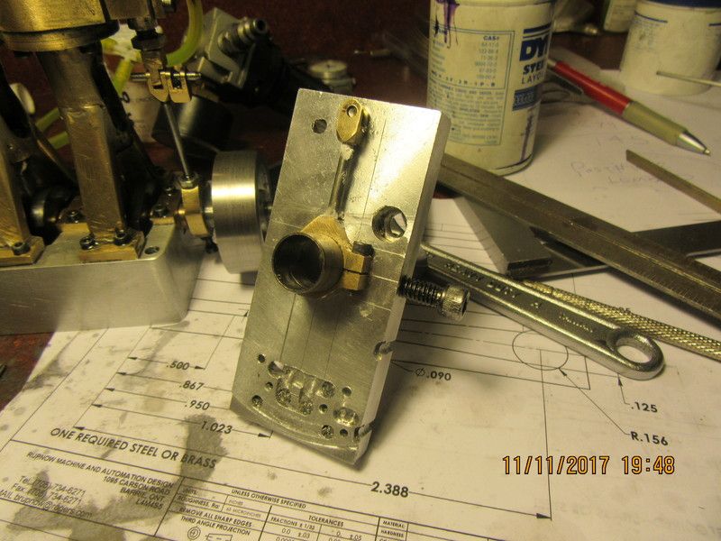
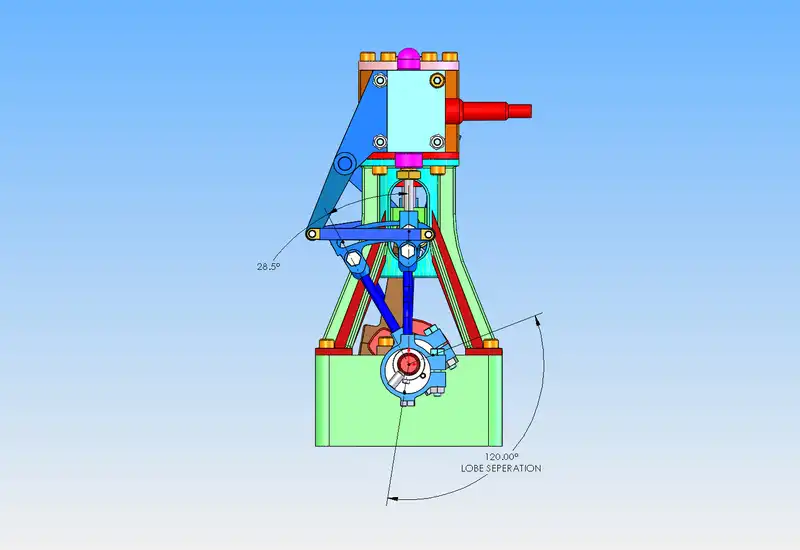
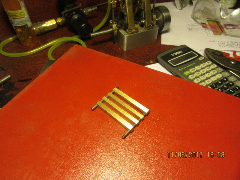
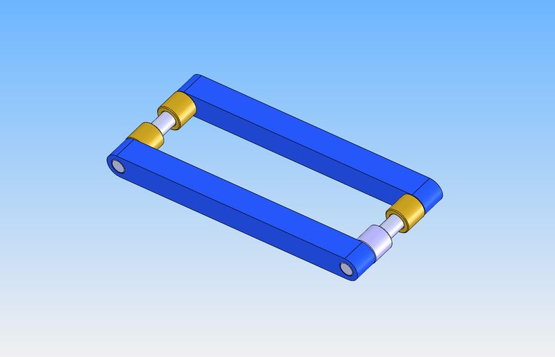
Thank you gentlemen-My knowledge of steam engine valve setting so far, extends to the eccentric position relative to the crankshaft and the slide valve relative to it's position in the steamchest. The "throw" of the eccentric should be equal to 1/4 of the "throw" on the crankshaft. My crankshaft has a "throw" of 3/8" (which gives a total stroke of 3/4"). The "throw" on my eccentric is .094" which gives the slide valve a total travel of .188" . When the piston is at bottom dead center, the eccentric lobe should be half way thru it's highest and lowest points of travel (that is how you position the eccentric rotationally in respect to the crankshaft. Also, at this time and position, the slide valve should be exactly half way thru it's full travel (3/16") in the steamchest. This method has always worked well for me. The set up for reversing apparently follows exactly the same procedure when setting up with the straight rod directly below the valve rod vertically. When the reversing handle is rotated thru 30 degrees, this brings the offset rod into position directly below the valve rod and hopefully makes the engine run in reverse. I think I've got it, but will only know when I have everything reassembled. I'm a bit unclear what happens at the other cylinder, as the crankshaft is 90 degrees "out of phase" yet is still connected to the same reversing lever.
 

Latest posts

Back
Top