Back to Steam

Home Model Engine Machinist Forum

Help Support Home Model Engine Machinist Forum:

This site may earn a commission from merchant affiliate links, including eBay, Amazon, and others.

Brian Rupnow

Design Engineer
Project of the Month Winner
Joined
May 23, 2008
Messages
14,975
Reaction score
8,266
Location
Barrie, Ontario, Canada
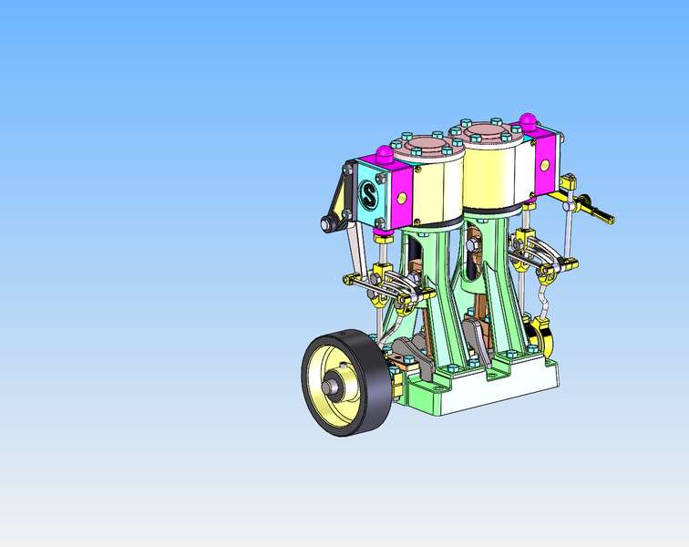
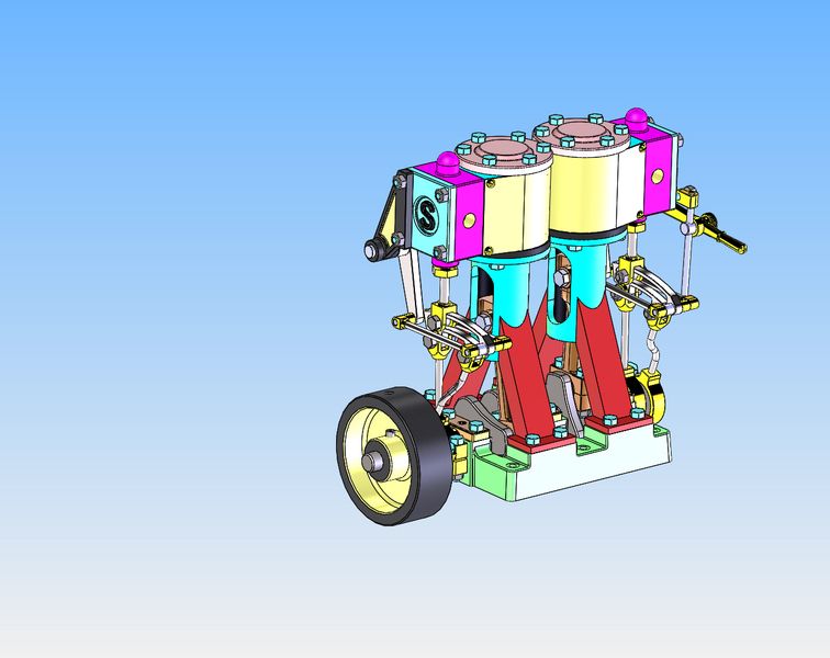
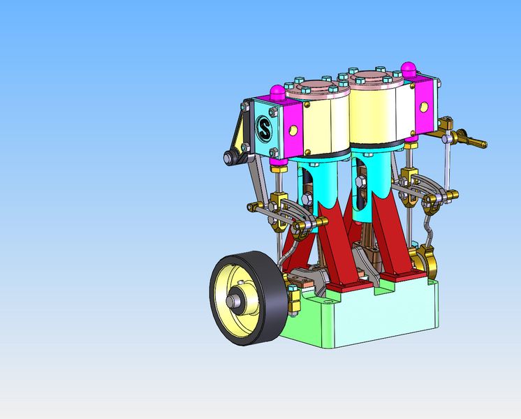
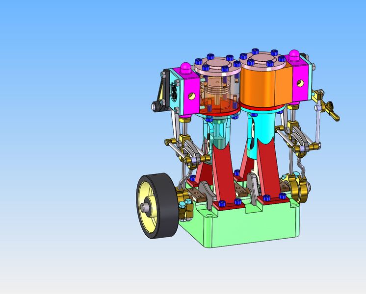
I have always been intrigued by the Stephensons Link reversing mechanism that was used on some steam engines. While searching for information about it, I was directed to "GrabCad", a site where 3D models can be downloaded free of charge. There is a complete and very detailed model of a small two cylinder steam engine, 3/4" bore x 3/4" stroke, with the reversing mechanism on it. It is quite a lovely model, and it is obvious that many of the major components are castings. This afternoon I have been playing on my CAD system to see what would be involved in making this engine from bar stock. This is what the engine looks like as downloaded.
yOkfvv.jpg
 
The most complex casting is that of the cross-head and the two supporting legs which hold it in position. If I was a real fanatic about it, I might be able to carve this from one lump of metal, but it would be a very trying exercise---and there are two of them.
NHEOGR.jpg
 
It appears to me that this could be fabricated from three pieces of either steel or brass, silver soldered together. It wouldn't be nearly as pretty as the casting, but should function the same, and be much, much easier to fabricate. The round portion is pretty straightforward lathe work, and the legs could be fabricated from either one or two separate pieces. It might be tricky to turn the radius in the leg where it has to match the outside diameter of the round cross head, but that is simply a matter of fixturing.
OGvtH5.jpg

gJwMVK.jpg
 
Could you not simplify the shape. If you have Mill and lathe, you could face off a chunk of steel. Bore the centre out. Make a mandril to rechuck it the other way around. Then turn a step for the bolted feet, marking PCD for bolt holes, taper the bottom half to a cone shape then a circular shape for the top. Mount in a Mill and get rid of the excess material, to size the stands the same width as the guide. Mill out the guide hole and you have a rough shape of what your after. I don't know the engines and haven't seen the drawings so not sure if there would be any interference with the valve gear doing it this way??? It is a little wasteful on material though!!!
 
As I said, I could probably hog the whole thing out of one piece of metal, but it would be a lot more work.
 
Looks like an interesting project Brian. I always have a lot more success with steam than IC engines.
 
This is going to get interesting. Although the solid models have been designed in inches, it appears that in some places the numbers used may be direct conversion from metric. Also, the bolts used are 7BA and 8BA, which I am not familiar with. I will be converting the fasteners to Imperial sizes, mostly #5-40 and #4-40.:eek:
 
The base casting for this engine is only 5/8" deep, and as a consequence, both the flywheel and the crankshaft extend below the bottom of the base. This makes it necessary to use a built up sub base with the engine as designed, to give clearance for the crankshaft and flywheel to rotate. I have kept all of the features of the upper surface, but extended the "skirt" another 1/2" so no sub base is required. The original base casting had sloping sides, partly for ease in casting the part and partly for "aesthetics". I have opted to make the sides vertical for ease of machining. This will have no impact on how the engine functions.
rGoH1a.jpg
 
The only other radical departure from the "casting style" is the connecting rod. On the left you can see the original "as cast" connecting rod and rod cap. On the right is the same con rod and cap machined from solid. Now remember, I have shown the "machined" con rod with no radius on any of the sharp corners. If you wanted to, for "aesthetics", you could file in any number of nice radii on the machined rod, but other than for "pretty" they aren't really needed.
okcFX7.jpg
 
MarkT--That is certainly a beautiful and great running engine that you built. Considerably bigger than the 3/4" bore x 3/4" stroke on the engine I am working on.---Brian
 
There was one more change. The original cylinders had sheet metal lagging around them (and probably insulation between the cylinder body and the lagging.) Since I will be running this engine on compressed air instead of steam, it is much easier for me to do away with the sheet metal lagging and make the outer body of the cylinders the same shape as the lagging used to be. I have also changed out the original bolts and nuts to all #5-40 socket head capscrews. I know this last step with the bolts will have many of the purists squealing in agony, but I like the socket head capscrews much better.
Wup4G3.jpg
 
So--To build this, I can use brass, steel, or a combination of brass and steel. The round center portion can be either material with no penalties. The legs are going to be nasty to cut the half round in where they mate to the cylinder. Since brass is so much easier to machine than steel, I see the legs as definitely made from brass. The feet can be either metal, again with no penalties. I have all of the material in stock to make it this way. I'll have to think a bit about the round part--I have the material for it in steel but not in brass.
kifmYH.jpg
 
Hi Brian,i too built the Stuart 10v single cylinder frrom castings
The one you are looking at is the D10 twin version with reversing
gear as optional extras.I too looked at then making the twin
from bar stock as you but got no further It is a nice little engine
 
Brian,

I like your design and I am confident that you will meet the machining challenges. I am like you in that I really don't like to machine steel as well as I like machining aluminum and brass, but I think you will get this done.

I'm looking forward to seeing the chips fly on this one.

--ShopShoe
 
Okay--how are we going to do this?---Maybe--Start with a piece of 1/2" flatbar, with the overall height and width and thickness machined to match the outside of the legs.
wUyuNe.jpg
 
Back
Top