Back to Steam

Home Model Engine Machinist Forum

Help Support Home Model Engine Machinist Forum:

This site may earn a commission from merchant affiliate links, including eBay, Amazon, and others.
There's a guy on youtube : Keith Appleton , and he has several videos
explaining in detail how to set the timing .

Keep up the good work , lovely as always .

Pat
 
Here is a short video of me practicing my Canadian Newfie accent and demonstrating the working of my first stage of reversing mechanism.
[ame]https://www.youtube.com/watch?v=d2UiP4gDUKE[/ame]
 
Thank you gentlemen-My knowledge of steam engine valve setting so far, extends to the eccentric position relative to the crankshaft and the slide valve relative to it's position in the steamchest. The "throw" of the eccentric should be equal to 1/4 of the "throw" on the crankshaft.

No, Brian. These are completely independent issues.

My crankshaft has a "throw" of 3/8" (which gives a total stroke of 3/4"). The "throw" on my eccentric is .094" which gives the slide valve a total travel of .188".
So it is a 1/4 in this case, but that is a coincidence.

When the piston is at bottom dead center, the eccentric lobe should be half way thru it's highest and lowest points of travel (that is how you position the eccentric rotationally in respect to the crankshaft. Also, at this time and position, the slide valve should be exactly half way thru it's full travel (3/16") in the steamchest. This method has always worked well for me.
No. It would be true if the valve exactly covered the ports, with none of the 'lap' I explained earlier. In that case the eccentrics would be set 90 degrees ahead of the crank in each direction, 180 degrees apart.

If the valve has lap (as yours must have, for the design to show the eccentrics 120 degrees apart) the eccentric needs to be advanced in the direction of rotation further than 90 degrees. With the piston on dead centre the eccentric is advanced until the port is just uncovered. That was the point of the drawing I described above (which was described thinking of top dead centre, which I personally find easier).

The set up for reversing apparently follows exactly the same procedure when setting up with the straight rod directly below the valve rod vertically. When the reversing handle is rotated thru 30 degrees, this brings the offset rod into position directly below the valve rod and hopefully makes the engine run in reverse.
Yes.

I think I've got it, but will only know when I have everything reassembled. I'm a bit unclear what happens at the other cylinder, as the crankshaft is 90 degrees "out of phase" yet is still connected to the same reversing lever.
That will depend on whether the two pairs of eccentrics are identical or handed, but either way, if you get it wrong and it does not run, you can just swap the eccentric rod connections to the expansion link at one end.

Hope this helps.

Charles
 
Alright Charles--You have shown me the error of my ways. You are indeed correct that the stroke of the steam valve is what determines the "throw" on the eccentric, and is not directly related to the "throw" of the crankshaft. I'm sure that there is some esoteric science that explains why steamchests would be longer or shorter, requiring a greater or lesser "stroke" of the steam valve, but it is a road I don't really want to go down right now. As far as "lap" and "lead" are concerned, I have a glimmer of why this would be so, as it relates to internal combustion engines where the valves don't open and close when the piston is exactly at top or bottom dead center. I have always set my model "steam" engines up with the steam valve positioned exactly in the center of it's travel when the piston is either at top or bottom dead center, and that has always worked for me. I will let you know how that works out with this engine.---Brian
 
I have always set my model "steam" engines up with the steam valve positioned exactly in the center of it's travel when the piston is either at top or bottom dead center, and that has always worked for me.

That does mean the piston will already be some way down its stroke and starting to pull a vacuum before the valve opens and lets any steam (or air) in.

You asked the question about valve setting and I have taken a fair bit of trouble yesterday and today answering it for you. Evidently wasted.

Nice build, though.
 
Charles--Nothing you said was wasted. If you read post #224 you will see that I said I have a "glimmer" of what you mean by lap and lead. I read every answer to every one of my posts, across three different forums. Steam engines are not the main focus of my life, but a part none the less of what I do for a hobby. I get many diverse answers and explanations from people, some who have real "in depth" knowledge and some who are complete idiots. I take it all into consideration, and let it sift down through the grey matter until I can form my own consensus of what I have been told.
 
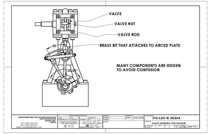
This thing is kicking my butt!! After adding all the little bits and pieces, now I can't get it to run at all. :cussing: :cussing: I've decided to go back to basics and completely isolate one cylinder and to get it running on one cylinder first, then isolate the running cylinder and set up the other one. This works great if I can get it running on one cylinder, which so far is eluding me. I must be getting close, because in one position that the valve was set, it oscillated. Flywheel didn't go all the way around---It sat there and went back and forth. That's something I haven't seen before. It seems that the secret is getting the steam valve into the right position, which for me has always been at the center of it's travel when the piston is at bottom dead center. Of course the problem is that with the steamchest cover plate in place, you can't see where the valve is, so you have to resort to measuring the amount of steam valve rod extending beyond the gland nut, in it's maximum and minimum positions, then decide on the "happy medium" and set the engine up to run that way.---And of course this may not be accurate either, because without being able to actually see the steam valve, I don't really know if it's centered or offset to one end or the other of where it should be in the steamchest.
 
You don't need air on to set the valve. Take the steamchest cover off and do it visually.

(And I don't care what you have done in the past, do it like I tell you!

1, set the valve spindle for equal maximum port opening top and bottom, irrespective of timing, as well as the half-turn adjustment will allow;

2, set the eccentric to just crack the top port open at top dead. At this stage forget about the other eccentric rod that is swung out of the way.)

Have you made the eccentrics independent, or in one piece? If they are in one piece, what is the angle between them? Not that this matters while you are trying to get it to run in any direction at all.

This puppy is going to run.
 
I have thought of making a Lucite cover plate. I may yet. Okay Charles, I'll try it your way. What are you calling the "valve spindle"? The parts I have are the valve itself, the "valve nut", the rod which travels from the valve nut down to the brass end that connects to the arced plate. When I set it to mid travel, what position should the eccentric be in? The eccentric are pinned to each other at 120 degrees lobe separation. The arc in the plate has a 30 degree included angle.
RecQQ6.jpg
 
I have thought of making a Lucite cover plate. I may yet. Okay Charles, I'll try it your way. What are you calling the "valve spindle"? The parts I have are the valve itself, the "valve nut", the rod which travels from the valve nut down to the brass end that connects to the arced plate. When I set it to mid travel, what position should the eccentric be in? The eccentric are pinned to each other at 120 degrees lobe separation. The arc in the plate has a 30 degree included angle.
Valve rod/valve spindle. Don't set it to mid travel. Set it so the rotating eccentric causes the valve to open an equal amount at each end. At this stage the timing does not matter. When that is done, set piston at top dead and set the eccentrics equal either side pointing downwards so each one is 60° from vertically down. That is it.
 
Progress report. I have everything back together but the cylinder closest to the flywheel is still acting quite wimpy. I need a break from this before I break out in hives!!! I have to go across town now and do some business, and maybe when I get home later I can try a teensy bit of adjusting on the eccentric on that underperforming side. If I'm really, really lucky, that may be all it takes. Hope--hope.
 
Today we had success. The engine ran on both cylinders, forward and then reverse. It's not video worthy yet, but it certainly made my old heart go pitter patter. I had a tough time getting the eccentrics set in the correct position on the second cylinder. I could get it to run, but only clockwise. then I would adjust it a little bit and it would only run counterclockwise. Finally, I played "Around the clock" and moved it in 20 degree increments until I found the sweet spot, where it would run in either direction as dictated by the reversing levers position and in concert with the first cylinder. At the end of the day I scrounged around in my shop until I found a piece of steel to make a second flywheel. I'm not sure if I actually need it or not, but even if I only use it during "set-up" procedures you can never have too many extra flywheels around.
 
So did you not follow the same procedure with the second end as the first? Equal port openings as before? Then set piston at top dead and the eccentrics downward at 60° either side?

For valve setting and timing you treat it as two independent engines, that just happen to be joined together at the middle of the crankshaft.

As I said before, and as others have explained (I read MEM too) you may then end up with each end trying to go in opposite directions, in which case, at one end only, swap the connections of the eccentric rods over so that they are at the opposite ends of their expansion link.

Get it right and this engine should turn over sweetly at just above zero revs with no flywheel.
 
Charles, I set up the second cylinder exactly as I did the first cylinder. The second cylinder has the two eccentrics pinned together, same as the first cylinder. There was a bit of confusion because of the "opposite handedness" of the second cylinder. I'm not 100% sure that I have it totally right, but I did find a point where the engine would run both forward and reverse. I have more work to do on the engine yet, but todays results were very promising. I have a second flywheel up on the lathe as I write this, but I'm not really sure if I need it or not.
 
Back
Top