90 degree V-twin engine

Home Model Engine Machinist Forum

Help Support Home Model Engine Machinist Forum:

This site may earn a commission from merchant affiliate links, including eBay, Amazon, and others.
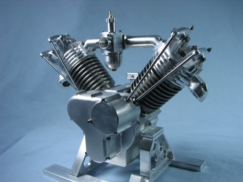
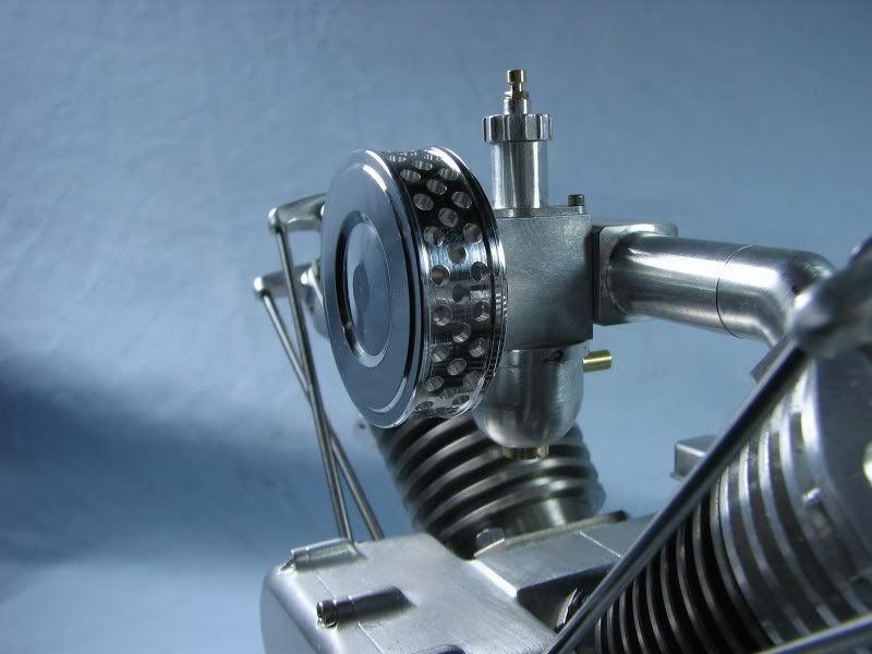
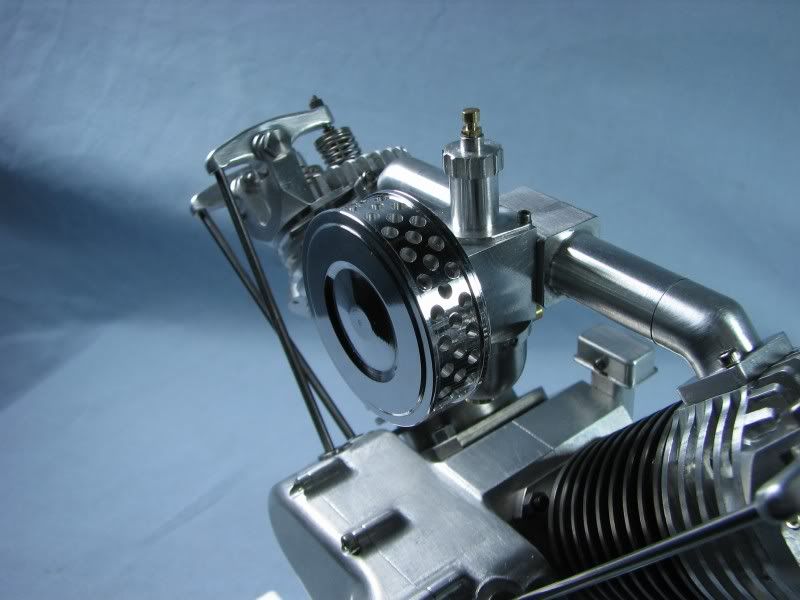
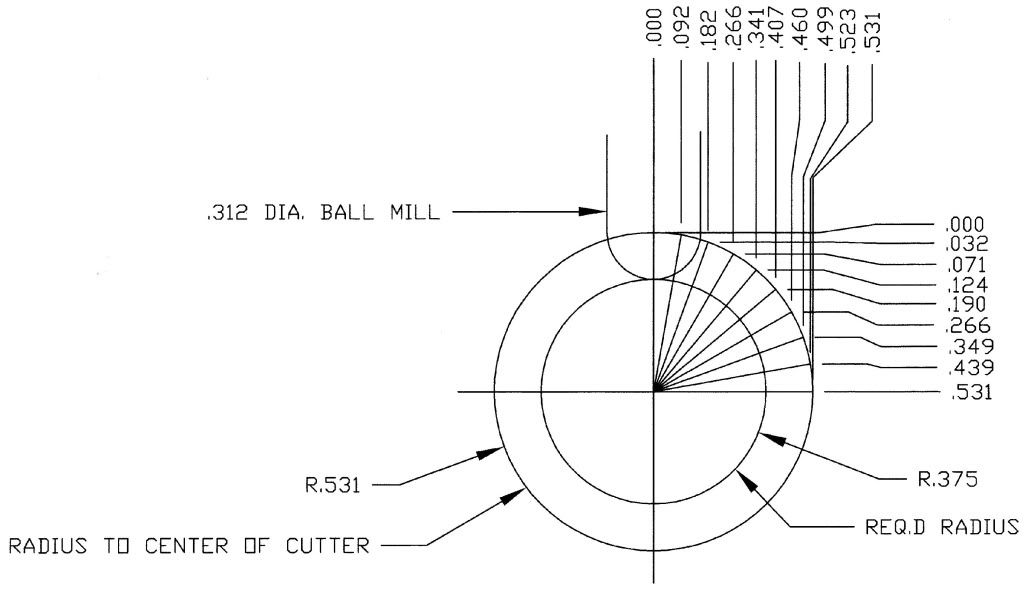
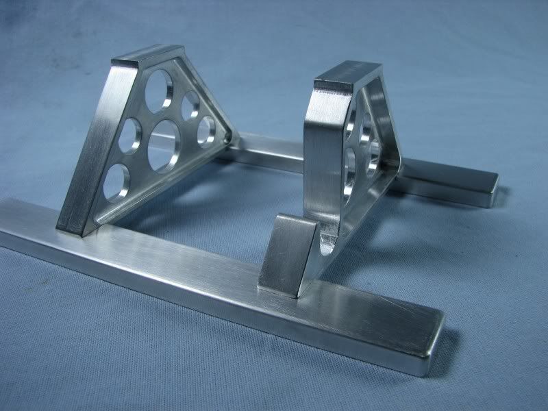
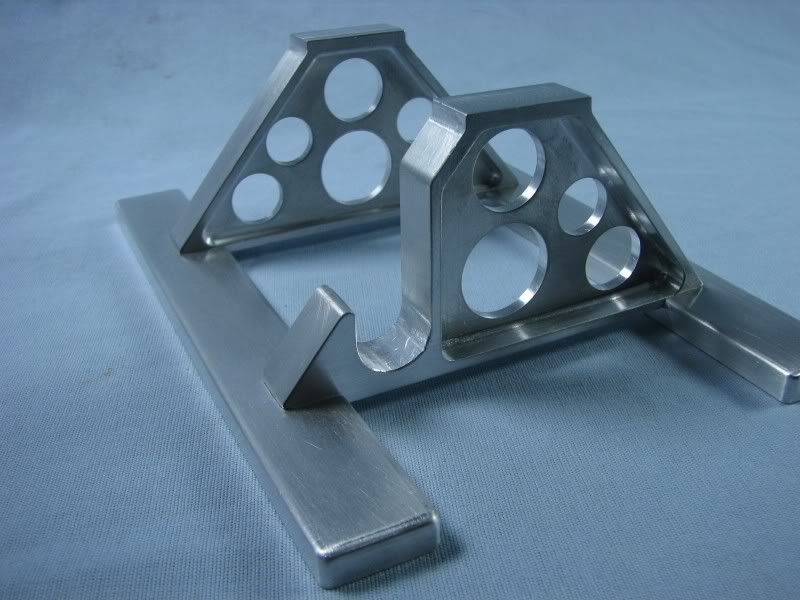
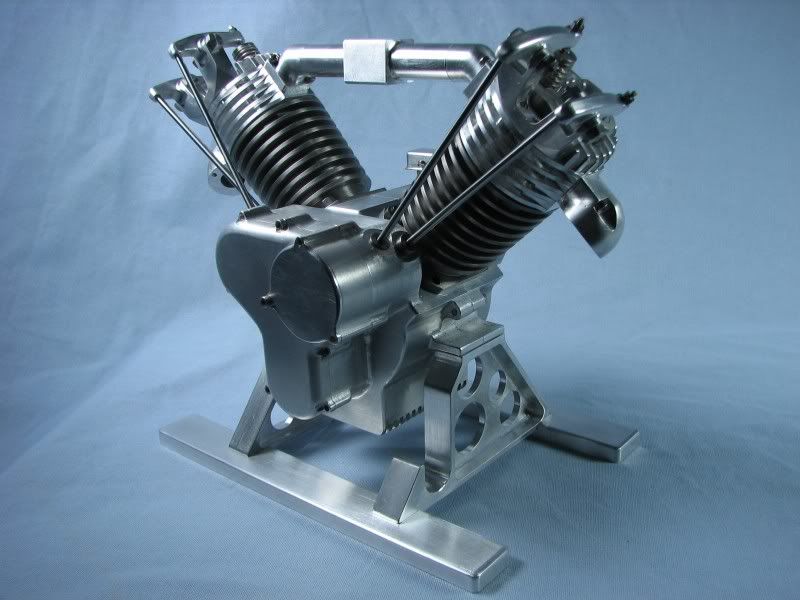
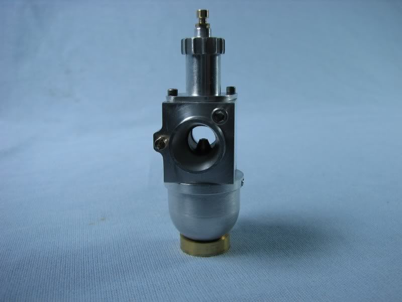
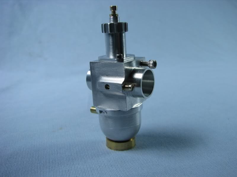
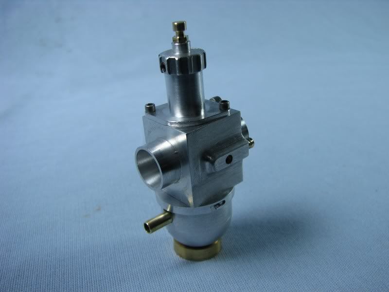
Hi Paul, if I'm doing a radius without an intersecting surface I lay out the radius I need plus the radius of the cutter in AutoCad and then put in the coordinate dimensions. The angle of the steps is determined by the cusp (the height of the bumps between the cuts). I establish the center of my part, move off center the required amount and then start stepping around the radius. When I was a patternmaker we were always machining radii into the pattern and corebox equipment. I had to do this type of thing almost daily. In trigonometry terms it's called sine and cosine. In the case of the part you posted I would do the same thing but I would have a layout line for the front face to work to. It seems tedious but after you've done it enough it's not to bad. Sometimes there is no alternative, by that I mean some parts could be rotated on a rotary table but for something small like this there would be practically no way to hold it. Most all of the radii you see in the construction of the crankcase were done this way.
George

SINECOSINE269.jpg
 
George,

I've been lurking here on your thread for quite some time. I haven't posted, since I've been speechless. You are truly an amazing individual. From your designing, to your machining ability, and your artistic hands, you inspire myself and everyone else here. Thank you for sharing your inspirations, and showing us anything is possible.
:bow: th_wav :bow:

Matt
 
oh my God...
everythings are great...but the "cast effect" looks fantastic!
 
Hi gang, I guess it's time for an update. I have been working on parts but with my big lathe being down I'm making all the small bits or pieces that will fit on my small lathe. The next piece that I finished is the base/motor mount. I wanted something to compliment the finish and style of the engine so I kicked around a few ideas. This is what I came up with. The front mount is a little different than the rear in the fact that part of it is cut away. This is to accommodate the bend in the front exhaust pipe. The pipe will then pass partly under the engine and through the hole in the rear mount. I made the uprights and then milled small pockets in the rails, .45 wide x .094 deep. The uprights were then radiused on the ends to fit flush into the pockets. They are held in place with one 2-56 socket head screw from the bottom.
NE.jpg

NF.jpg

NG.jpg


Next on the agenda was the carburetor. I have had good luck with the simple air bleed type carbs so basically that's what this one is. The bore is .260 diameter with a tapered inlet and outlet. Here again I wanted it to match the aesthetics of the engine so I tarted it up a little. I added the dummy float bowl to cover the needle valve body. The upper flange is held in place by the needle valve body and the bowl has two tabs on it that twist locks into the upper flange. In the back of the bowl is a relief pocket for the fuel tube to stick out. On the top of the carb I made an extension tube to somewhat replicate the shape of a motorcycle carb. The shaft on the rotating barrel goes up through this tube and sticks out of the top by about .100. I then made a dummy cap replicating the type of cap that holds the spring and slide in the full sized edition. I made up a .375 drill rod tool to cut the little ribs on the outer diameter. It is held in place with a 2-56 set screw. This will be the actuator to open and close the carb, just by twisting. I then got a little carried away and added the dummy fitting where the cable adjuster is on the top. The socket head screw on the front is to hold the barrel in place and to adjust the stopping point for the idle. The brass screw is to adjust the air bleed on the side. Once the engine is running and adjusted these will be shortened and locked in place so they don't protrude as far. The body is aluminum, the barrel is 303 stainless and the needle valve body is brass. I used a hard bronze for the needle valve. I held it up to the intake manifold on the engine and it looks quite realistic. I might do a little more sculpting on the sides to refine the shape even further.
George
NH.jpg

NJ.jpg

NK.jpg

NL.jpg

NM.jpg


Very beautiful work.

Your an artist with metal. :)

How long (roughly) does it take for you to make a piece ike that from start to finish.

It's the craftsmanship of the builder, that makes the piece,
but is there any special tooling or somethin...

I don't know I guess my question is,

Does this stuff just come to you naturally, are you a natural born artist with this kind of work, and I do mean this with all due respect. :)

OR, did you have to learn this through trial and error, with lots of time and materials invested to get the PERFECTION, that you are getting in your workpieces???

Hope ya don't mind me asking... ;)

Thanks...

 
George,

It just keeps getting better :bow: :bow: :bow: :bow:

NICE

Jeff
 
George, the carb is a showpiece in itself. It looks fantastic.

Dean
 
Hi Hobby, first thanks for the accolades. I'm not quite sure what particular piece you're referring to so you'll have to be a little more specific. As far as the way I go about making my pieces I guess part of it is the talent that I was born with. I don't mean for this to sound facetious but it's just the way I do things. The second part of that is I was trained as a metal patternmaker and pattern designer so I had to look at the way parts were made and how I could replicate them as a casting. As far as trial and error, I've had my share of mistakes along the way but I've been doing this for a very long time so I've had time to learn from them and hopefully not repeat the ones I made.
I take no offense to anything you said, in fact I'm very appreciative that you would ask.
gbritnell
 
George,

Every time I visit this thread I am absolutely blown away by your work. I can only hope to reach something approximating half the level of skill you exhibit with this project.
 
Hi George.

Thanks for replying,

Don't worry, it is NOT, taken as being facetious,

there is nothing wrong, in, ac_ knowledge_ing, a God-given talent.

You have taken that talent and refined it with years of experiance,

and the results show..

Your build threads are very encouraging to go the extra step, in a setup, or taking the time neccessary, to produce a better looking part, rather than just settle for mediocre,

Thankyou for living up to your quote at the bottom of your posts.

Your talent being shared with us is, what gives us the incentive to go farther in our builds.

Have a great day...

Again,...Those, are beautiful, workpieces..


PS, ...

from up above in my post 4th sentence down...

"ac", looks right, "knowledge" looks right, "ing" looks right,

BUT......putting it all together "acknowledgeing" dosen't look right,
maybe that last "e" gets dropped, but when I drop the "e"

"acknowledging" still looks funny, :-[

any way everyone thats why the spaces in that word up above... ;D
 
The next step was to bore the hole in the manifold for the carb. I put it in the mill because it was easier to pick up the centers and put the rough hole in. After that I put it in my four jaw chuck on the lathe, indicated the hole and bored it to a nice snug fit for the carb. There will be a small set screw in from the bottom to hold everything secure. With that done I mounted the carb and took a couple of pictures.
It's looking more and more like an actual motorcycle engine.
George

NN.jpg

NO.jpg

 
Next up was and air filter plate and cover. Although there won't be any filtering material I just thought it would add a finishing touch to the carb. With the throttle stop screw and the air bleed screw protruding from the carb I didn't have enough room between the head of the screw and the outer diameter of the inlet to make a thick enough flange so I went beyond the screws and then relieved the rest of the material away. With this setup I can adjust the screws without removing the backing plate. The cover was machined and buffed before drilling the holes. I had found out years ago that when you buff over a hole it rounds the edges so by buffing the part first and then drilling it leaves nice sharp edges on the holes. Once buffed it only requires a little polish now and then to bring the luster up. The cover is a nice snug fit on the backing plate so no mounting screw is required. As for the buffing, I thought by adding a touch of shine here and there it would just set off the other finishes on the engine. I think I will do the oil breather cap also. Next up will be a bender for the exhaust pipes.
George

NP.jpg

NQ.jpg

NS.jpg

NT.jpg


It's a good thing that I sit down when I look at your posts.

It's closer to the floor! :big:

Tony
 
It really is mind blowing, I actually got the shivvers and goose bumps when I saw the engine on its frame then. Just incredible.

Many thanks for sharing this with us George.

:bow:

Nick
 
It's just amazing to me that this stuff can be done by one man and his brain.
What an example to follow..

Dean
 
Works of art, Goerge,
excellent workpieces...


I realize a lot of filing and sanding go into your workpieces,
but if I bought a buffing wheel for my (bench grinder), would that be all I need
to get a somewhat shiney finish on my parts, than the dull finish that aluminum aquires with age?

Also how do you keep a shiney finish, on metal, by using a urethane of some sort?

Thanks...

 
:eek: :eek: :eek: :eek: :eek: :eek: :eek:

I have no more words to describe my feeling when watching at your work

 
Once again I thank everyone for their more than gracious comments.
Hobby, In preparation to buffing aluminum you need to progressively sand the metal to the point that there are no scratches in it. At that point it takes virtually very little buffing to get the metal to a high luster. I use a sewn cotton buff on my bench grinder for the big areas and small felt buffs for small pockets. The buffing rouges come in several grades, red, white and brown. Each one has a different cutting ability. I generally use the red for aluminum. A word of caution, always buff from the metal toward the corner and not into the corner, if not you will round over the edge. And believe me it doesn't take much to round the corner. Another thing to watch when working with the small buffs, apply light pressure and keep moving. It doesn't take much to polish little valleys into the metal. They might be only .0001 deep but when the light reflects off of them it gives the surface a wavy finish. On coating polished metal, I don't do it. As long as the parts, brass mainly, aren't handled alot, they will hold their shine for a long time. The problem I've found with overcoating with a clear lacquer or such is that if it starts to tarnish underneath the coating then the entire finish must be removed to re-clean. It's just easier to polish the base metal.
George
 
Back
Top