90 degree V-twin engine

Home Model Engine Machinist Forum

Help Support Home Model Engine Machinist Forum:

This site may earn a commission from merchant affiliate links, including eBay, Amazon, and others.
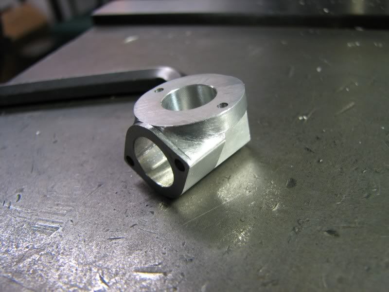
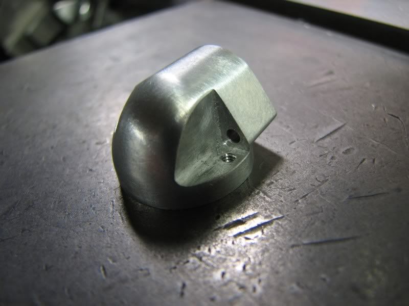
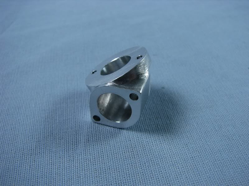
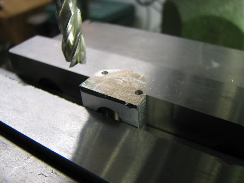
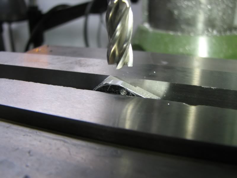
I lightly clamped the piece in the vise and cut it to length, .800. You can see where the drilled holes came through the part.
ME.jpg


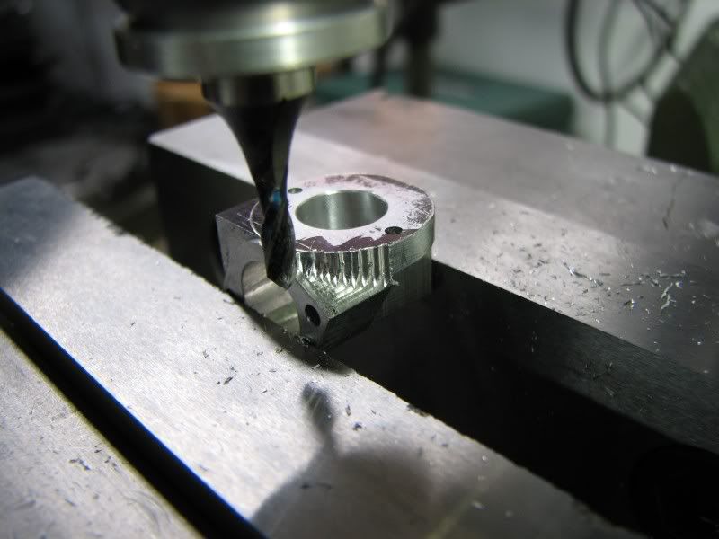
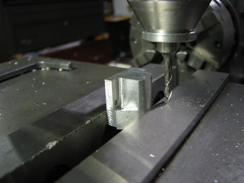
The part was raised in the vise to give enough room to cut the clearance for the screw heads. I needed to cut for .075 radius but not having a .150 end mill I just used a .125 and shifted it .012 on both sides.
MG.jpg


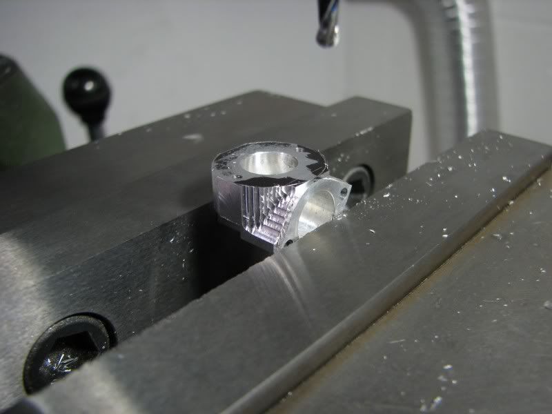
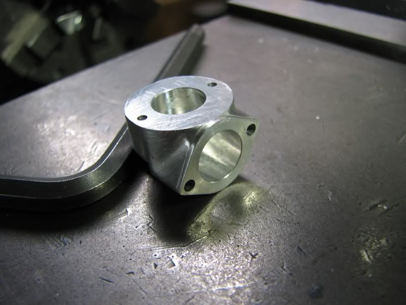
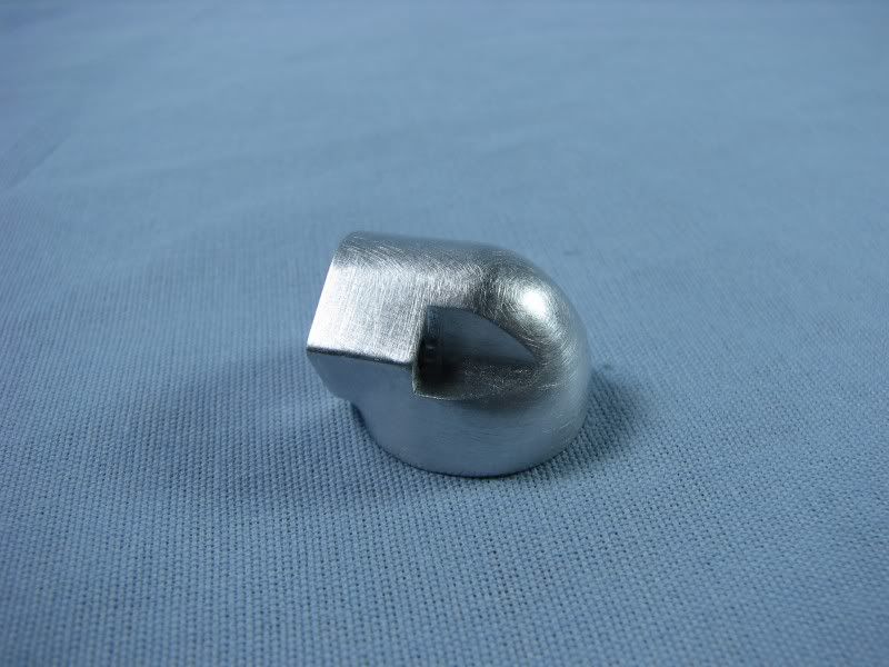
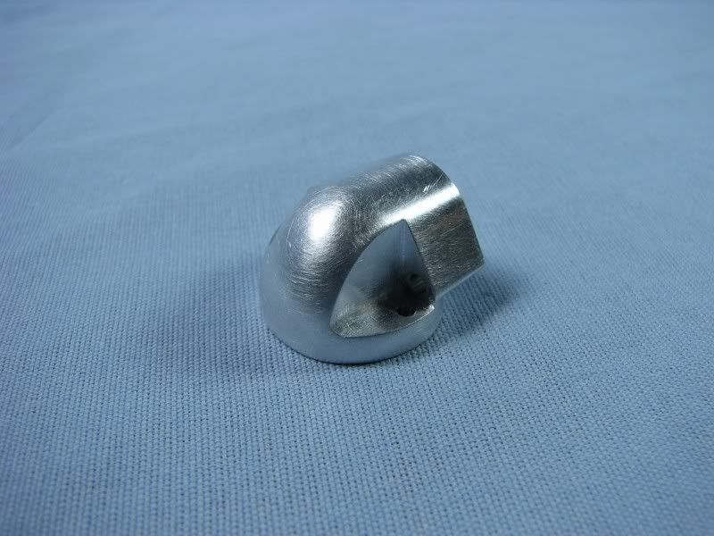
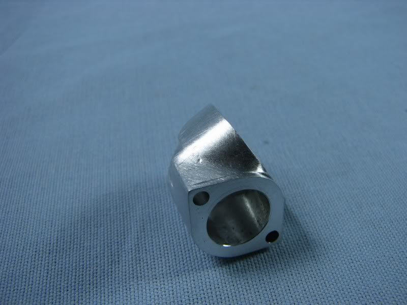
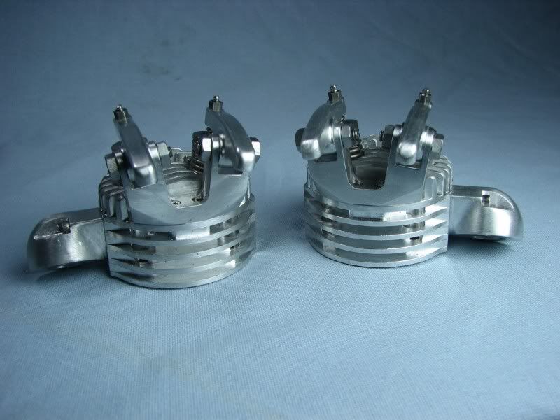
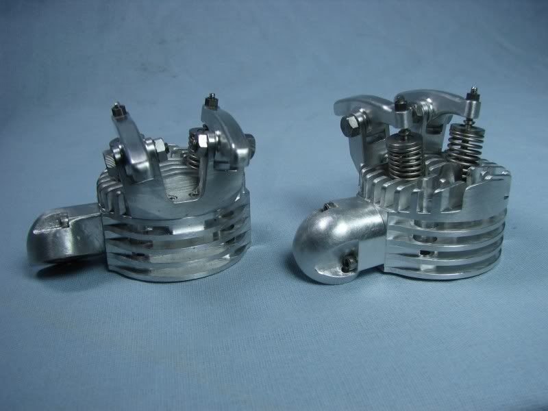
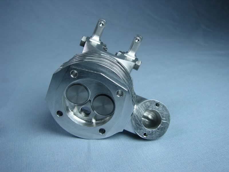
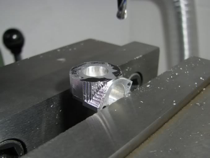
The next step was to start trimming away the extra stock to form the circular shape on the outlet flange. I turned up a plug to fit in the port and also the diameter I would need to scribe the layout and do the final fitting to. With the face blued I scribed a layout line around the plug.
MF.jpg


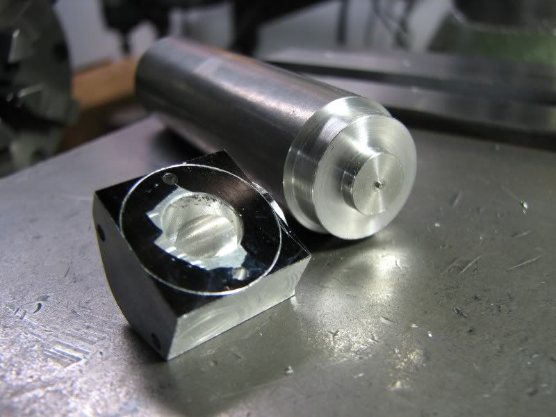
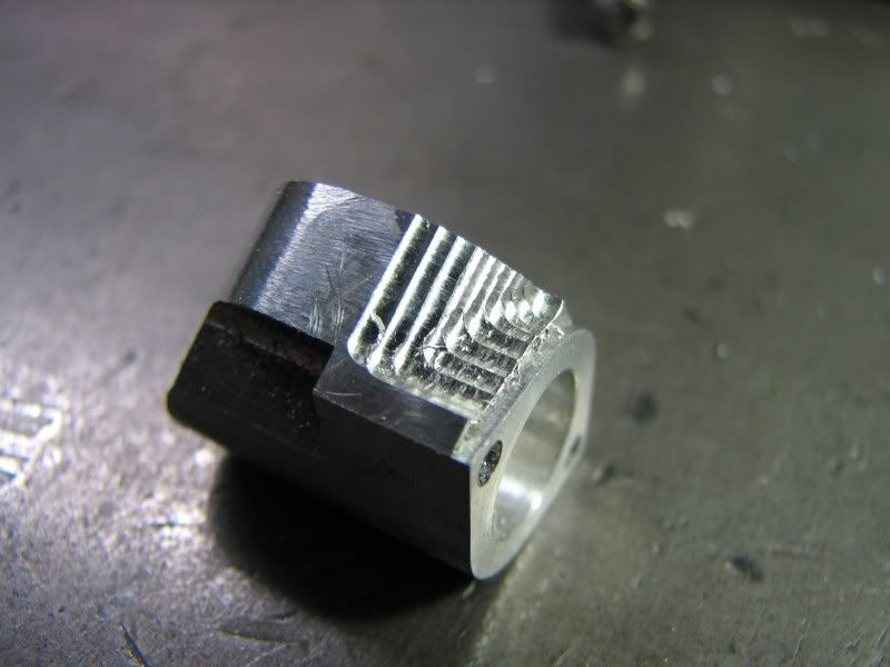
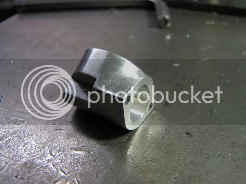
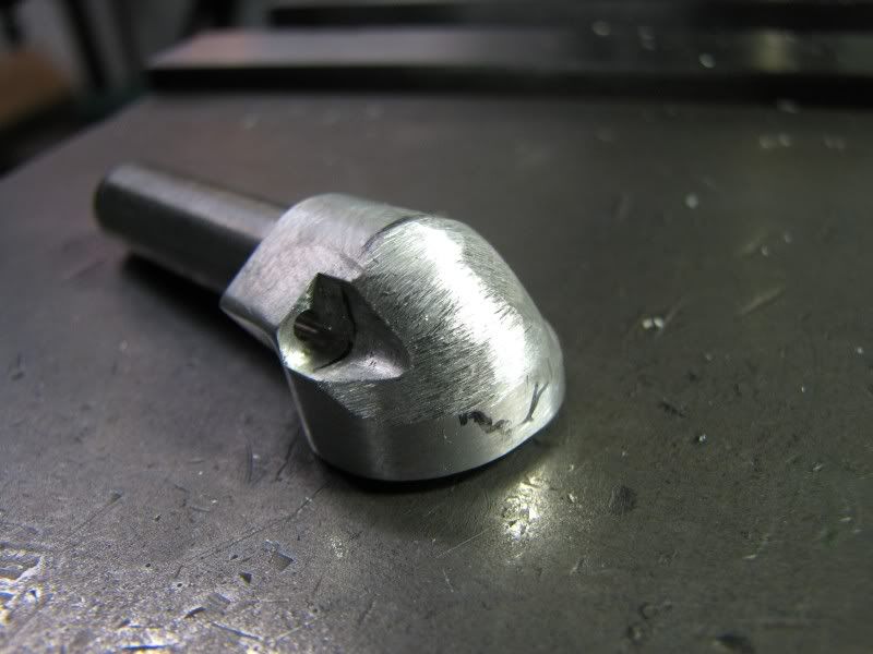
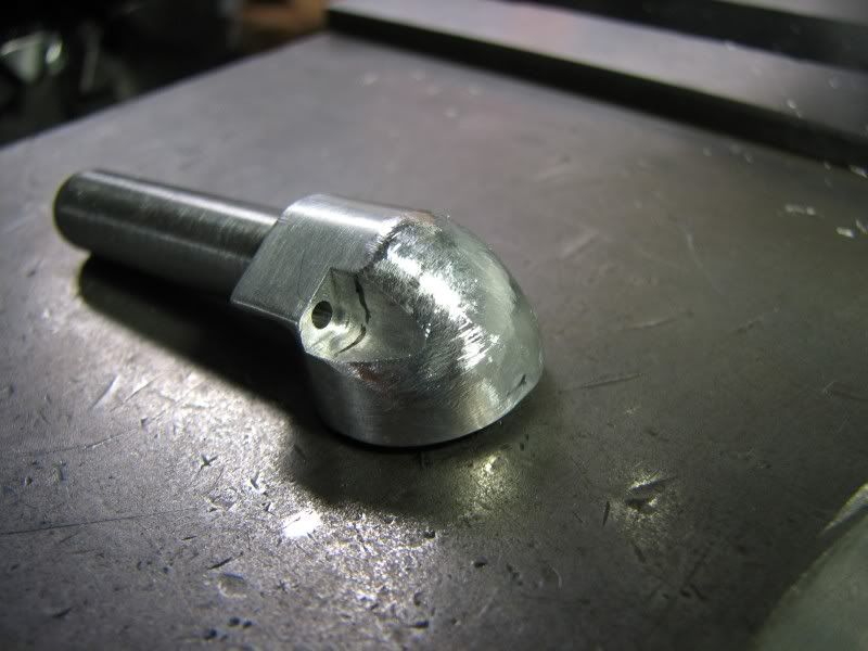
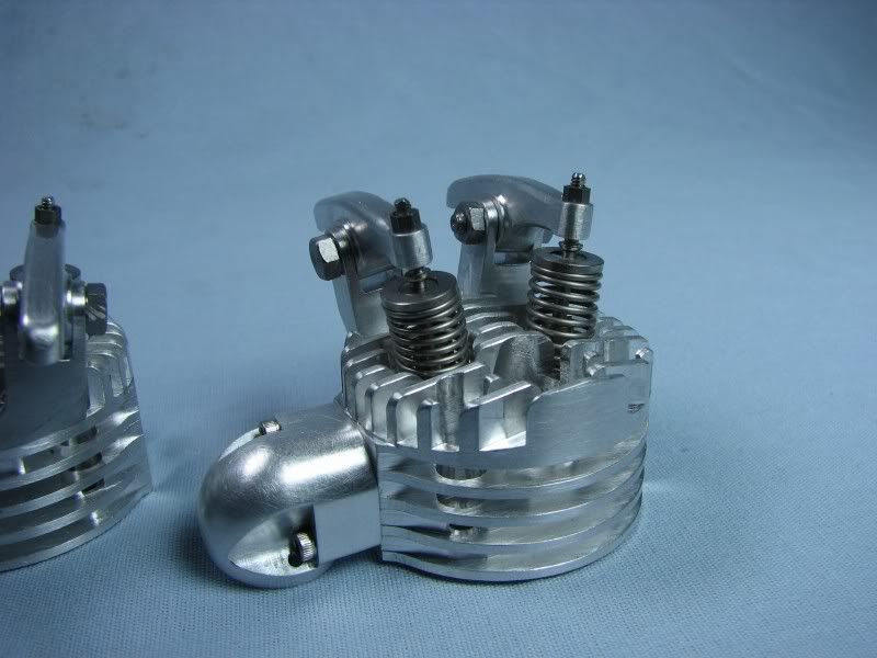
The outer shape was just a matter of nibbling away the stock close to the line.
MH.jpg


Cutting the radius on the inside would require using a .125 ball mill. I touched the outside of the part and went in .020. I worked my way down to the angled face on the flange and cut back till I just bumped the layout line.
MJ.jpg

MK.jpg


After successive cutting and stepping this is what the part looked like.
ML.jpg


Now it was over to the bench for a little work with the Dremel, some filing and finally some sanding and polishing.
MM.jpg

MN.jpg

MO.jpg


The next operation was to form the outer radius around the end of the fitting. I roughly layed out my centers with a small tipped marker and then with the part held with a dowel pin in the port I roughed it out on my belt sander. The first picture show this. The next picture is the part with filing applied. Working both along the spine and over the sides with the file I formed a nice radius continually checking with my radius gauge.
The final picture shows the sanding done on the radius.
MP.jpg

MQ.jpg

MR.jpg


I took the part up to the utility tub and scrubbed it with cleanser and an old toothbrush to get that nice satin finish. Here's four shots on my photo table.
MS.jpg

MT.jpg

MU.jpg

MV.jpg


George, I just marvel when I track your parts from a piece of metal to the finished product. You end up with all the details of a nice casting. Is that how you visualize the part before you start cutting or do you model it with CAD?
 
These last series of pictures show the flanges bolted to the heads. If you hadn't noticed they are symmetrically opposite parts because of the angle that the exhaust pipe will have to go. You will also see that I have installed the valves and springs into the heads. I purchased stainless steel, .375 OD. x .035 wire springs. I had to cut off about 3 coils to get them to the right length. I have wound springs in the past but it's not one of my favorite jobs. With these parts done, the cylinders honed, the pistons and rings made I can clean and assemble all of the parts. Once everything is fitted with the necessary gaskets I can start constructing the intake manifold. I will have to use the engine as a jig to build it so everything has to be in it's proper place to finish it up.
George

MW.jpg

MX.jpg

MY.jpg

MZ.jpg

NA.jpg


Hi Arv, the parts are only drawn in AutoCad. Although I have a 3d modeling program I don't use it. Having been trained as a patternmaker I know where all the fillets and radii need to be. It takes much more time to do it this way but to get the cast look to it there is no other way. If a person had access to CNC equipment the part could be modeled and cut but for something like this piece it would require a 4th axis CNC to rotate it to get to all the surfaces. I do it the old fashioned way, hand CNC, LOL!!!
George
 
Dam George,
That is some awsome work :bow: :bow:

Tony
 
I continue to marvel at your talent George. Very Very Nice :bow: :bow: :bow:
 
gbritnell said:
I made up 8 piston rings, just to be safe. I use the George Trimble method for making rings and have had good success with it.

I am going to look into that method. The rings in the peewee suck. Must have lost tension. Smokes more every time i run it.

Looking great G!!
 
Thanks again for showing us in a step by step sequence, George.

Although these two ports on their own may be somewhat overshadowed by the engine as a whole, they are full of setup and cutting/tooling tips. Besides that, they're beautiful, as with everything you've shown us with this engine.

A lot of the best machining education some of us will ever get is to be seen in this one thread.

I surly appreciate it.

Dean
 

Beautiful pieces you've made George.

Some fine art indeed!
 
Stunning as usual, I just don't know how you do it - amazing :bow:
 
George
I remain in awe of your work. Those heads are works of art themselves.

Steve
 
Hi everyone. Just a little update on my progress. I had to notch the bottoms of the cylinders a little bit for rod clearance. I made Teflon head gaskets. I made the intake manifolds. I should have documented them but at the time I didn't think they would be as much work as they turned out to be. I had debated how I was going to make the manifold with the bends and flanges. My original design was to make the assembly out of brass so that I could silver solder things together. After some thought I decided to make it out of aluminum to keep everything uniform. I thought of making the flanges and then bending some aluminum tube and welding them together but finally went the way you see in the pictures. I machined the manifold elbows from a piece of .75 round stock, drilling and cleaning up with a .375 ball end mill. I removed the stock behind the flange with a small necking tool taking it back to the start of the bend. From there they went to the mill to cut away the extra stock from the pipe shape and the flanges. They were then set up at 45 degrees and the matching hole was put in and the stock around the outside was stepped off to form the radius. After machining came all the hand work. The connector tube was turned from a piece of .75 diameter aluminum. The through hole was drilled and the outside was turned down back to the carb box. On the end I reduced the diameter so it was a good snug fit into the elbows. At final assembly I will probably Loctite the three pieces together. The pictures show my progress to this point, one from the front one from the rear and a closeup of the manifold flange. I have ordered the stainless tubing for the exhaust and I purchased some Cerrobend low temperature alloy to aid in bending. My tubing bender only goes up to 5/16 tube so I will have to try and bend this around a piece of stock with the alloy inside the tube to keep it from collapsing. I am going to start out with a carb similar to the one on my OHV engine. I only have a few more pieces to make, carb, motor mounts, ignition parts and exhaust pieces and then I can tear it apart for the final fitting. Here are today's pictures.
George
NB.jpg

ND.jpg

NC.jpg


I could look at these pictures for a long time. It's really a beautiful piece of work, George.
 
That crankcase looks like a highly polished precision casting.
Knowing that all of those were contours were machined and hand
blended is mind boggling.

I'll say it again, Beautiful Work George! :bow: :bow: :bow:

Rick
 
Hope you're going to get that thing insured! Brilliant. :bow:
 
George,


Absolutely beautiful! Can you tell us a little more about machining sculptured surface with conventional milling equipment.

gbritnell1.jpg


For example, the compound fillet on your exhaust manifold. You stepped milled at pre-established locations to prescribed depths. How did you arrive at these locations and depths?
 

Latest posts

Back
Top