1" Bore x 1" Stroke Vertical i.c. Engine

Home Model Engine Machinist Forum

Help Support Home Model Engine Machinist Forum:

This site may earn a commission from merchant affiliate links, including eBay, Amazon, and others.
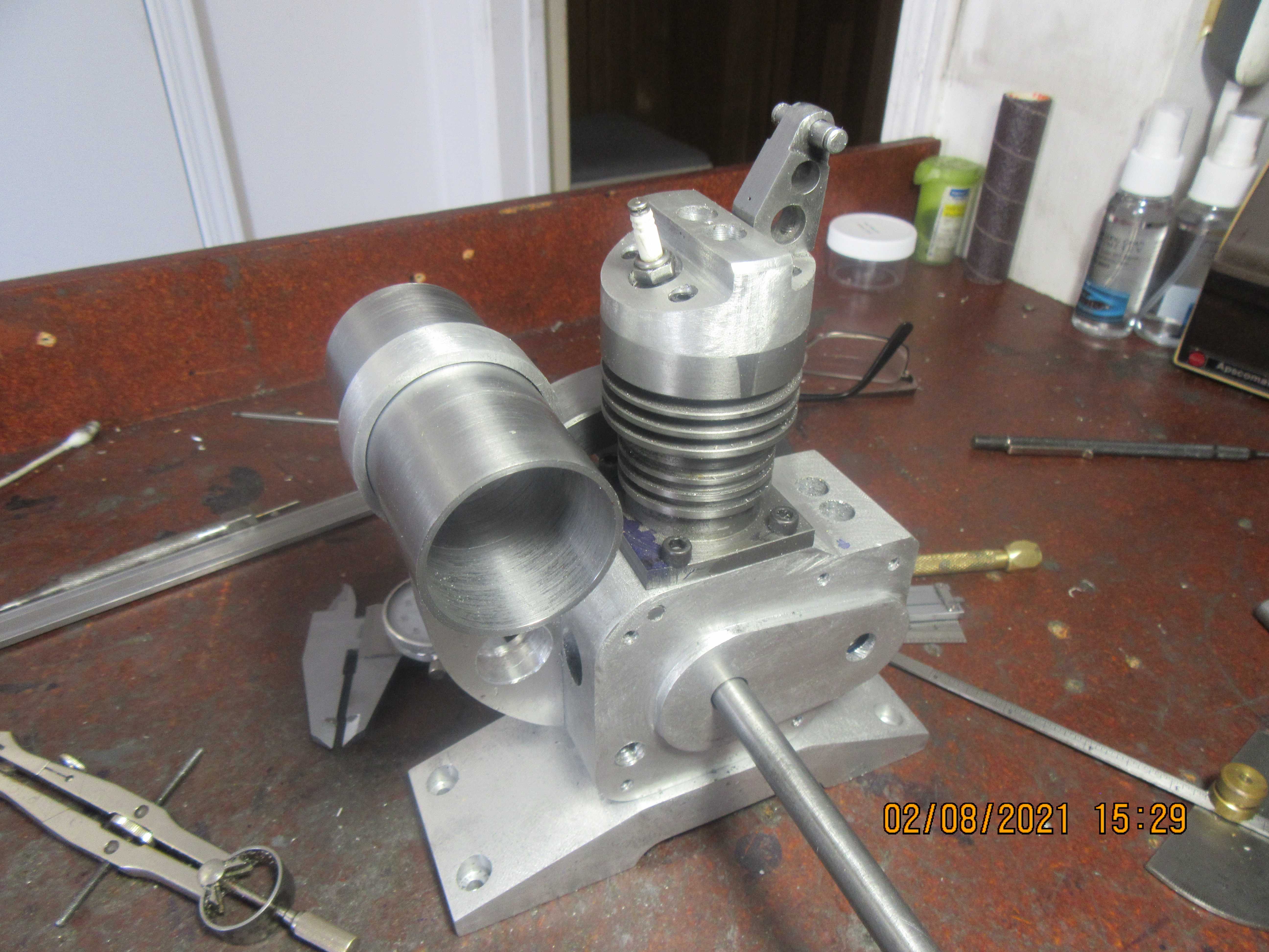
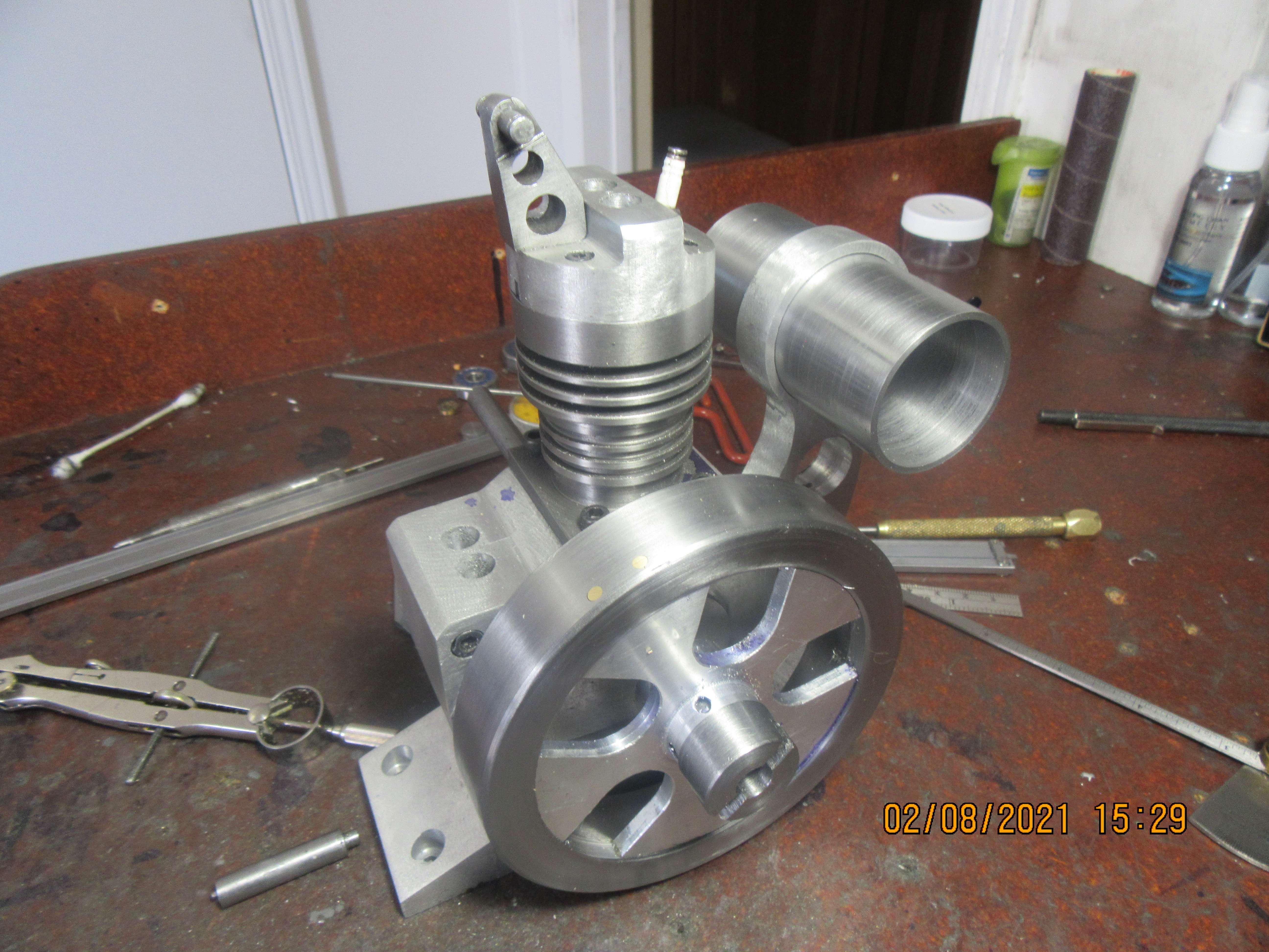
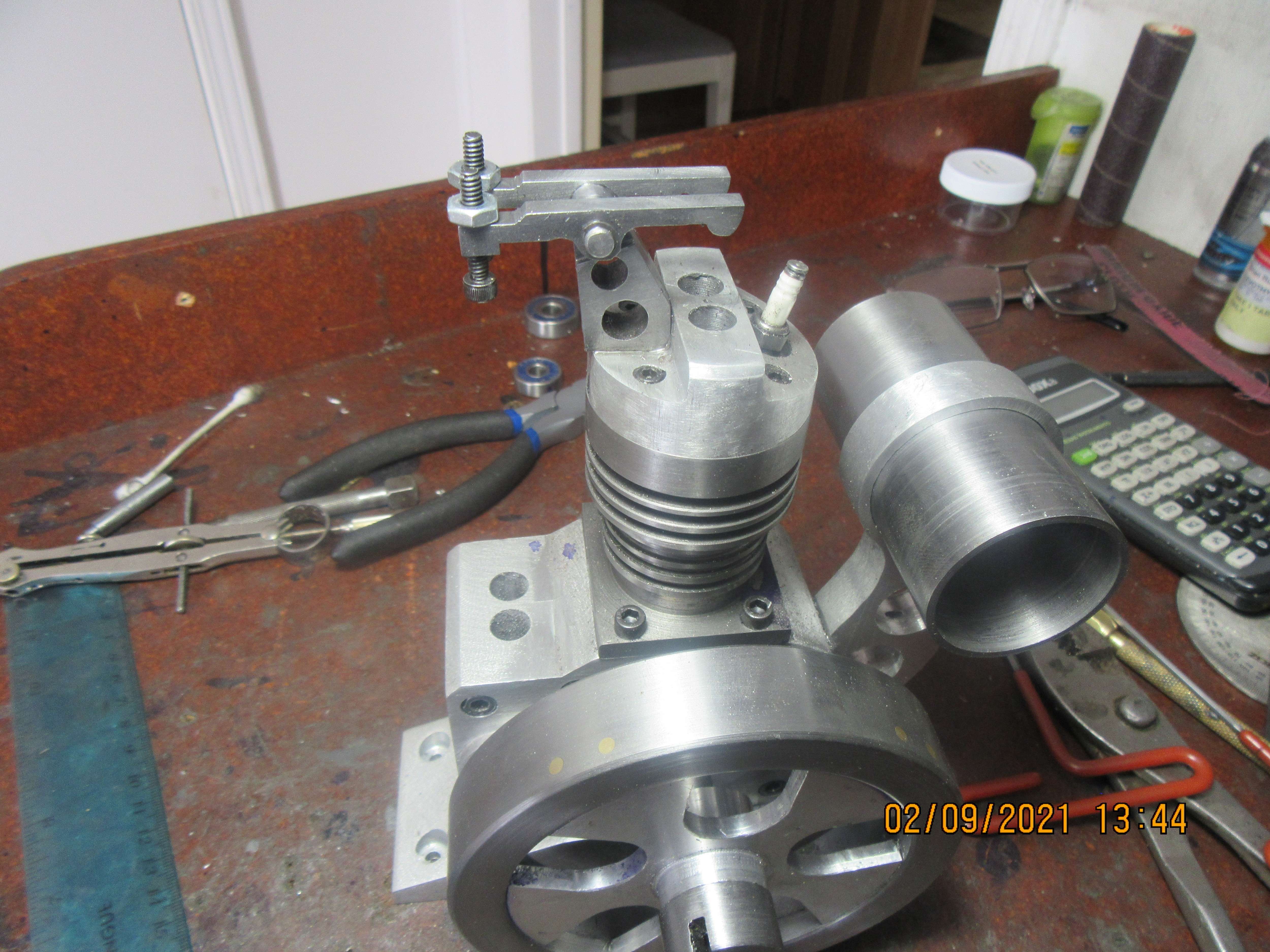
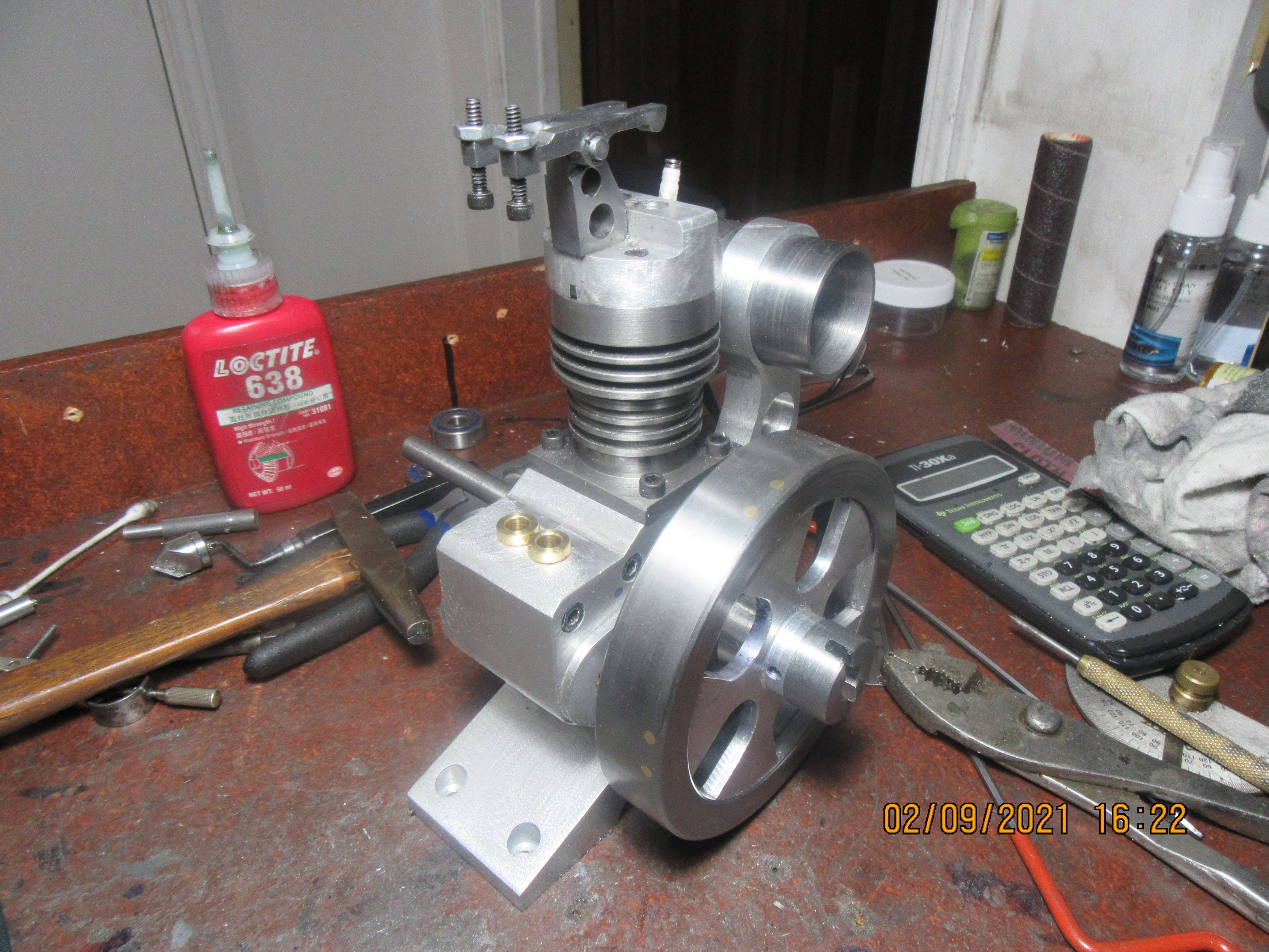
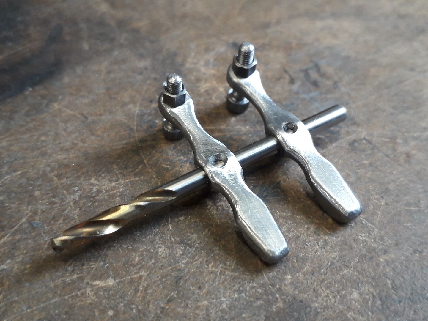
I had the devil of a time with this rocker arm tower. Had no problem making the large piece which bolts to the cylinder head. I reamed the top hole with a 3/16" reamer, and then decided that rather than silver solder the rocker pin into it, I would machine it to have a press fit. I started out with a piece of 1/4" cold rolled and machined it to be about 0.010" oversize. then I decided to take the remaining bit off with file and emery paper, aiming for 0.189" diameter for a press fit. I sanded, and I sanded and I filed and I filed, checking every 20 seconds with a micrometer so that I didn't turn it undersize. I eventually got it down to 0.189" and started to press it into place, heating the larger part with my oxy acetylene torch to expand it a little---and it went crooked!!! Then I had to take it apart, straighten it out (burned the Hell out of my finger doing so). Then I was successful in getting it pressed into place, but I'm sure glad I wasn't paying myself machinists wages, because it took about four times longer than it should of. The good news is that while I was rooting around in my box of goodies looking for a 1/4"-32 sparkplug, I found a couple of 1/8" ball bearings that I didn't know I had. They will be perfect for my cooling fan shaft.
k6jLRw.jpg

44zImv.jpg
 
I've spent a bit of time sussing out the cooling fan, using the bearings I found earlier today while searching for a sparkplug. As it turns out, they weren't 1/8" after all, but were 3 millimeter. (which is about 0.118"). That's okay, close enough. I can make them work. I don't see any problem with the support bracket nor the pulley, but I'm afraid that if I make a fan it will look like it was made by a cave man. It's difficult right now with this Covid thing, because I can't actually go over to Sayal Electronics and look for a fan. I've looked at a great number of fans on the internet, but for something like this I'd really like to see it before I bought it. The fan as shown is 1 5/16" outer diameter with a 3mm center hole and it blows towards the cylinder, turning clockwise when viewed from the flywheel side of the engine. I could use a 35 mm diameter metric fan. I'm not sure just what I'll do, but I'm happy to get the bracket designed and to have found some bearings.
iM4BPs.jpg
 
I wouldn't go so far as to say I HATE making rocker arms, but they are not something I'd machine for enjoyment. And they're stuck right up on top of the engine for God and everybody to see, so they have to be done right. I've managed to use up an entire morning making these ones, but they look okay. I'm running out of "easy" things to make, but I still have some lifter guide bushings and the gas tank assembly to finish.
YjwTOy.jpg
 
Hi Brian. I guess you dissassemble later to drill oil ways for rockers, etc? I guess you'll put a pretty little brass oiler on top of the rocker shaft mount to feed them? That will catch the eye and distract from the rocker arms I think?
I'm not bothered about the appearance of the rockers the way you suggest, but you could mill some grooves either side of the rockers to lose weight and make them look like "H" section castings? Knowing your work they'll be a real good looking feature then.
Cheers!
K2
 
There!! Enough work for one day. I see that I have mislabeled these lifter guides as valve guides. Oh well, I can change the name tomorrow. Going upstairs now to drink Kahlua.----Yes the rockers are steel.
Ecwmww.jpg
 
Steamchick---I'm not that sophisticated. No oil holes or galleries for the rockers. Just a squirt of oil before running the engine.
 
Brian, is the gas tank steel, too? Are you going to put on a glass end cap or something pretty like that or something like a pipe cap?

The way I interpreted the drawings back on the early pages was a glass cap.
 
The gas tank is steel. I have been dissed by a fellow forum member on how big and clunky the pipe caps I normally use for gas caps look, and I think I agree with him. I don't think I will use any glass, but I will probably come up with something a bit sleeker looking. I haven't totally thought it through yet, but stay tuned, it could happen this week.
 
No Probs Brian. I am thinking more of a guy who shows his engines at our club events: Always complains that his models wear too quickly, but he doesn't make any provision for oiling, and runs long periods.. If your engine was powering something for any length of time I guess you would add some oiling. One guy built a 9 cylinder radial - said it only ran once before everything rattled and he lost compression - so never run since. He said he wasn't going to build the plane for it - so it didn't matter. Sad that all that work had such a short life. But there you go... I come from industries where the product has to last decades, or hundreds of thousands of miles, so lubrication is a prime consideration for me.
K2
 
The rockers don't really use enough oil to warrant fitting oil cups and you would likely need caps to them so the rocking did not slosh the oil about. I tend to use a very small ctr drill to make a hole with CSK edge which is enough to hold a drop of oil applied as needed.

As for shape you can go at them with a needle file to soften them up a bit and file the main profile so it's a bit more organic or if you have CNC some fancy curves become a lot easier. Add to that turned and straight knurled adjusters rather than cap screws and smaller hex lock nuts if you want a less industrial look. At the end of the its whatever makes the individual builder happy that really matters.

20190817_144023_zpsfgp10cqt.jpg
 
Look nice!
My idea was for a single oiler in the post, with drilling to the rocker bearings.
In terms of shape, I spent most of my design career working shapes to minimise stress raisers and material. I had to double the dynamic performance of a job, while reducing cost by 25%.... not easy, but did-it while increasing the Service interval by a factor of 10. So I am keen to see other clever design ideas applied, rather than just Victorian engineering. Each to his own.

K2
 
Today I seem to be suffering from a bad case of "lazy arse". I don't feel like doing much. Maybe today I will prepare a couple of gear blanks. If I find any energy later in the day, might even cut teeth on them.
38RNPt.jpg
 
I like cutting gears. The more you do it, the easier it gets. As long as you have the right cutter selected---and as long as you have the cutter vertically centered on the chuck---and as long as your depth of cut is set right---and as long as your carriage stops are set so you don't run a cutter into the hardened chuck jaws and ruin it---and as long as you count the number of rotations and remember to move the sector arms each time you cut a tooth--and remember a little cutting oil once in a while, why, there's nothing to it!!!
wzfp1T.jpg
 
Easier if you have a gear hobber, which I do. Unfortunately I don't have a 24 DP hob. I only have 20, 32, and 64. Wonder if I can change a couple dimensions and still build your engine? I'll have to look into that.
 
Jkimberln--Let me do a little research on this. I'm pretty sure that there is a little gear magic that works with 32 and 64 dp gears. The only two sure things right now are the center to center distance which is 1.563" and that it must be an exact 2:1 ratio. I will delve into this and post what I find out. A lot of people want to build this engine.---Brian
 
Last edited:
I also have a gear hobber. I have equipment to make my own form-relieved hobs, but only can do D.P. not module. Those I have bought on Amazon, from China. Delivery is not speedy (a couple months) but they have been good and at $80.00 the price is right. You could look there for a 24 DP hob.
 
Okay, this I have found out so far---For 48 DP gears, they would have twice as many teeth so it would be 50 tooth and 100 tooth combination but the center to center distance would stay the same as I currently have for the 24dP gear teeth.--For 32DP gears, a 32 tooth and 64 tooth would give a 2;1 ratio and a 1.563" center distance.
 
Last edited:
I've looked into the gear DP idea too and with what I have available, the easiest way to make the gears is to use 1.0 mod and cut the teeth a little deeper in order to get the tooth clearance. That way, the tooth count and the ctc distance can remain the same. Not ideal but it would work. I also considered a couple pulleys and a timing belt but that might screw up the looks of the engine, plus a tensioner might be needed. I have a couple queries out for hobs and there is the Chinese suppliers as Poppy mentions. I hear tell that Ash Gear will also rent hobs but I've never tried that and it would probably be too expensive.
 
I hear you Brian, making gears is fun, but like you said there is a lot of "as long as yous..." I find my self holding my breath with each cut, each increment of the indexer, thinking to myself, "all right, I haven't screwed it up yet, only thirty seven more to go."

You are making great progress. It is already a great looking engine. What people don't see is the behind the scenes work on the CAD model and creating the drawings. 👍
 

Latest posts

Back
Top