1" Bore x 1" Stroke Vertical i.c. Engine

Home Model Engine Machinist Forum

Help Support Home Model Engine Machinist Forum:

This site may earn a commission from merchant affiliate links, including eBay, Amazon, and others.
Someone asked the other day what the oil level in the crankcase would be. The oil level is determined by a removeable plug in the side of the crank case. This picture shows the oil level.
4tZ55t.jpg
 
In the time honored offered tradition of "Making it up as I go along", today I have a con rod up on the lathe. The overall shape of the con rod, the bolt on cap, and the bores in both ends are finished in previous steps. Here I have made up a simple fixture to which I can attach the con rod in order to turn meat away from both sides, so I end up with a raised "boss" at the big ends. What is shown is the first step, machining the side material away to expose the first big end boss. Now I will flip the part over in the fixture and do the other side "big end boss". I will probably finish up the other ends with my rotary table and milling machine.
uRjkNF.jpg
 
Todays fun limit has been reached. We have a finished connecting rod. Sometimes I wish I had a media blaster to even out the finish on things I machine so they would show up better on camera. ah well, nobodies going to see it once it's installed in the engine. It is aluminum 6061 t6 material. I don't generally put bronze bushing shells in these con rods, as they never see heavy lugging loads and aren't run often enough to make a difference.
XGAoRt.jpg
.
 
Looking good Brian. If you are to make another fan, what would you think about a thin strip of metal wrapped around the outside of the blades to protect a finger that strayed too close when the engine is running. Think of a section of tin can cut to match the outside diameter of the fan--that sounds dangerous too. Or maybe a shround integral to the mount?

I remember the time I was reviewing an electronic packaging design that had an exposed running fan. I pointed to it and asked the engineer with me, "shouldn't that fan have a grill over it?" And it took the tip of my finger right off.
 
Look at the solid model. The exhaust system sets directly above the fan (see post #136). I know the fan is there, and I know not to stick my finger in it. I no longer have to deal with "Safety Committees". They were the bane of my existence!!!
 
Here's a picture of a half grown piston. It will reach adulthood tomorrow. 
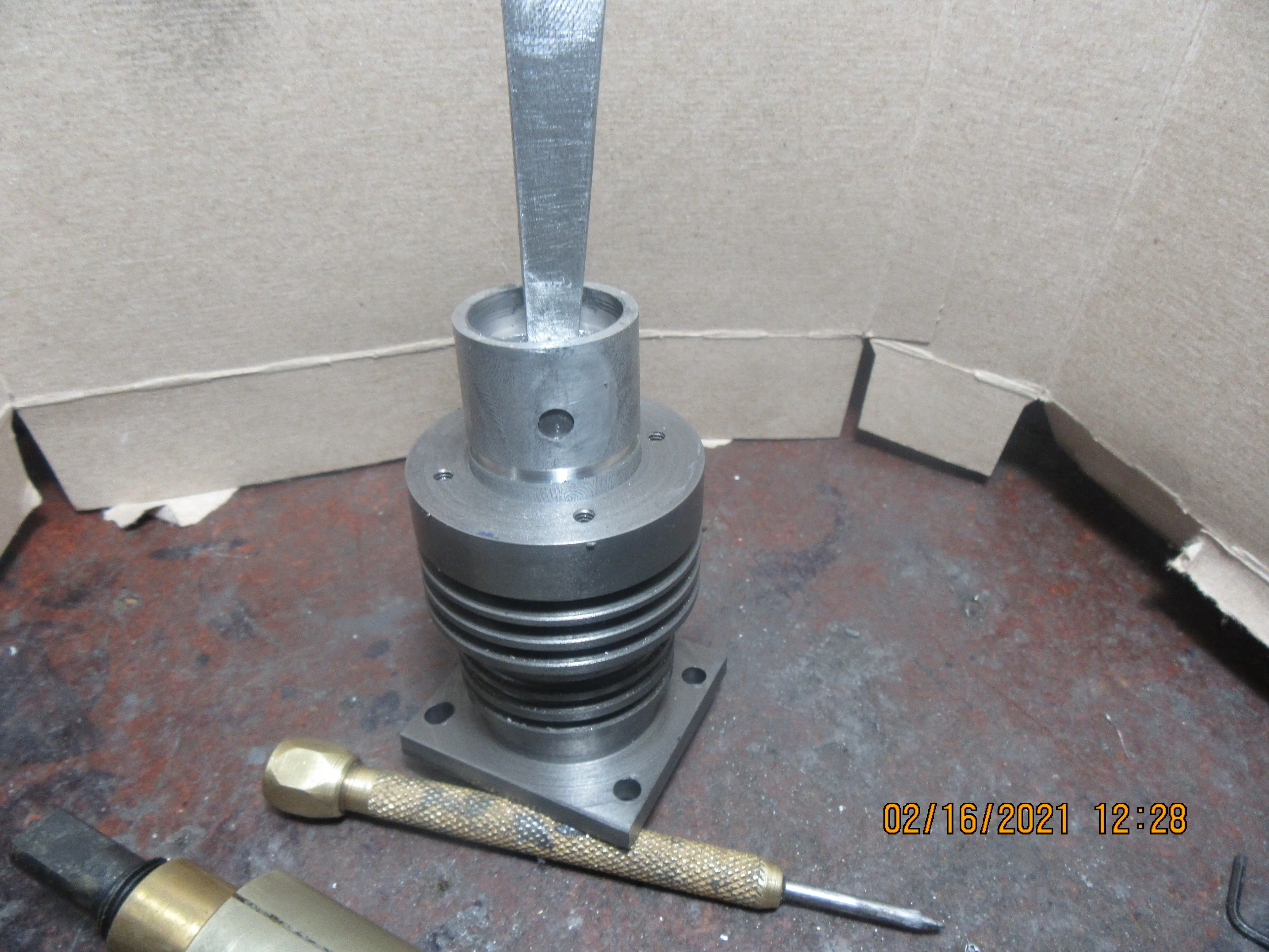
Why is the skirt so thick?---I really don't know. That's made from an old piston drawing that I brought forward and used on this engine. I think I'll thin that skirt down tomorrow when I have it up on the rotary table.
4L9yRk.jpg
 
Bob, I thought a skirt was like security doors when the tradesman's entrance door is left open... The wind blows in...
I was told a definition of skirt by an older guy in the workshop many decades ago. - A skirt hides a multitude of sins, and provides easy access to the sinners! - But "politically correct" didn't exist back then.

But (for the un-initiated) on a piston the skirt does a lot of work:
  • It provides location to keep the rings square to the bore. It actually provides a bit of spring to cushion "oscillating" loads, so must be fatigue resistant. - It may even have splits to tune the "spring", for varying operating temperatures (fit to bore). Rings don't actually help align the piston - they float in the grooves, or rather the piston floats around them.
  • It is a sliding bearing surface that maintains the oil film upon which it floats. This surface may be reduced to small pads, that are 10~20 micron above the rest of the surface, which reduces the oil film under pressure in shear and therefore "friction"...
  • It conducts heat from the piston crown to cylinder walls to cool the crown (via the oil film)
  • It conducts heat to the oil (splash) to also help cool the piston crown.
  • It helps stiffen the location between the gudgeon pin bosses and the ring location
At Hepworth and Grandage I was told the "clever bits" of a piston are the skirt and ring-pack. The rest is simple mechanical support for thos 2 features. They had a lot of different studies and computer models of skirts to optimise the heat flow, stresses, stiffness, surface shape, etc. within the skirt design. There have been more designs of skirts than you can imagine, and the latest (in your car engine) are real "mini-skirts" - or "jock-flaps" - compared to the appearance of Brian's knee-length version. Yes, Brian, it needs to be reduced a lot. (I just don't know how to design it!).
Great job you are doing.
K2
 
Todays fun limit has been reached. We have a finished connecting rod. Sometimes I wish I had a media blaster to even out the finish on things I machine so they would show up better on camera. ah well, nobodies going to see it once it's installed in the engine. It is aluminum 6061 t6 material. I don't generally put bronze bushing shells in these con rods, as they never see heavy lugging loads and aren't run often enough to make a difference.
XGAoRt.jpg
.
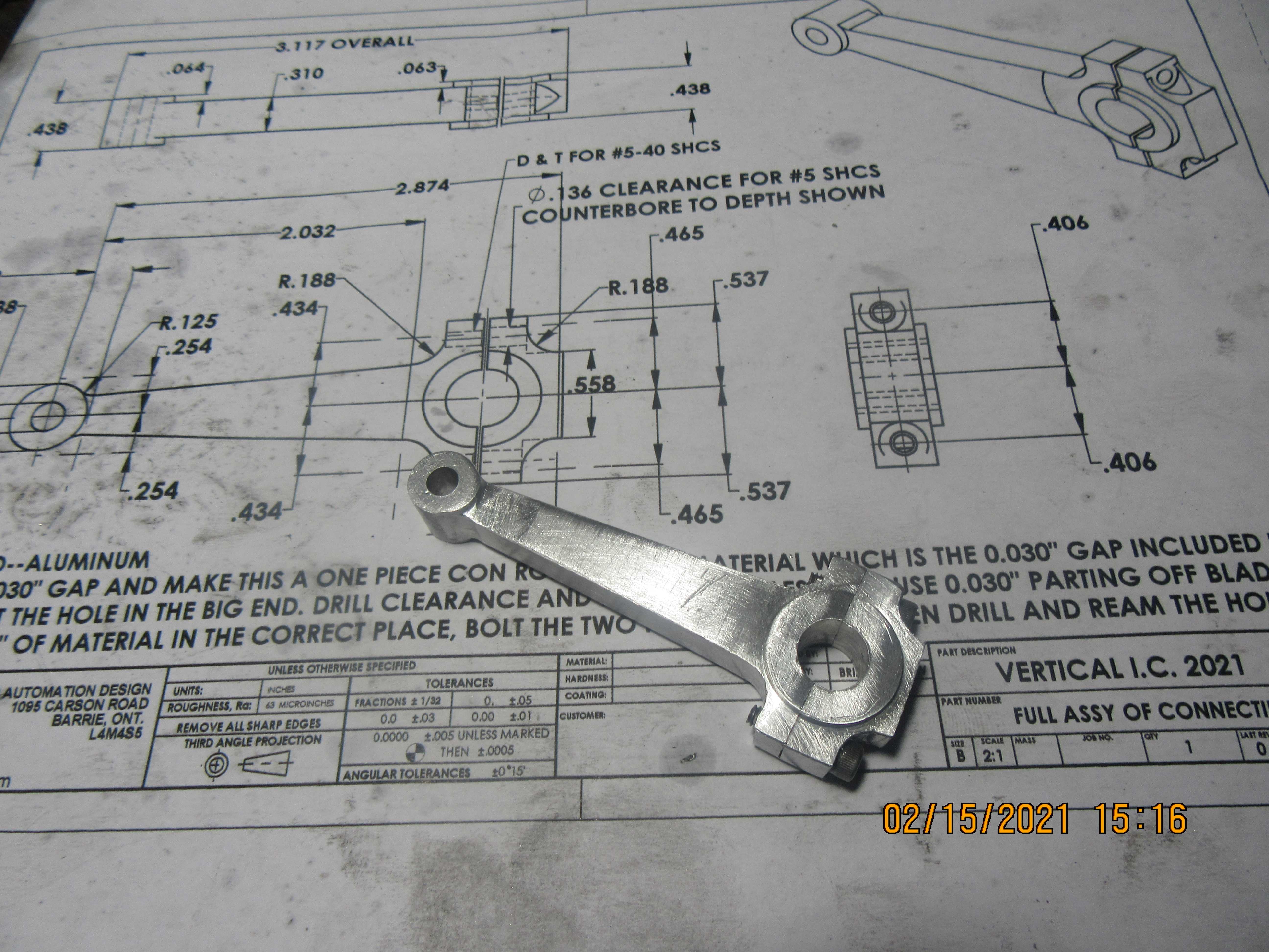
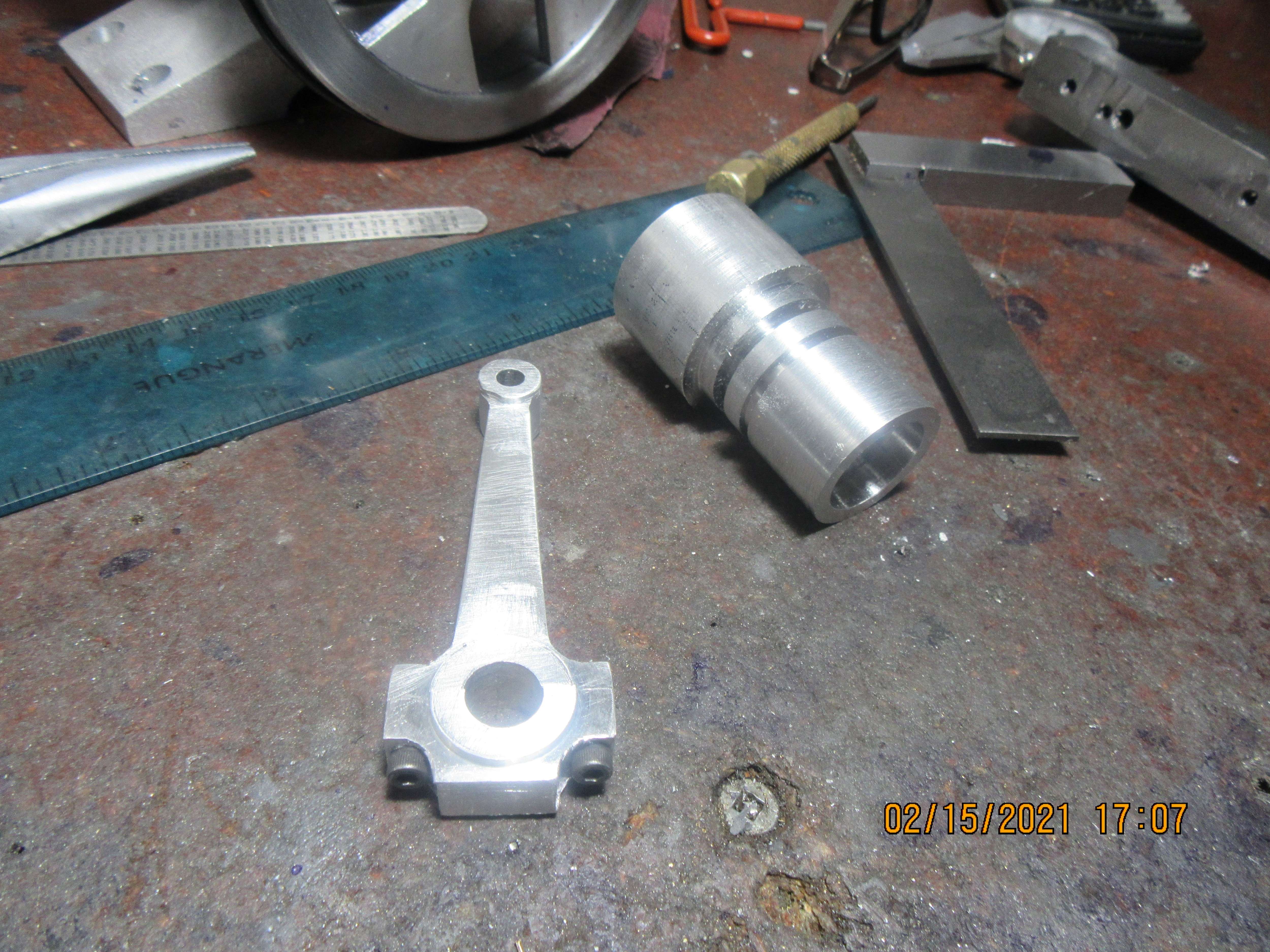
Brian, what is the size of the upper end hole / pin?
 
Awake---3/16" diameter.
This morning I lapped the cylinder with a 1" expanding lap using 400 grit lapping paste (you can just see a corner of it in the foreground.) until it was about 1.002 finished diameter. I had turned the piston to 1.003" diameter yesterday, An expanding lap will always leave a small "bell mouth" at the end of the cylinder, and it can work to your advantage. Once the piston would just start to go into the cylinder end, I mounted the cylinder in my 3 jaw chuck on the lathe, and using a handle I had made up to hold the inside of the piston, coated the piston liberally with 600 grit compound and slowly worked it into the cylinder with the lathe running at about 50 rpm. Once it would pass completely thru the cylinder I stopped and cleaned everything up with laquer thinners. The piston to cylinder fit is perfect.
bNIlqX.jpg
 
Hi Brian, In my humble experience (NOT having been a piston designer! - but I have handled a lot of pistons in the last 50 years...) - I feel the skirt "looks" thick. I don't know how to calculate the stiffness, heat flow, etc. to work out what is needed, but I do know that modern engines (since aluminium pistons became popular) try and reduce the mass at the pumping end... and on the swinging bits for that matter.
Also, (and again I don't understand the Engineering) the piston land above and between rings is always slightly reduced in diameter compared to the skirt so there is never any contact between that part of the piston and the cylinder. I guess only 0.001 smaller diameter than the skirt, but on a "race-tuned" 2-stroke reducing the top land by 0.001" eliminated the frequent seizures that had been occurring. I guess it may be to permit "crown expansion" due to the higher temperature at that end of the piston..... or something? - Or possibly something to do with the gases (Pressure) getting to the piston rings to affect the seal? I worked with a piston guy who explained the difficult time he was having trying to reduce the clearance at the piston crown so as to reduce the volume of unburned gases from that region that caused tailpipe emissions (not a problem for you engine! A lot of his problem was getting a big enough gap so the ring pack performed correctly (Gas pressure?), avoiding any contact at that part of the piston under extreme temperature differentials when warming up... (Pistons warm very quickly, cylinders slowly, so differential expansion can cause scuffing and seizures until cylinders reach optimum temperature) and reducing the volume of "cold" trapped gas that doesn't burn.

May not be an issue with your engine/operation....
Keep up the good work, still looking good!
K2
 
Sounds good to me... (but I'm not an expert, just an interfering old #$@%=÷€《!). It probably looks relatively thick compared to the diameter. (My wife says I look relatively thick all the time, compared to others...).
K2
 
Not a lot of machining done today, but some. I made up the fittings for the discharge end of the gas tank and got everything silver soldered or J.B. Welded together and cleaned up. Gas tank is now ready for paint. Gas tank, gear case, flywheel and rocker arms will be painted, and maybe the cooling fan. I haven't thought much about a color yet, but it will be a Tremclad color. Laying on the desk behind the engine is a piece of 1144 stress-proof steel I picked up today to become a one piece crankshaft, and a length of 1/2" brass round rod to make miscellaneous bits and bobs from.
LbGL5m.jpg
 
Look at the solid model. The exhaust system sets directly above the fan (see post #136). I know the fan is there, and I know not to stick my finger in it. I no longer have to deal with "Safety Committees". They were the bane of my existence!!!
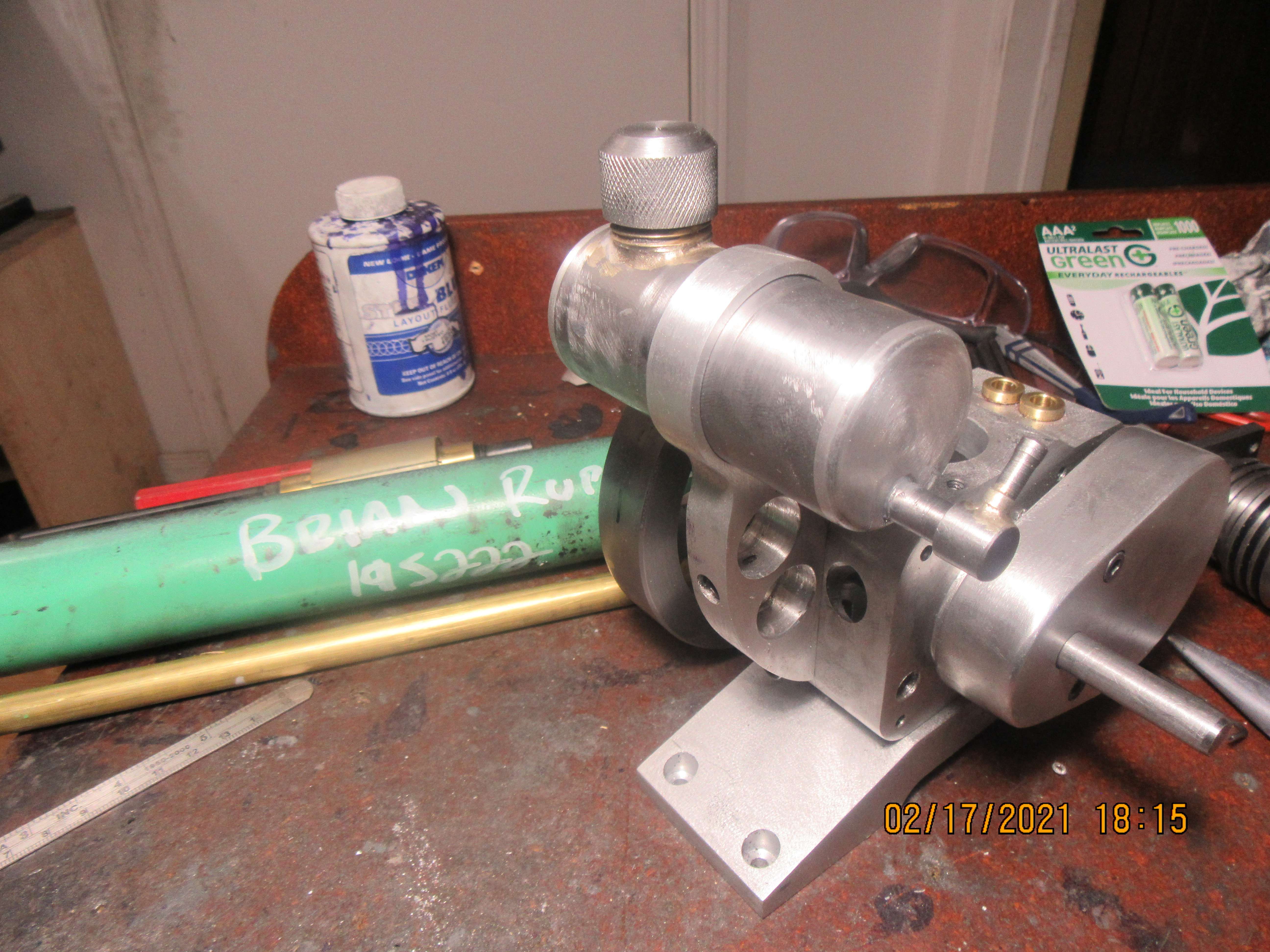
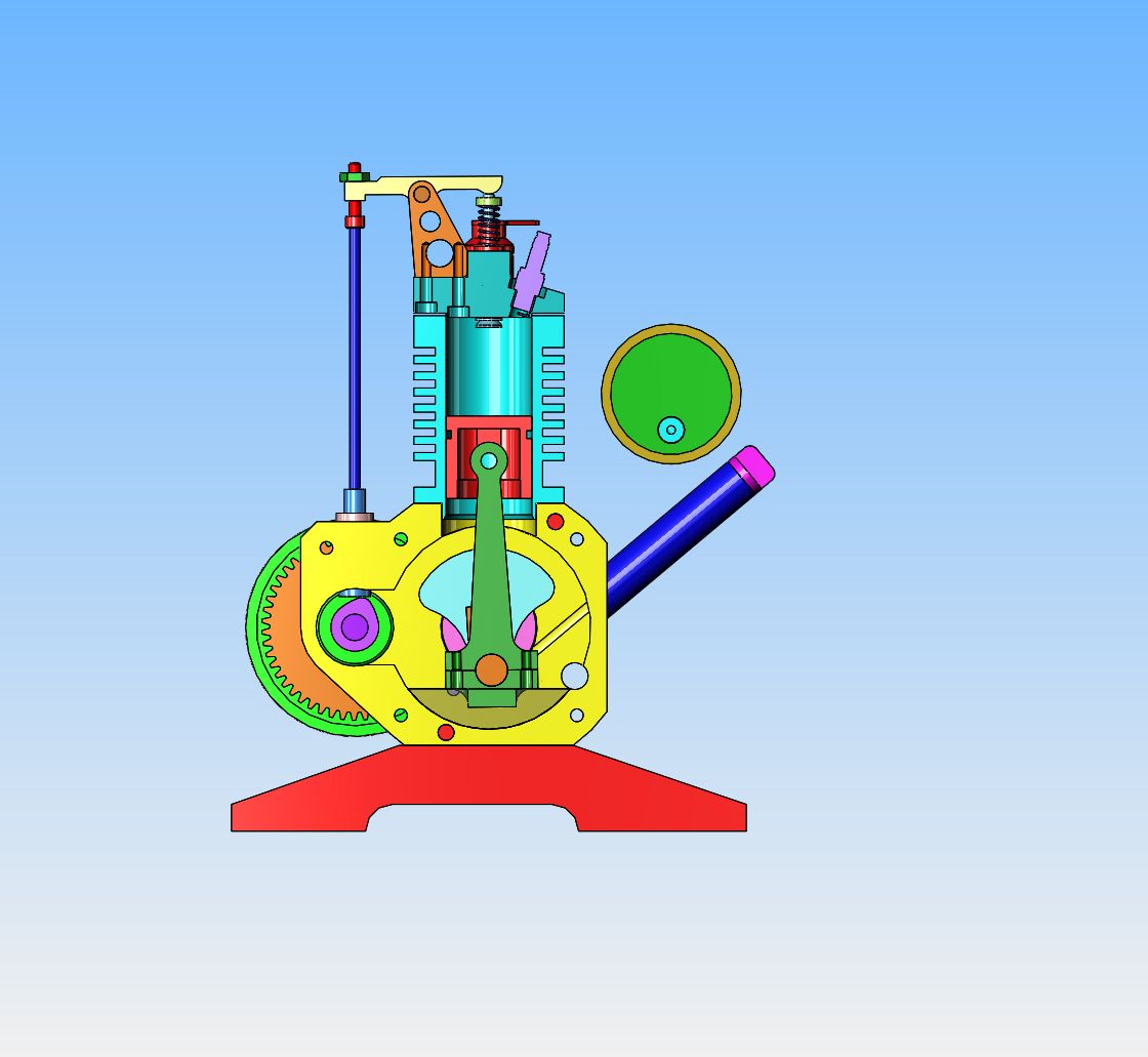
Ya........safety guy almost got me killed in a steel mill a couple of times........absolute morons......usally appointed by plant managers Bad subject with me too!
 
And at the closing of the day---We have two valve cages and two valves. The valves haven't been separated from their parent material yet, as I will use that for a "handle" when lapping the valves into their seats in the valve cages. The valve cages will get a hole thru the side, but won't be drilled until after they are Loctited into the cylinder head. That way I can drill the cylinder head and the valve cage at the same time. The cages will get the valve seat cut into them after they have been loctited into the head. In an earlier post I mentioned that I had picked up a weird size endmill. The maximum diameter of the valve cages is 0.375" diameter. They are sunk into a counterbore in the cylinder head. A 0.375" counterbore would have been too small, and a .438" counterbore would be too big. My "weird size" counterbore is 0.406" diameter, which should be "just right".(Makes me think of Goldilocks and the three bears).
9THfOQ.jpg
 
Today I used my odd size endmill and put the counterbores for the valve cages into the cylinder head. The cages were coated with #638 Loctite and then pushed into place. You can't really call it a press fit, because if it was a press fit the brass cages would collapse. It's more of a "perfect sliding fit". I will wait 24 hours for the Loctite to cure, then drill inlet and exhaust ports thru the cylinder head and the valve cages at the same time. Then I will lap the valves into the seats. I also made the timing adjustment handle today. I took a quick look thru all my available compression springs to see if any of them would work as valve springs, but I haven't made up my mind yet. Also made the adapter for the Traxxas carb but forgot to include it in the picture. I attached the gas tank into it's snazzy support using J.B. Weld. I'm running out of small things to make. Still have the cams and the crankshaft to machine. The cams and lifters will be made from 01 steel and flame hardened.
zrRS6G.jpg
 
Hi Brian, Sounds like the weird end mill may be an imperial sized 10mm? (approx 0.040" to the 1mm. = makes it a 10mm tool bit I think?). Someone told me decades ago, that a lot of engine makers (and others) "copied" ideas from each other. The 26tpi cycle thread was an imperial copy of the metric 1mm thread pitch, a 3 and lots of 64ths inch piston in many cars and motorcycle engines was actually the nearest to 80mm.. etc. When you consider the influx of "continental European" immigrants (Dutch, Swedish, French, Italian, Spanish, German, etc.) into the USA after 1800, it is hardly surprising that may who knew metric sizes (not feet and inches) made things "the same size as at home" - but converted them to the USA National inch sizes. Even "us Brits" have used ccs for engine displacement since Henry Ford was a tiny lad! - Perhaps being a bit closer to the technical pioneers of Messrs Otto and Carnot - and Renault (Of course!)?
 
Back
Top