Potty Simpson and Shipton Short Stroke Engine

Home Model Engine Machinist Forum

Help Support Home Model Engine Machinist Forum:

This site may earn a commission from merchant affiliate links, including eBay, Amazon, and others.
It's fun to follow your posts, Stew. Love seeing pictures of your progress and techniques.

Chuck
 
Cheers Jerry/Jim and Chuck

Got the eccentric finished off today

With a bit of bar in the lathe face and turn OD, then with a parting blade turn the 20mm dia * 5mm groove for the strap.

131_1478.jpg


Tranfer the chuck over onto the mill centre it under the spindle and off set 3.2 and centre drill.

131_1480.jpg


Back onto the lathe this time with a independant four jaw chuck and with a wobble bar clock the centre true

131_1482.jpg


Then drill and ream 8mm and turn the boss down.

131_1484.jpg


In the three jaw chuck and part off.

Drill and tap M3 for a retaining grub screw

131_1485.jpg


Job done

Time for a lose assembly of the parts made so far.

131_1486.jpg


131_1489.jpg


It looks more like a knitting machine than an engine, i wouldn't be suprized if it knitted me a pair of socks when it starts up, would any one like to place an order for a pair


Stew


Excellent work Stew. That is sure one interesting looking engine. ;D ;D

This is one I really want to see run. Not that I don't want to see them all run,but this one is, I don't know, just so different. I hope you put the perspex on one side so it can be seen.


Ron
 
Stew---You do amazing work. I am always impressed by your posts and your machining ability. I'm watching this develop, and admiring it all the way.----Brian
 
I'll have a pair Stew. Nothing fancy, plain black with a red pinstripe will do.

Jerry
 
Thanks Guys

Ron The Perspex safely stored away ;)

Jerry:- Order is accepted :big:

Stew
 
Things slowed down durring the past week while a did a little commission work ;D

Started on the base, first I squared it up to size, then drilled and tapped the cylinder fixing holes for M3 studs.

131_1503.jpg


This was so I could set the cylinder down and get some idea of whare the cut outs were to go and how much to cut out.

Then marked them out with the height gauge centred popped the lines and hatched them out some, so I didn't get mixed up.

131_1512.jpg


Then drilled the coners of the cut out first.

131_1513.jpg


Then chewed them out with a slot drill.

131_1515.jpg


Quick look see

131_1517.jpg


Now on with the columns, I'm fabricating these out of ally bar, for the fluted column I'm using 9/16" bar, first cut the bar down into handy lengths than face and centre drill one end. In the spin indexer with a 1/4" ball nosed cutter mill the 12 flutes.

131_1525.jpg


This is whare the power feed on the mill pays for its self, whist it was doing its thing, I fired up the lathe, and parted off the bases from some 20mm square ally bar.

131_1519.jpg


I'd have got these roosters finished today but my boss dragged me out of the shop to go the Docs for some injections for our visit to Africa. :- Now got a sore arm :(

Stew

 
As these parts will have a delicate edge that will be easily damaged by the chuck jaws I made a split collet, to hold them.

131_1535.jpg


Using the split collet part the flutted collumns off to length.

131_1533.jpg


Then as its important that the collumns are all the same length I fitted my back stop into the spindle nose, this is it with a few of the interchangable ends i've made for it.

131_1536.jpg


Then using the back stop face, drill and tap M3, I though I had a picture of this but no.

Here they are done they are all within 0.05mm

131_1539.jpg


Again using the back stop face off the square bit so they are all the same thickness

Got a pic of this :D

131_1547.jpg


Her they are with the columns

131_1549.jpg


Stew
 
It's looking good, I am still following and learning.

Jim
 
Thanks Guys

Bit more done on the engine the pillar parts was more about mass production than anything, made the roundels from 20mm brass bar, i'm going to paint the columns mat black and leave the roundels shiny brass :D

Used a form tool to form the rads drill and parted off

131_1554.jpg


Sorry about the crap pic.

Then with the back stop faced them all off the same.

131_1555.jpg


Then turned up a mandrell a blended things in and gave them a polish.

131_1558.jpg


This is how one looks like.

131_1561.jpg


And time for an interest boosting assembly.

131_1564.jpg


Not looking too bad.

Stew
 
looking great Stew :bow:
Pete
 
Thanks Pete

Its bin a good day in the shop finished off the fly wheel.

In the independant four jaw true it up so the inside of the rim is running true, then clean up the hub and the inside of the rim, face and turn a register on the OD.

131_1565.jpg


Turn it round clock up the register true, and clean up as for the first side.

Then griping on the inside of the wheel clock the register true and clean up the OD, and drill and ream 8mm

131_1566.jpg


Job Done

131_1569.jpg


Stew

 
Stew, is that an RDG casting or Stuarts?
 
Jason

Its an RDG Casting,

Quality quite good, not to much flash and running resonably true only needed a couple of mill skimming off it. It had one hard spot on the rim from a chilled flash, but that came off OK with a TC tip tool.

Stew
 
sbwhart said:
Thanks Guys

Bit more done on the engine the pillar parts was more about mass production than anything, made the roundels from 20mm brass bar, i'm going to paint the columns mat black and leave the roundels shiny brass :D

Used a form tool to form the rads drill and parted off


This is how one looks like.

131_1561.jpg


And time for an interest boosting assembly.

131_1564.jpg


Not looking too bad.

Stew

Stew do you make wedding cakes?? :big: :big:

Peter ;D
 
steamer said:
RDG as in RDG tool?

Dave

Yes Dave Her's the link http://www.rdgtools.co.uk/acatalog/Fly_wheel_Casting_.html to the fly wheel page they do a range of different sizes i used their 7" for my Over Crank Engine fly wheel' quite happy with the quality and price is not bad either.

Wedding cake :big: :big: :big: it did remind me of something but I couldn't quite put my finger on it I recon your spot on with that one Peter.

Stew
 
For the price the RDG ones are quite good, I've just done one of the 10" ones and apart from a small hole in the hub that can easily be filled it was very good. I did sort through them at a show and that was the third one down the pile the others having small faults in the rim.

PICT0345.jpg


J
 
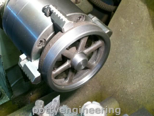
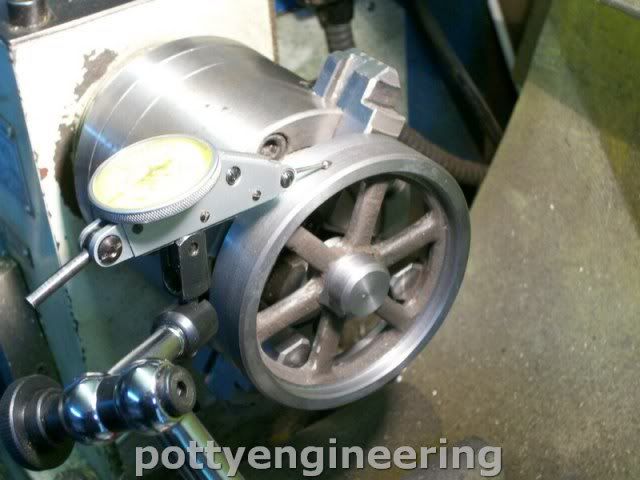
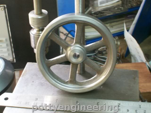
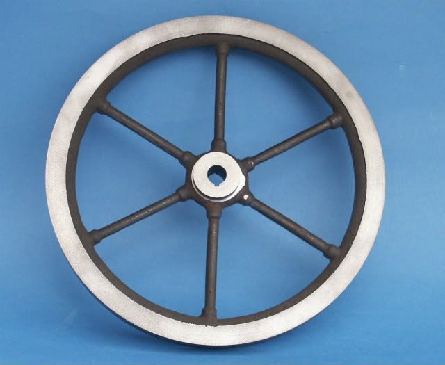
Fine looking fly wheel their Jason.

Things have been real slow on this build over the last week due to domestic duties.

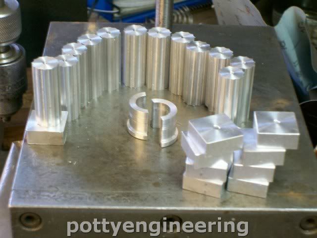
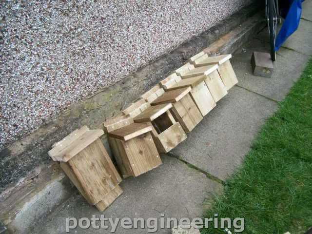
One of those duties was solving the aviane housing problem in Glasgow where our son is moving into a new/old house, with a big garden, he asked if i could make him some bird nest boxes, yes I said, he proptly ran through a list of boxes with diferent hole sizes, and shapes, plus a box for Bats and a block of flats for sparrows.

This is the score minus the sparrow tower I ran out of wood for that, which I will buy at B and Q on their old git discount day.

131_1570.jpg


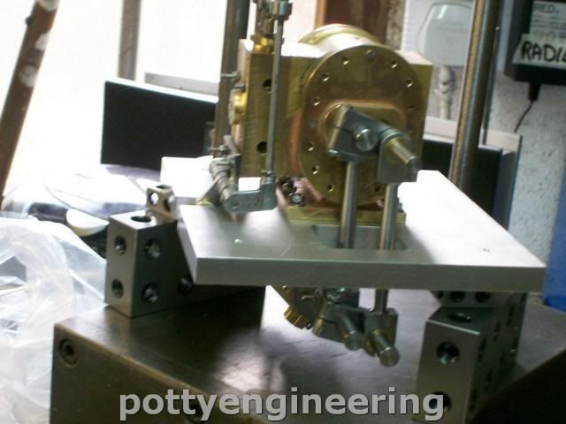
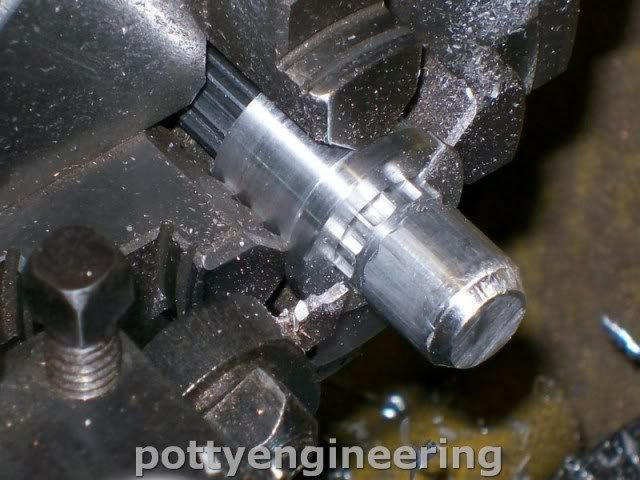
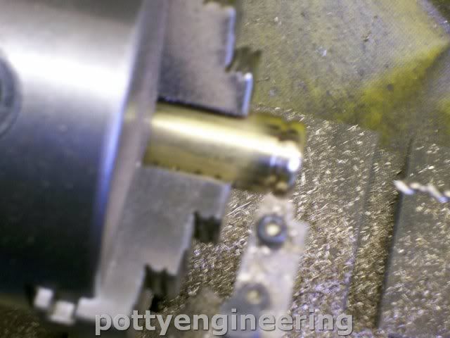
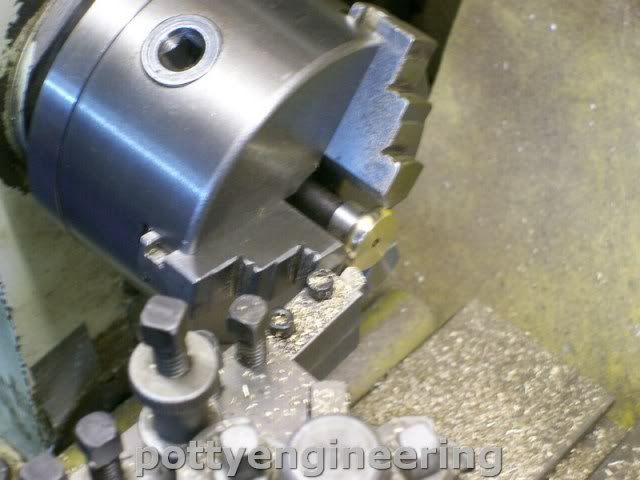
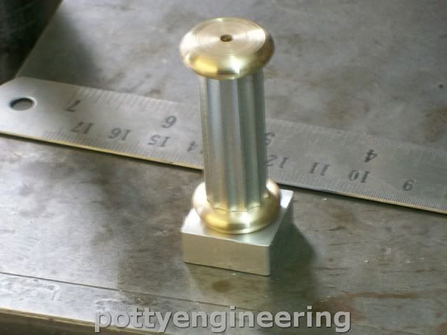
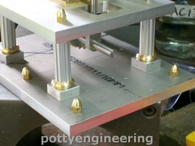
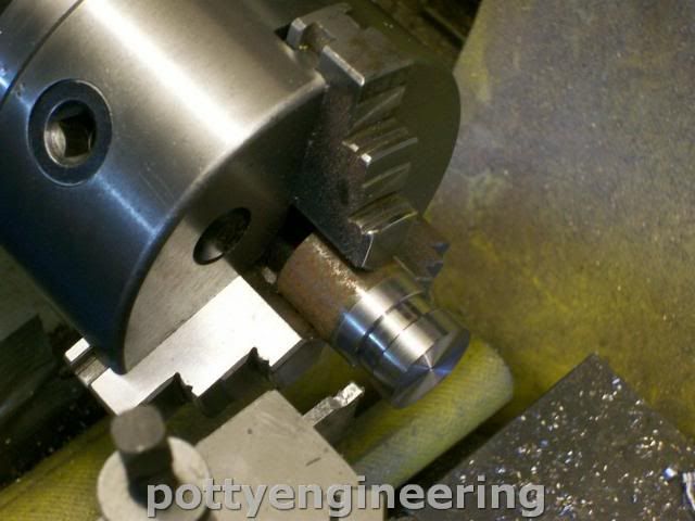
Made some acorn nuts for the engine, ground a form tool up to form the dome.

131_1573.jpg


This how they look on the engine.

131_1576.jpg


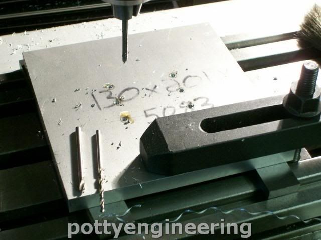
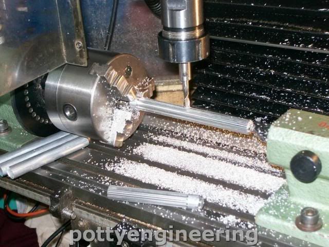
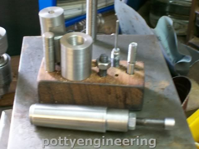
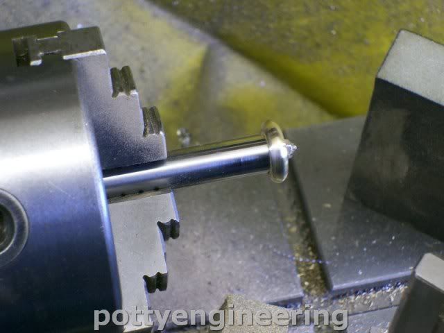
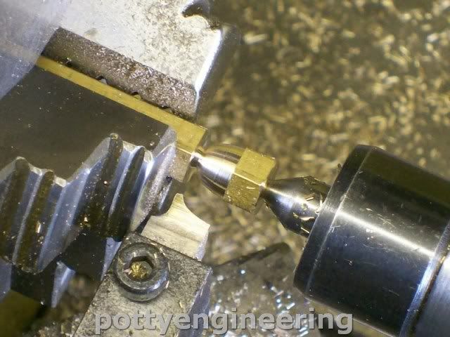
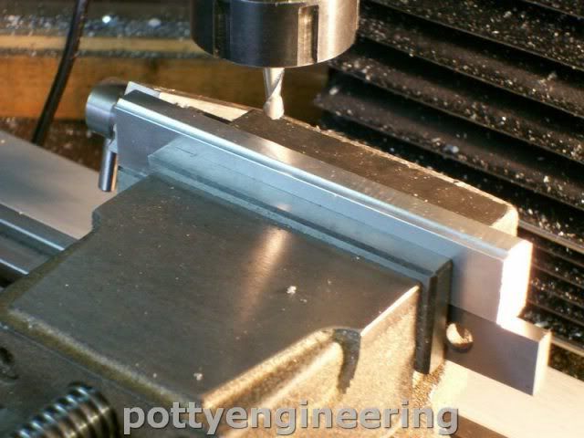
Then made a start on the bearing housing, I'm going to try and emulate Jason, and Ramon's method using JB weld. First square up to size a chunk of ally, then run a 3mm rad down each edge.

131_1579.jpg


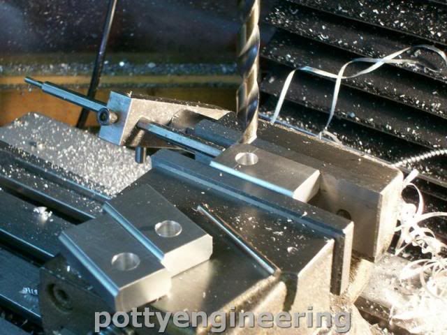
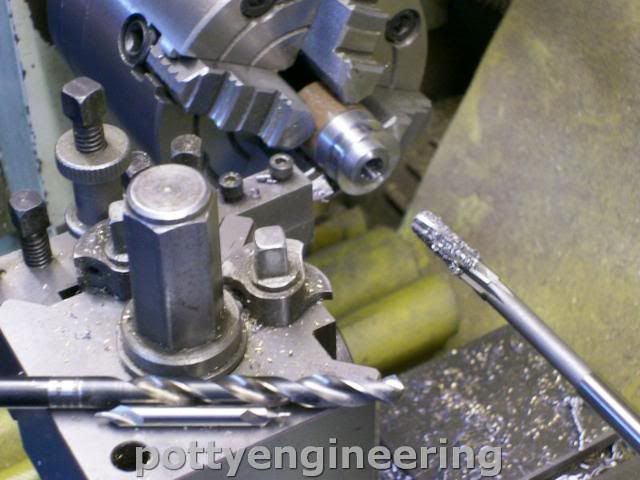
Cut off and skim them off to all the same length, then rough drill the hole for the bearing.

131_1581.jpg


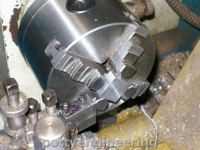
Drill through M2.5 tapping.

131_1582.jpg


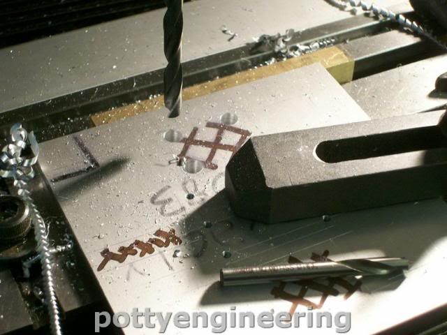
Her desaster struck :doh: I broke the drill and failed to get it out, tried nocking it out from the other side it moved a bit then i got the punch stuck, so gave it up as a bad job I'll just have to make another, in fact this may not be a bad thing as the flywheel bearing could do with being a bit wider.

131_1584.jpg


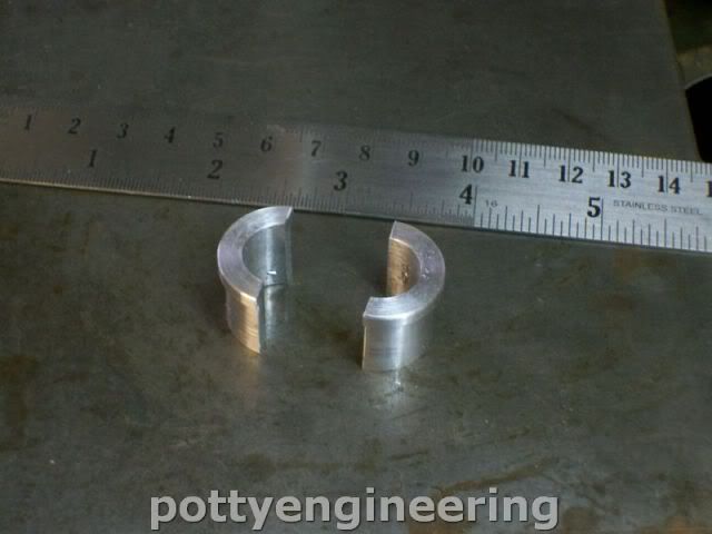
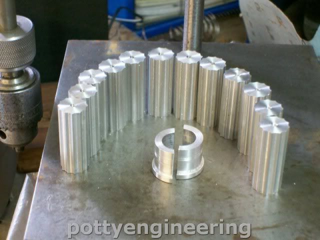
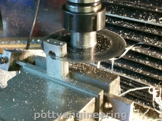
Cut the caps off with a slitting saw.

131_1585.jpg


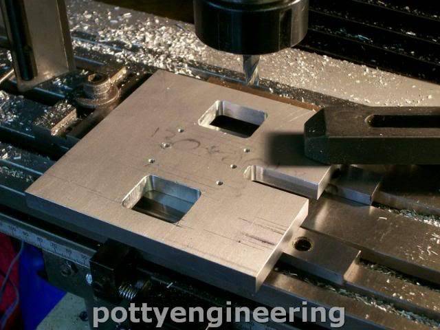
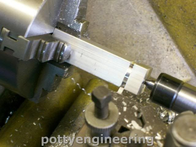
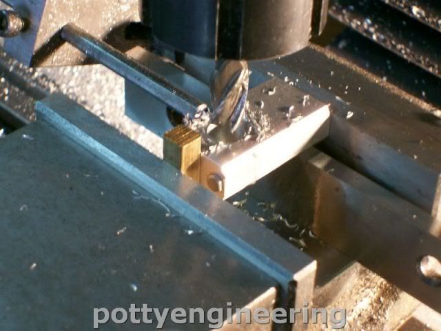
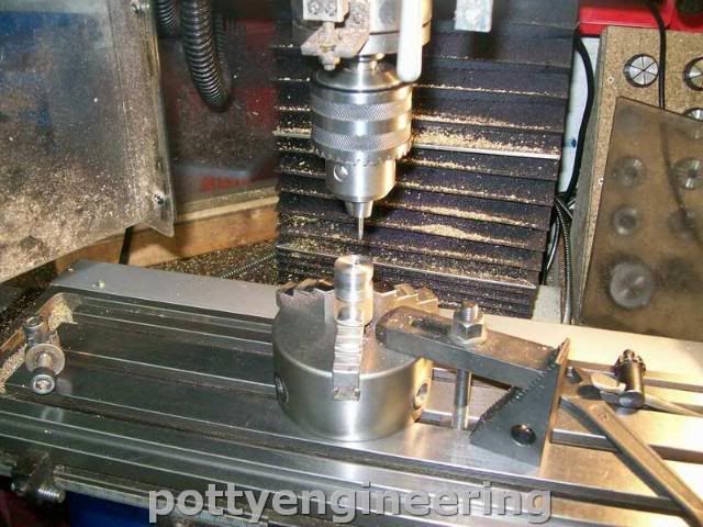
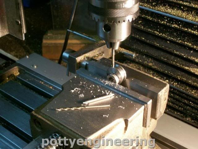
Tap M2.5 and bolt them together, and then giving the scrws a bit of support pass a 11mm end mill vertically down through to form the bearing bed.

131_1588.jpg


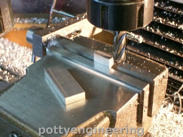
Now for the bases as before clean up and square the ally to size, cut them off and mill to the same length.

131_1589.jpg


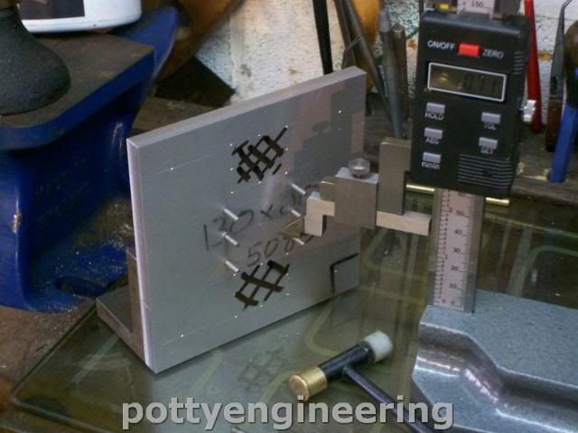
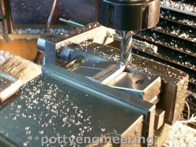
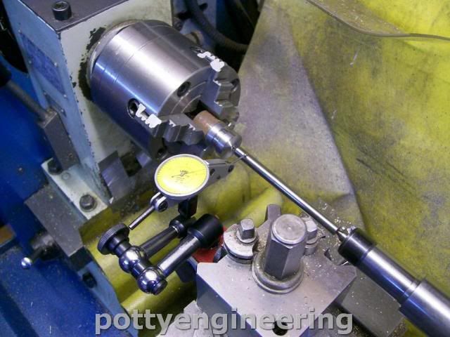
Then using the sine bar angle the edge of the base.

131_1590.jpg


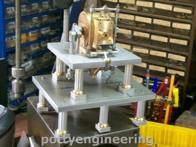
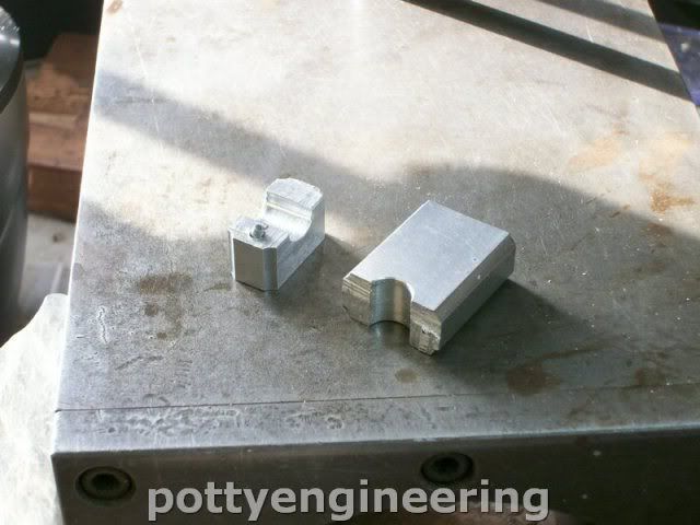
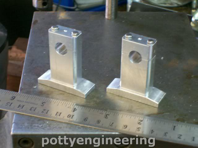
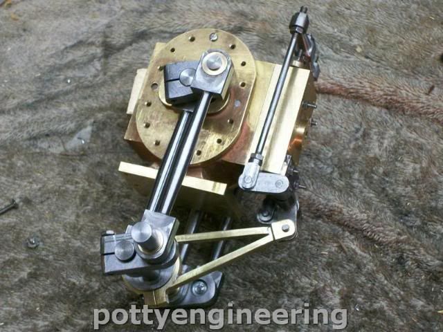
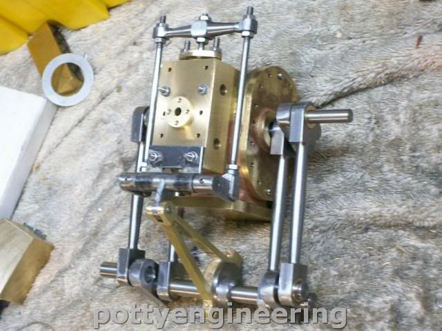
This is what they look like so far, the main bits needs sortening to get the centre height so they will look more in proportion.

131_1594.jpg


The next couple of weeks will be slow weeks as well which is a bit frustrating as there isn't that much to do to the engine.

Stew
 

Latest posts

Back
Top