An experimental engine

Home Model Engine Machinist Forum

Help Support Home Model Engine Machinist Forum:

This site may earn a commission from merchant affiliate links, including eBay, Amazon, and others.
Arnold,
Re earlier superglue failure. Here's a tip.

All metals oxidise virtually instantaneously - so you are bonded to the "rust" not the bare metal.

Try sanding the surface using the glue as lubricant (fine with epoxies - a bit more problematic with superglue - but doable) this causes the glue to bond directly to the metal surface.

Wipe clean to get rid of debris - do not wipe off glue film.

Do this to both surfaces and proceed as per normal.

To be sure etching primers do the same thing - but if you don't have any to hand .........

Strength is 2 to 5 times better.

Ken
 
Thanks for that tip Ken Thm:

This project has been waylaid a bit; I wanted to be much further along but the redesign and personal life interfered.
Re-designing the valve gear layout took quite a bit of time, but I think I'm close enough to continue now.

Today's bit - a start on the frames...

As the loco will be a bit on the narrow side, I want the frames to be fairly heavy to keep the center of gravity as low as possible. I decided on using 3mm thick steel plate for the sides, and will use mild steel for the cross beams as well. The only 3mm plate I have is locked up in a fairly big sheet, and cutting a strip off it was a bit of a challenge. I could have tried man-handling it on the band saw, but that was just asking for a broken blade. Another option was using one of my angle grinders, but I don't like cutting thinnish plate with either of them; it takes a lot of concentration and makes a hell of a noise. Gas is a bit expensive, so I tend not to use my oxy-butane kit for that. So, I settled on the venerable jig saw with a suitable fine HSS blade for cutting thin steel:
normal_IMG_2226.JPG


Next I sawed of two suitable lengths from the strip and off to the drill press with a rubber-backed sanding pad mounted in it. After a bit of work, most of the rust and crud was gone from the plates:
normal_IMG_2227.JPG


A bit of clean-up followed on the mill; very carefully over the extended bits with a fine feed:
normal_IMG_2228.JPG


Once I had both long sides parallel and to width, I squared up one reference edge as well:
normal_IMG_2229.JPG


Then I drilled holes for the cylinder mountings, axle bushes and valve gear mountings/bushes:
normal_IMG_2230.JPG


Some holes followed for mounting the cross beams, and I finally split the two sides apart, de-burred and left off for the day:
normal_IMG_2231.JPG

There's still some more work to do on the frames, but at a later point.

Regards, Arnold
 
Some more progress... eventually :big:

Started off with the axle bushes. I'm out of my preferred phosphor bronze in the smaller size, so I used 7mm brass rod to make them. The first one took a bit of time to get the final sizes I needed, but then I just jotted down the cross slide readings and used that for the next 5 - which went quickly. Here I'm on the first one, with the final parting done to just below the 4.9mm diameter that it will be drilled out to:
normal_IMG_2234.JPG

Then a quick spot with the center drill, and drill out to 4.9mm, and the bush ends up on the drill bit. I find this more convenient to do than to first drill and then part off.

A little while later, I had all 6:
normal_IMG_2235.JPG

On one, I took the parting too deep... So it left quite a burr, but the 5mm reamer will easily take care of that later.
These were then pressed into the frames together with bearing retainer to make doubly sure they'd stay put, and set aside to cure a bit.

A block of hot-rolled flat bar was cleaned up, and accurately machined to make the frame spacer pieces from:
normal_IMG_2236.JPG


Some more machining and a little tapping later, I had the two spacers:
normal_IMG_2237.JPG

I actually made holes in the frames for a third spacer toward the middle, but things seem entirely rigid enough with just the two.

The first real "feel" of the frames coming together:
normal_IMG_2238.JPG


I then reamed the axle bushes out to 5mm with a hand reamer, running it through both bushes completely to ensure alignment:
normal_IMG_2239.JPG


Further work on the cylinders will be easier if they are split apart at this point, and I wanted to see how they fit on the outsides of the frames, so I slit them apart:
normal_IMG_2240.JPG

The bottom cylinder is not getting clamped on the studs; I shoved a T-piece between the studs so the vise could clamp down through it on the valve cover plate.

With the cylinders fit to the frames, I did a quick mock-up to see if things will look OK. The frame is resting on some blocks on the track at about the height it will be once the wheels are fit to the chassis, and the aluminium stock lying on top is approximately the same size and in the same position the boiler will go after getting some cladding added to it:
normal_IMG_2246.JPG


Some more size comparison with Fred:
normal_IMG_2248.JPG


Things look about right to me ;D

This boiler would definitely be too big:
normal_IMG_2249.JPG


Not as much progress as I'd hoped for up to this point, but some is better than none!

Regards, Arnold
 
;D Managed to squeeze an hour in the shop after work today.

Skimmed off a bit of hot-rolled bar to 30mm diameter:
normal_IMG_2252.JPG


I then drilled a 4.5mm hole deep enough into it to allow for 6 wheels and parting space.
Then, with the QC toolbit swung over to the correct angle for the flange, the first wheel rim was turned down to 28mm, and a note taken of the cross slide reading to get the others to exactly the same size. Then I started parting off the first wheel:
normal_IMG_2253.JPG


The others soon followed - two of them "blind" - i.e. without wheel flanges; these will become the center wheels; I found that it is relatively common in this size of locomotive to do this, as it allows locos to negotiate tighter curves. The six wheel blanks awaiting further machining:
normal_IMG_2254.JPG


Regards, Arnold
 
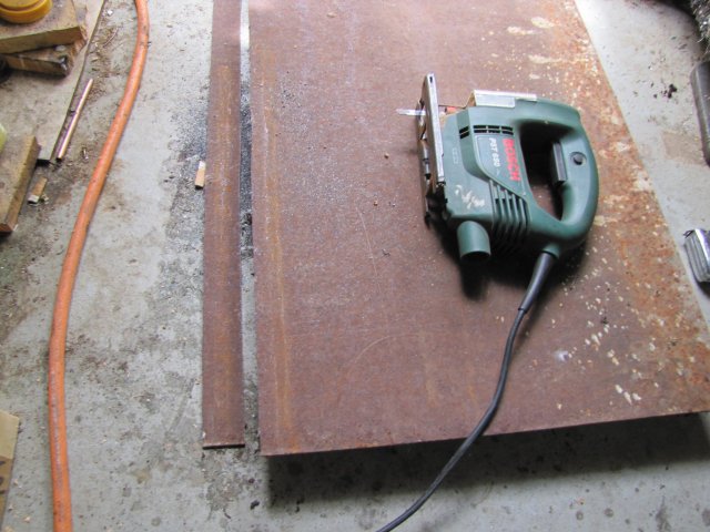
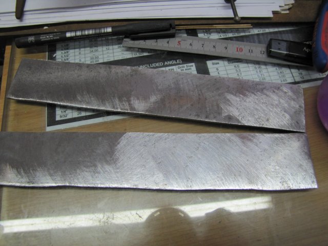
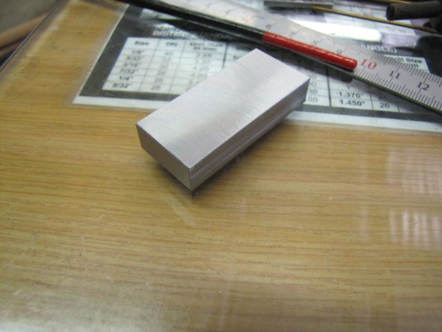
Today was a bit slow in the shop, and in retrospect things could have gone a lot better had I thought things through a bit more.

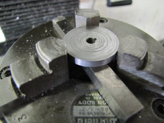
Finding a suitable method for mounting the wheels to the shafts proved to be a bit daunting. There's not much space anywhere to fit grub screws, and I couldn't have bits sticking out. As I want to be able to easily disassemble and reassemble things, retaining compounds is not an option either at this point... I settled on using round "keys" to locate the wheels on the axles and countersink screws to retain them; a lot of work initially, but would hopefully pay off in the short to medium term. There's an additional advantage; some machining operations on the wheels will be easier if they are keyed.

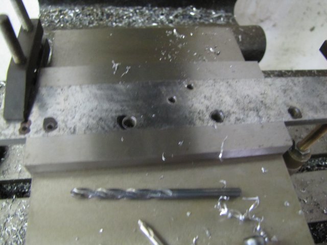
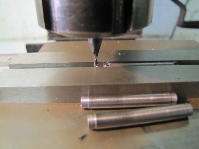
The 5mm shafts would have 4.5mm steps turned on them to locate the wheels, and then a 3mm countersink screw used to retain the wheel on the shaft. A bit of 1.5mm wire would serve as the key. Fiddly work ::)

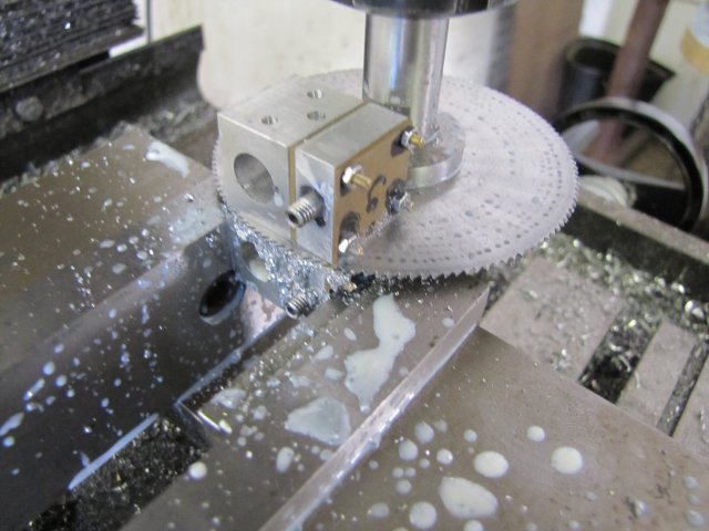
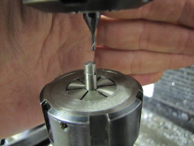
So first order of the day, start cutting key ways. I centered the rotary table on the mill, mounted the 3 jaw chuck with a wheel blank, dialled in a 2.25mm offset on X and chucked a 1.5mm 2 flute center cutting endmill:
normal_IMG_2255.JPG


Then just gently milled straight down to take out a half-moon. For the blind wheels, I just spaced them off the face of the chuck with a square toolbit, taking care that I would not run into it with the milling cutter. Here's the result:
normal_IMG_2256.JPG


In retrospect, I was silly with the following proceedings and should have used a different method that I used later after completing the wheel facings, but for the record...
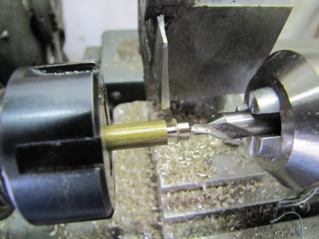
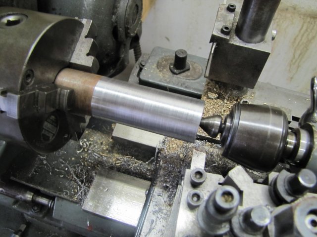
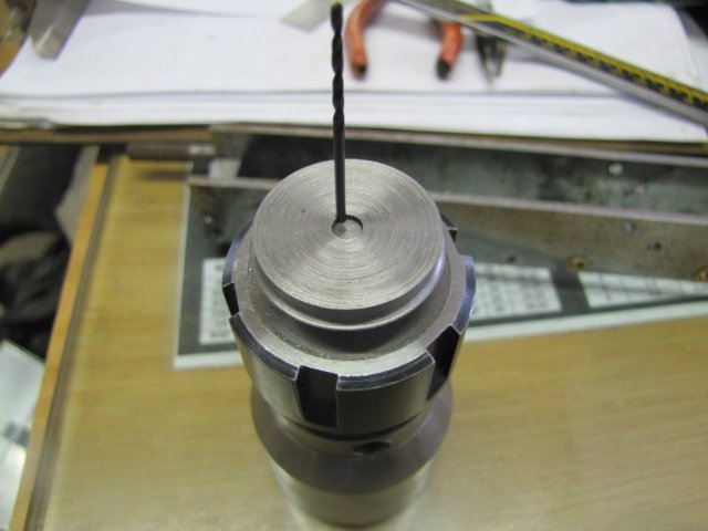
I chucked a bit of 5mm silver steel in the lathe's collet chuck, and turned it down to 4.5mm diameter for a length of 3.5mm; 0.5mm less than the final wheel thickness. Then moved the collet chuck to the rotary table on the mill. As I'd not changed any settings on the mill, and my chucks screw down pretty accurately on the chuck adapter on the R/T, I could just straight away mill a half moon in the arbour as well:
normal_IMG_2258.JPG

(had to keep my hand behind to take the photo; the camera wanted to focus everywhere except on the work ::)

A quick test with a wheel and a 1.5mm drill shank - and a very satisfactory fit:
normal_IMG_2259.JPG


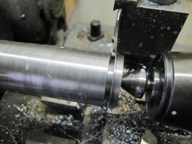
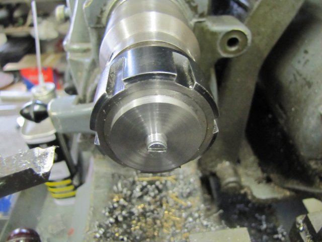
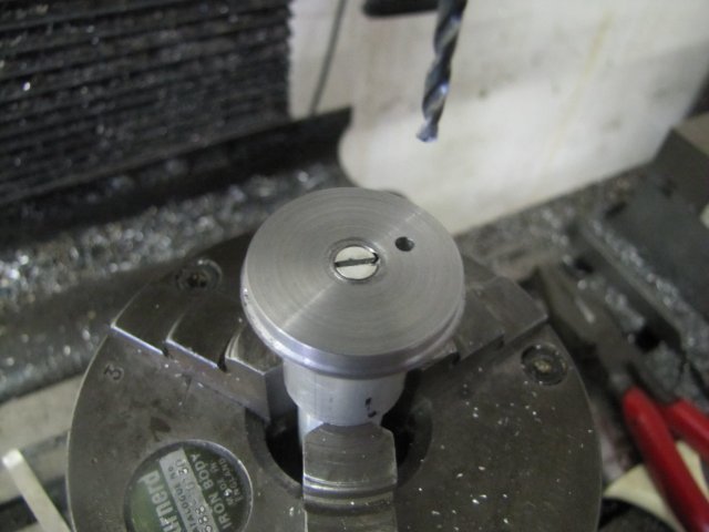
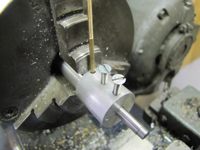
Back on the lathe with the collet chuck, center drilled the arbour, then drilled 2.5mm and threaded 3mm. Then I cracked the collet closer loose and pushed the arbour back into it so that a wheel mounted on it would be clamped against the chuck face by tightening the screw. I mounted the first wheel, with a short bit of 1.5mm wire shoved into the "key" bits, and a bit of offcut with a 3mm hole hole was used with a 3mm screw to clamp the first wheel down. I locked the carriage, and then faced the wheel to size using the topslide for infeed - taking note of the topslide and crosslide readings at final size:
normal_IMG_2260.JPG


For the following wheels, I just machined to the dial readings and things went well, except that it was difficult to get the wheels off the arbour after machining. I used my pocket knife to wedge them away from the face of the collet chuck ::). On the fourth wheel disaster struck; I overshot the cross feed grossly, the tool dug in and sheared the holding screw away; I heard it landing somewhere behind me in the shop.... Fortunately the wheel stay put and I managed to stop things before it went flying. Some choice, highly reserved and rarely used words in an astounding variety of international and native languages followed...

Recovery was a bit painstaking; there was just enough of a stub left of the screw to use a needle file to file a groove in it without disturbing the entire setup. I managed to get a screwdriver into the groove, and a bit of a turn; then more groove filing, and another bit of a turn. This went on for a bit, then I got the junior hacksaw to the groove with enough of a slot to unscrew the stub. Sorry; no photos; I was a bit peeved at that point :big:

With the stub out, I took a break and had a bit to eat and a good strong cup of coffee. Always make life seem better :D
Then I finished the rest of the wheels in the same way, though a bit less energetically. I must still have been a bit peeved off though; I didn't take any photos of using my tooling plate for the first time. To get rid of the bosses left on the wheels, and to get the correct countersinks in the hubs, I used the tooling plate with bits 'n bobs and disassembled toolmaker's clamps to clamp down the wheels to countersink the hubs. I'll do a mock-up of the setup tomorrow if I remember.

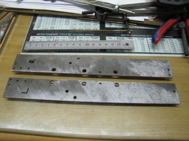
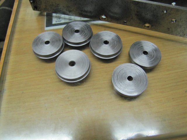
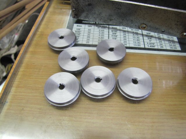
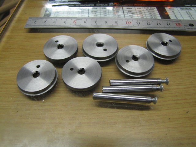
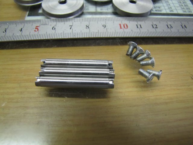
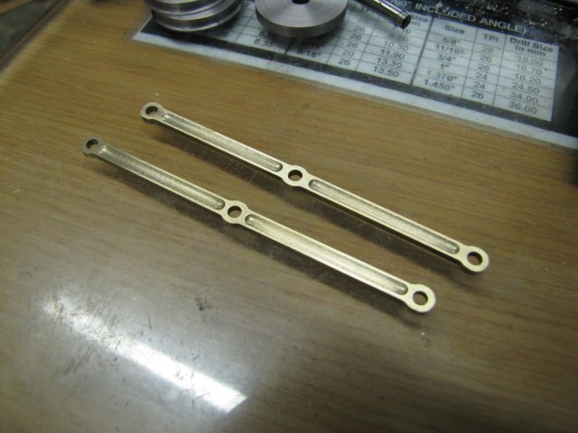
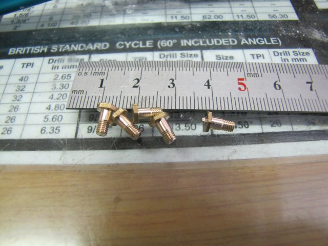
I ended up with this motley crew for all that effort; hardly what I have come to expect from myself, but will do for the experimental engine for now:
normal_IMG_2262.JPG

The wheel at the top left has a gouge around the hub; that's the one I had the "fun" with.

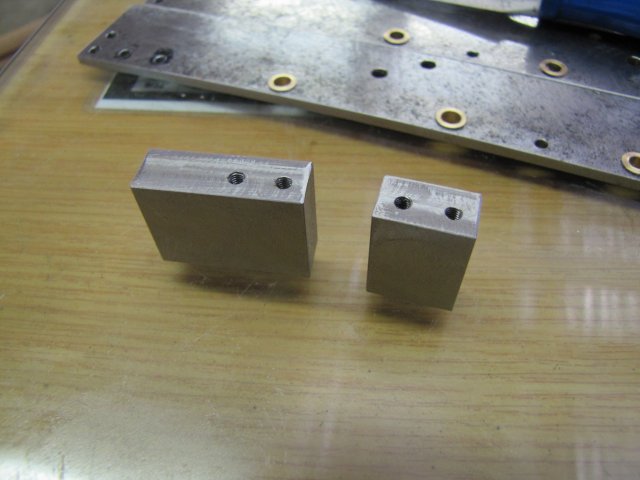
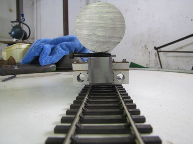
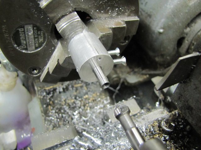
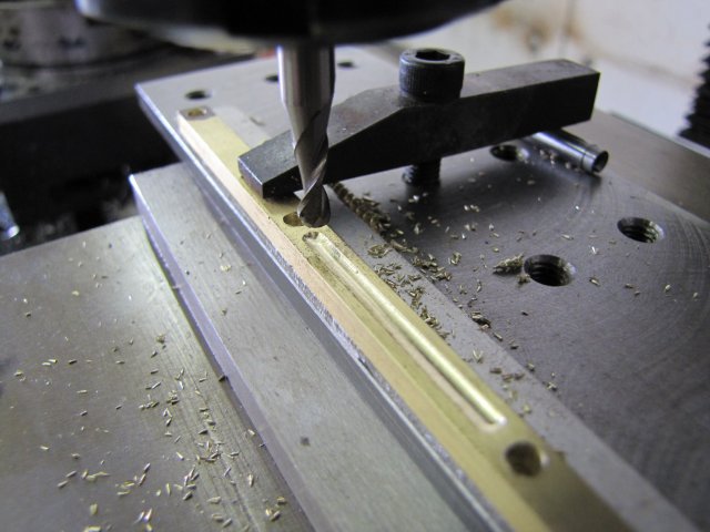
Now came part of the "in retrospect" moment :doh: - to drill for the crank pins on the wheels, I would need a new arbour. The one I made earlier would not work, as I could not drill the holes for the crank pins using it as-is, as I'd drill into my collet chuck or collet. Definite No-No. The scars you see on the lathe's 3-jaw was done in years-past, not by me, nor by its previous owner (as far as I'm aware). There are no machine marks on any of my chucks or vises that I put there - I take great care not to make any. The existing arbour would flex too much under off-center drilling pressure, so I made a new one from some aluminium that would offset the wheel; used the 3-jaw for that so that I could transfer between lathe and mill without re-chucking. I milled the key half-moon in it on the mill like before, but then drilled it out deeper, so I could shove a bit of wire in there and leave it in place. Much easier than having to fit individually for each wheel. A later photo will show more detail of the new arbour (there's a linky clicky thingy on the photo to load a bigger one)

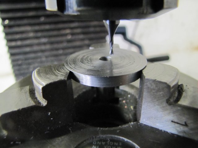
With the R/T on the mill still set up, I just added the additional offset to get the 7mm from center I need (for a 14mm stroke). The wheels were divided into a left and right hand set; 2 flanged and one blind in each. For the first set I turned the RT so that the "key" would be at 0 degrees, and drilled the crank holes (2.5mm to thread M3) - taking care to tighten down the wheels against the round key in the same (in this case clockwise) direction to eliminate any radial play:
normal_IMG_2263.JPG

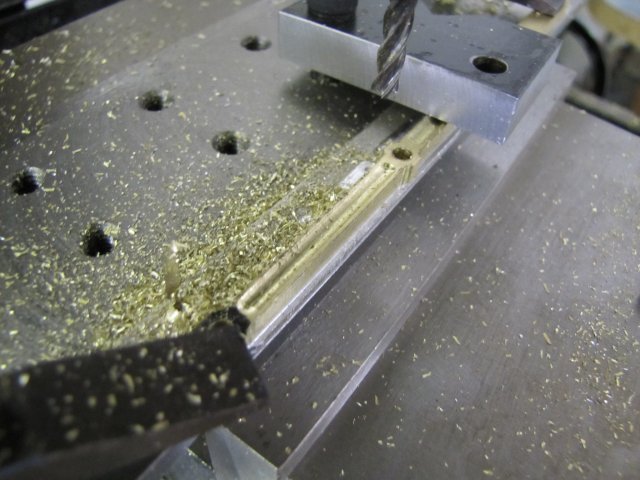
For the other set of wheels, I cranked the R/T around to 90 degrees, and followed the same procedure as for the first set of wheels. This will hopefully make life easier; the wheels will already be properly "quartered" if I cut the key ways in the axle shafts in line; which should be easy to do.

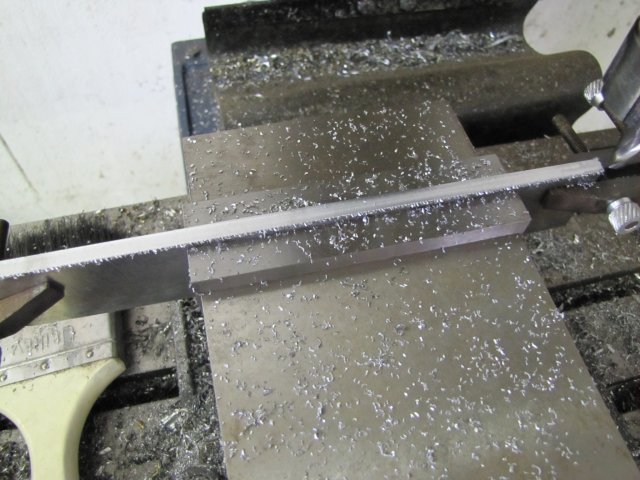
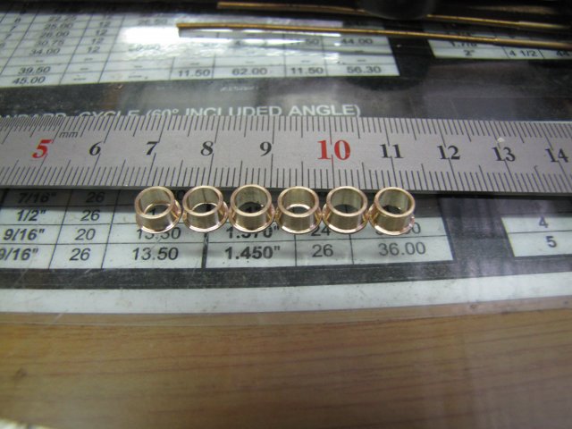
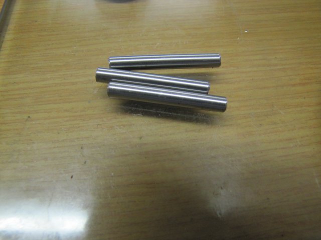
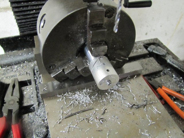
Then I started fiddling with more 5mm silver steel for the axles - roughly cut to length:
normal_IMG_2264.JPG


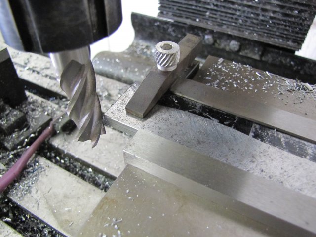
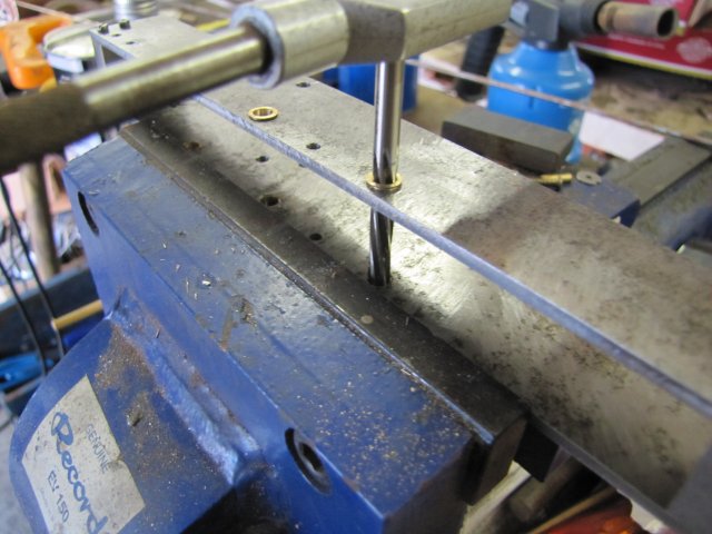
My 5mm ER collet for the lathe is out by about 0.02mm, and would make for wobbly wheels if I turned the shafts directly in it. Seeing as I already had a bit of aluminium (the last arbour) chucked in the 3-jaw with a near-accurate centered hole (except for the threads) - and as I would need a way to fairly accurately get the axles to the same size, I decided to just use it to make a once-off jig to hold the shafts for machining and to set their length. So I ended up pre-drilling holes to thread for grub screws to hold the axle. I don't know if what I did next is a good idea - seemed so at the time, and I can't think of any reason not to... I lightly clamped the lathe chuck in the mill vise and drilled the holes:

The above photo has the linky clicky thingy I mentioned earlier.

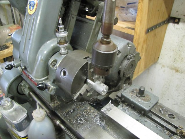
Back on the lathe with the chuck, I used somewhat unconventional means to tap the M3 holes in the ex-arbour and now jig; none of my tapping handles could reach, so I used and oldish and seldom-used lathe chuck to do it - being careful not to put any lateral loads on the taps:
normal_IMG_2266.JPG

Only the front two holes were tapped; the third is for inserting a bit of rod to set the depth of the shafts later on.

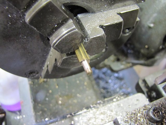
Then I drilled the jig 4.9mm , and reamed it out to 5mm to take the shafts. Then I inserted the shafts, each in turn, and turned a 4.5mm step on it 3mm long, center drilled, drilled 2.5mm, tapped M3 and countersunk the end - this is the first one done:
normal_IMG_2269.JPG


I only did one side of each shaft today; time caught up and I had to call it a day. I ended up with this lot:
normal_IMG_2271.JPG


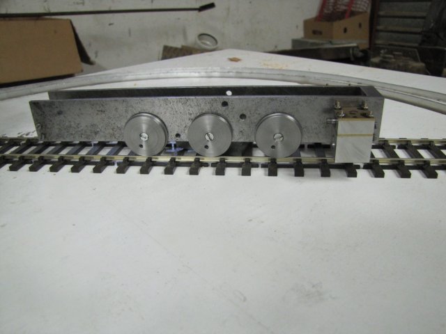
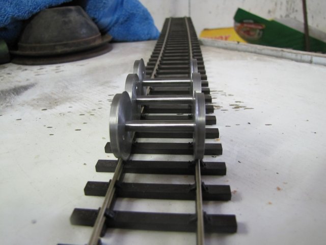
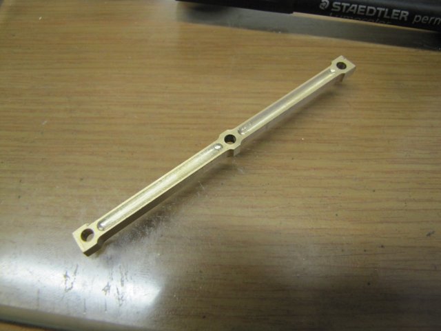
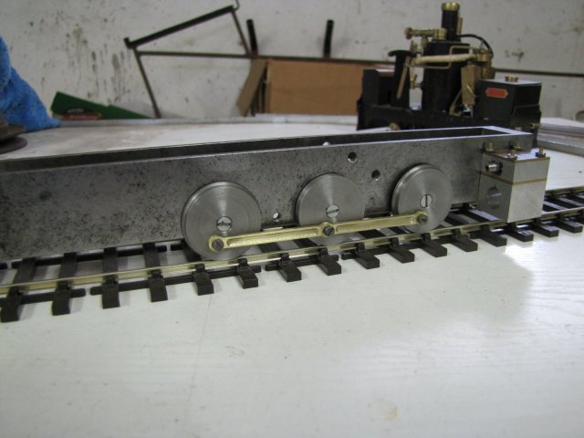
And a single-side assembly on the frames:
normal_IMG_2267.JPG


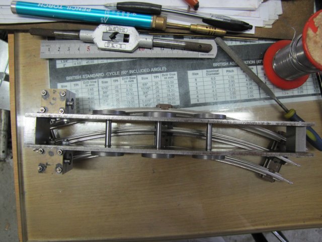
Still quite a bit of work left on the axles; they need to be machined to length, and the key ways cut in them.

After typing up this lot, I can think of alternates to the way I have done things here which would be much easier... I think I took the "long way 'round" :big: - but all good fun, even with the frustrating bits in between ;D

Regards, Arnold
 
Very interesting post Arnold.
The round keyway was a learning for me.
I'm sorry you got peeved...sorrier still there was no audio recording. :big:
 
Thanks Carl. :big: - I'm glad there was no audio recording; would have been boring... The "peep" sound in recordings seems to sound the same in all languages and just hurt one's ears ;) - and it does not help to have a parrot that can imitate it VERY well - I dare not leave the TV on on a channel that might contain peeps :-X
The round keyways are not necessarily a good option; rectangular ones work better and are more accurate; I just did it for the sake of convenience. Once I get the engine built and all issues sorted out, and if it would be a good runner, then I'll rebuild it completely from the ground up, and then tiny details like this will be properly addressed. What I'm flogging together now, and the picture of the real one in my head are two totally different-looking things; this one must just be mechanically sound sound to see if it will run.

Today's bit...

I used the stop hole in the arbour with a pin shoved in to set the depth for each axle, and then locked and fed the carriage from the feed screw hand wheel. When the first axle was to length, I took a note of the reading on the feed screw hand wheel. The other axles was then finished to this same reading to get the lengths correct:
normal_IMG_2272.JPG

Obviously, the pin was removed from the hole after the axle was tightened down with the set screws, and before switching on the lathe.

More drilling and tapping and countersinking followed on the end of each axle as well. Then it was off to the mill to mill the key slots; 1.5mm wide and 0.75mm deep. Both sides of each axle was done in one setting to keep the slots in line:
normal_IMG_2273.JPG


Then cleaned off the burrs from milling the slots (that old 1.5mm cutter seems to have had it now; I should have used a new one!) and cut 6 countersink M3 screws to length to use on the axles & wheels:
normal_IMG_2277.JPG


Well, what do you know; they actually fit the track with just the right amount of side-play ;D:
normal_IMG_2280.JPG


Assembled on the frames, and a shot from above on a 27" curve (the sharpest for O gauge - and meaning a curve taken from a circle which would have a diameter of 27") - and the reason for the blind drivers in the middle; as you can see, they are way off the track, yet the other wheels still follows the curve quite easily if pushed along:
normal_IMG_2281.JPG


Now comes the fun bits; the drive train and valve gear. I'm really looking forward to that!

Regards, Arnold
 
Earlier this week, I finished tapping the crank holes in the wheels. Just clamped all the wheels on the tooling plate with the holes to be tapped located over tooling holes and manually tapped all the 3mm holes:
normal_IMG_2282.JPG


This afternoon I started off with two strips sawn from 2mm thick brass plate:
normal_IMG_2295.JPG


These were then cleaned fairly well on one side each, and a thin strip of soft solder placed on one:
normal_IMG_2296.JPG

The other was placed on top, and I just used a plumber's torch to heat them up and solder them together.

The strips were then cleaned up and milled to 6mm width and a clean reference end. I marked for a center hole next to the reference end, and didn't bother to mark the rest; I'd do them by the dials. The workpiece was clamped to the tooling plate on top of a strip of aluminium plate (got that from an old QUICK-80 tape of which I now have a whole stack) Then I centered the mill on the reference:
normal_IMG_2297.JPG


And then drilled three 3.2mm holes in it at the same spacing as the axles. I only needed 3mm holes, but made the holes slightly larger to allow for slight variations in wheel positioning, as well as to allow a bit of pivot in the holes once mounted, as the wheels can move from side-to-side by about 0.8mm:
normal_IMG_2298.JPG


That would have been all that was needed for the experimental engine, but I got a bee in my bonnet and decided to try and be a bit flashy for a change, so I tried out my new 4mm ball nose mill - just 0.6mm deep into the brass:
normal_IMG_2301.JPG


Just couldn't leave things at that, so I took away a bit on the sides as well:
normal_IMG_2302.JPG


And ended up with this lot:
normal_IMG_2303.JPG


Just had to try and keep my filing skills in shape, so filed the pointy bits approximately round, and then re-heated with the blow torch to separate the two pieces. Then spent a couple of minutes to remove the solder from the back sides with some emery paper. Net result:
normal_IMG_2304.JPG

Can anybody spot the booboo I made ?

At least the booboo is visual and not mechanical; the rods fits nicely on the wheels, and there is no sticky bits when rolling along the rail. I still need to make up some proper mounting screws and spacers though:
normal_IMG_2305.JPG


Regards, Arnold
 
Excellent build thread Arnold!!
Really enjoying reading and following your progress here!

Does your Myford have the taper turning attachment?
I see something attached to the back side that is not on mine.

Andrew
 
Hello Arnold, always a pleasure it is to follow your work, this one is no exception to that rule. Do you have plans for a tender for your loco? One of the reasons I ask is it would seem the moment of the frame rails will be quite acute and wonder how that will effect any coupling issues down the line (oh, no pun intended, sorry :hDe:)

regards

BC1
Jim
 
Arnold,
Liked the soft solder trick - make mental note.

At the begining of this thread you said you are not really working to plans. Seriously - are you doing all this out of your head or sketching as you go along ??

Ken
 
Thank you Andrew :). Yes, it's a taper turning attachment. It doesn't get used too often though; normally it's just a swarf trap and a handy-dandy place to mount my magnetic base for the dial indicator or DTI when clocking things up in the 4-jaw chuck. On the rare occasion where it's needed though, its a good bit of kit to have, and I'm fortunate my lathe came with it. From what I've seen, they cost silly prices to buy, and if I didn't have it, I'd rather spend the silly price on a quick-change gearbox ;)

Jim my friend, thank you! Hmm... The loco is supposed to get a tender as I want water and fuel in it, and you raised a very valid point! - On tight turns coupling will be an issue, so I have to think a bit. The frames are overly long toward the back, so I can shorten them, but then I might have balancing issues; not too difficult to sort out though. Just like real life - I never seem to get a good angle on the coupling thing; prospects for St. Valentine's day tomorrow are a bit slim :big:

Thanks Ken. I have simulations of the valve train, but no real drawings - except for the measurements needed for it. So I'm mostly going by what I have in my head, with some rough sketches where I need them. Once things look good to go, I'll take the final dimensions and draw it up in CAD properly, so that I can build a good one.

Not much done on the loco today...

Some 5mm hex brass, turned down to 3mm and threaded M3 for a bit:
normal_IMG_2312.JPG


After parting off and repeating, I had the outboard rod bolts - with a dud that I parted off slightly too short (the head is too thin) as I was doing things by eyeball rather than properly measuring:
normal_IMG_2313.JPG


Having made those, I was hit by "designer's block" - and I wasn't in particular interested in small work today, so I made up some clamps for my tooling plate - I'll post that in my tooling thread.

Regards, Arnold
 
Just like real life - I never seem to get a good angle on the coupling thing; prospects for St. Valentine's day tomorrow are a bit slim.

Chuckle, chuckle.
 

Latest posts

Back
Top