Potty Simpson and Shipton Short Stroke Engine

Home Model Engine Machinist Forum

Help Support Home Model Engine Machinist Forum:

This site may earn a commission from merchant affiliate links, including eBay, Amazon, and others.
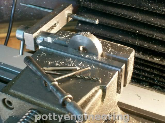
For those of you who don't know what a sine bar look like hers mine:

131_1601.jpg


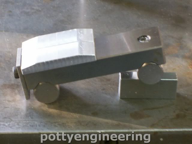
The bar is made to a very accurate length between the rollers and you just pack one end up to give the desired angle, that you calculate using the sine function.

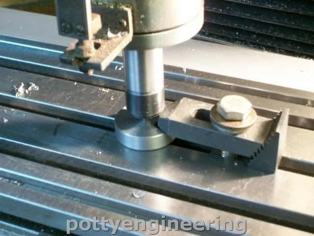
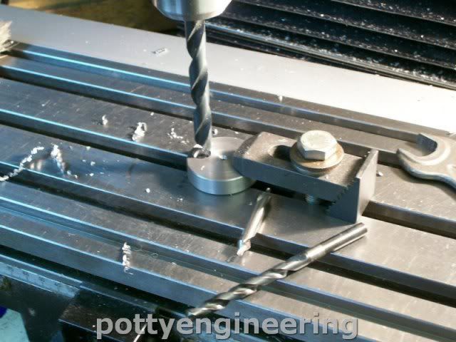
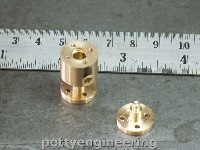
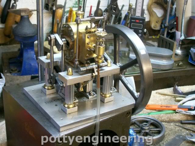
Finished off the base by drilling the holes, the outer holes were countersunk flat bottom to take the bolting pads and the centre hole for countersunk for the cap screws.

IMG_0666.jpg


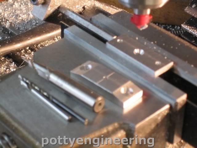
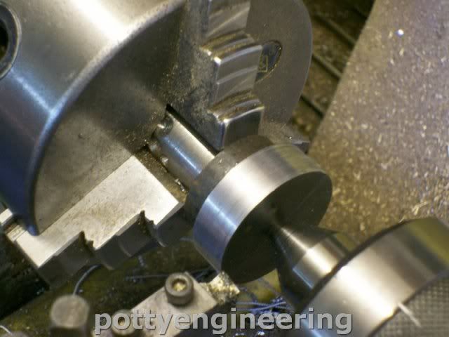
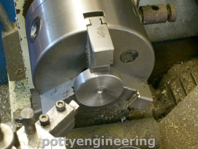
Then turned up the pads.

And the bearings.

131_1602.jpg


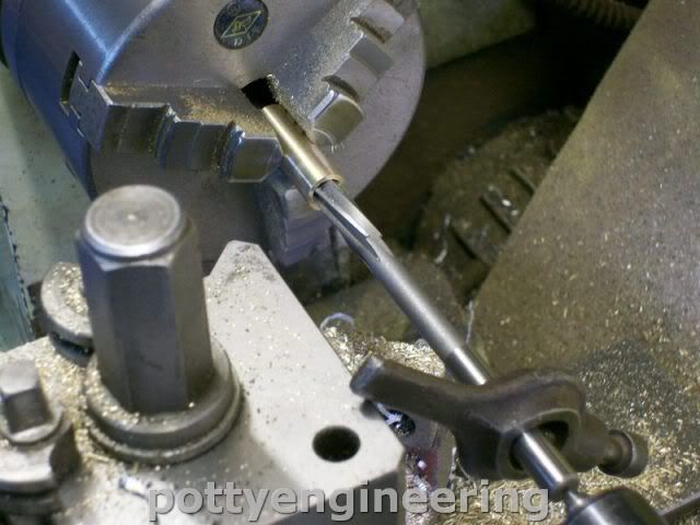
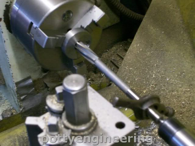
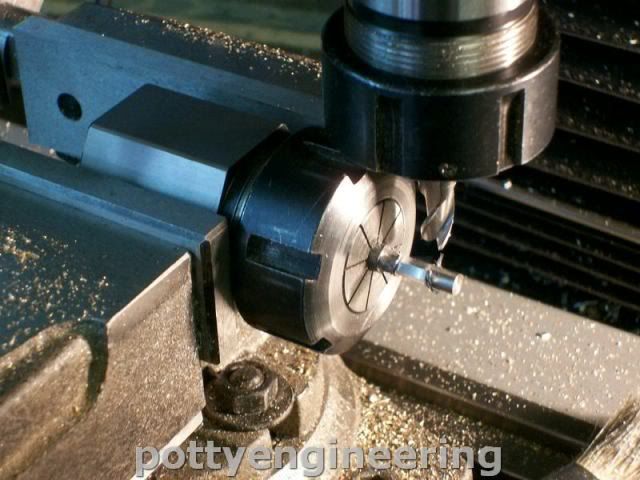
I like to push the reamer through with a centre with a drive carrier, that way it floats and you cut a true size.

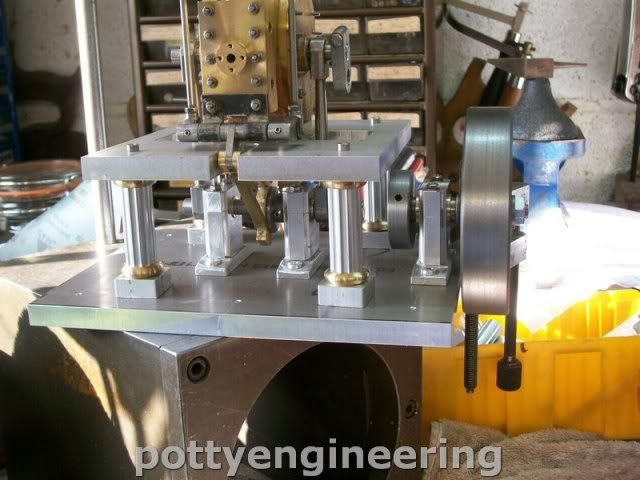
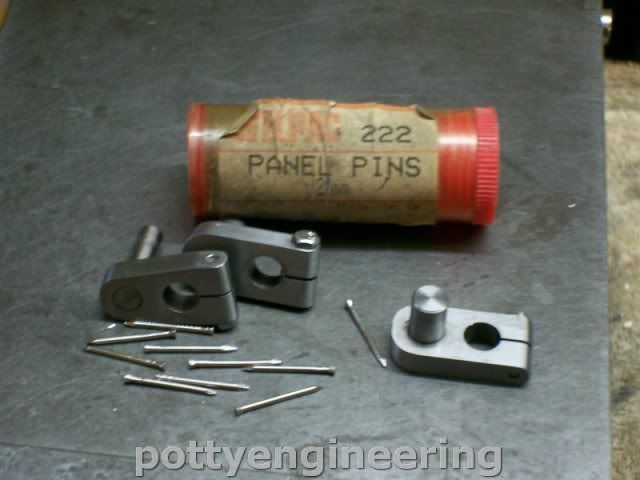
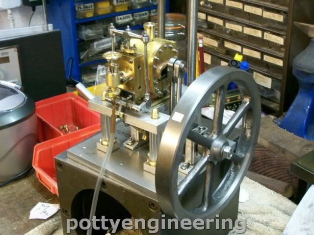
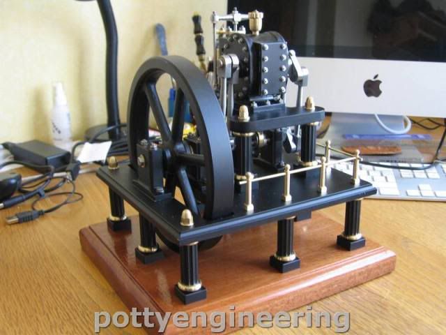
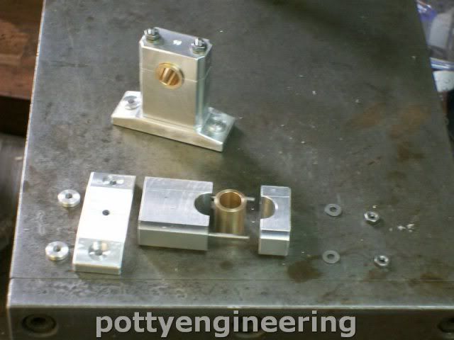
This is how it all assembles together.

131_1605.jpg


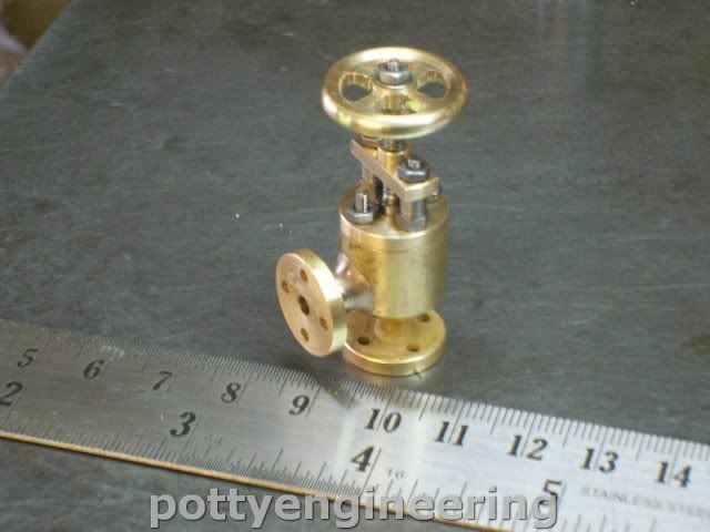
Then stuck the lot together with JB weld gave it 24 hrs to cure then cleaned them up.

131_1612.jpg


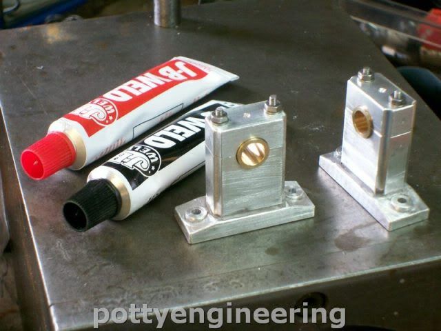
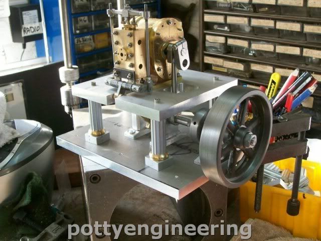
Now they look good:- a big thanks to Jason and Ramon for sharing the method its one I will use again in future.

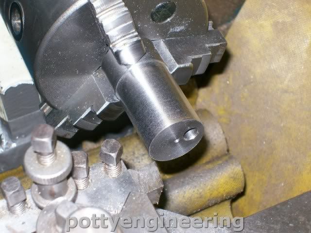
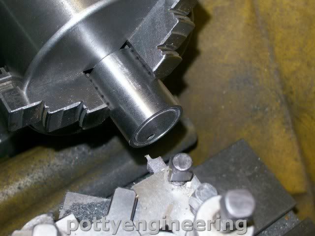
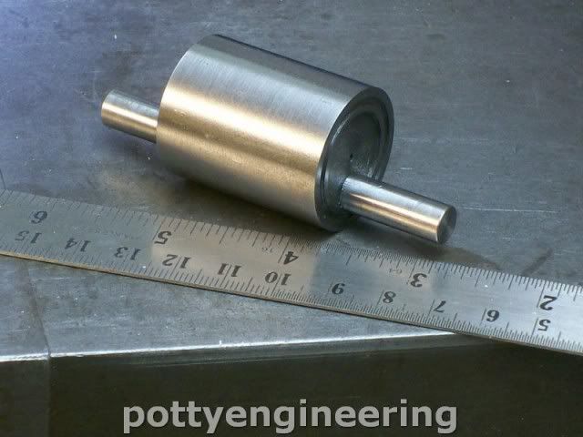
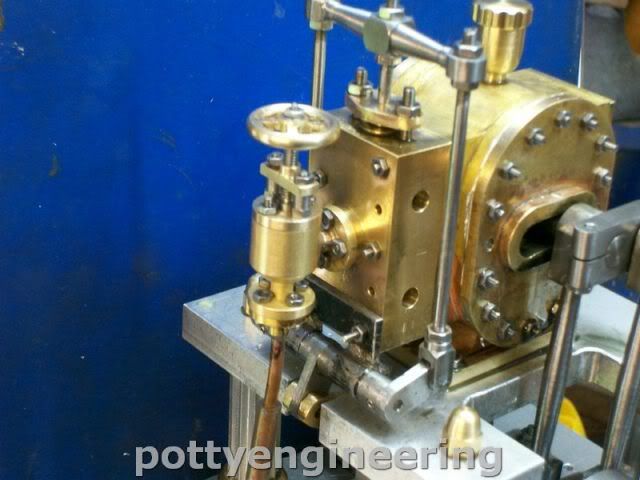
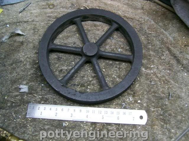
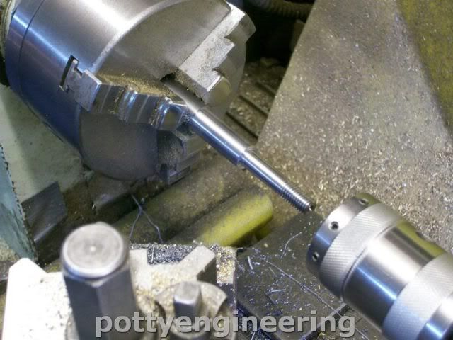
One more bit made the drive half shaft. I was going to make it from 12mm bar, but didn't have any so used 15mm and turned it down to 12mm with an 8mm step for the fly wheel threaded M8

131_1606.jpg


Stew
 
Managed to sneak a couple of hours in the shop this morning thanks to my grandson, the little darling had been playing with my bed side clock and put it forward 1 1/2 Hrs so bright and early I was up at my usual time, it was only when I looked at my shop clock that I noticed how early it was

::) ::) ::) ::) ::) ::)

Made the fly wheel drive for this I needed at 36mm dia * 10mm slice of mild steel I hadn't got any bar but I did have some 1/2" thick *
1 1/2" steel bar, so I cut of a 1 1/2" length put a centre drilled the middle and then used a friction drive to turn it into a disc.

131_1626.jpg


Then skimed the faces up.

131_1628.jpg


Set it up central on the mill and put a 12mm off set and drilled 9mm

131_1632.jpg


131_1631.jpg


Then drilled and reamed 12mm through the middle

131_1634.jpg


Drilled and tapped M3 for a fixing grub screw.

131_1635.jpg


Then made a 6mm bush for the crank drive and pressed and pressed it into the disc.

Time for a few hows it looking shots.

131_1638.jpg


131_1637.jpg


Stew
 
It's coming along nicely Stew, and those supporting columns are outstanding.

Jim
 
Thanks Jim

Things have been real slow on this engine due to family commitments but have managed to steal an hour or two her and their.
I had to do a major sculpturing job on the base, it was my own fault instead of following the drawing I changes the hole centres for the pedestal as i thought they would make thing look more symmetrical, but I forgot about the impact on the length of the crank.

Any way with that sorted I've spent some time getting my head around setting the timing:- not easy as you can't get at anything.

But I have had it running for short time, but it will only run with lots of oil in the cylinder, I think I have to reduce the clearance of the piston, which will be a major strip down, but the positive thing is that It will run, as soon as I get a longer run out of it I'll post a video.

Stew
 
[ame]http://youtu.be/0KZoRF8AhRU[/ame]

I think I may have run up against the limitation of the design it will only run for a few seconds with my small compressor before it runs out of wind.

After all they only ever made two of them i guess thats why.

Stew
 
Great stuff. It runs well and looks great. Who can ask for anything more. Congratulations.

Jim
 
Cheers Jim/Brian

Still a bit along the learning curve to go with this engine.

To days lesson:-

I made the piston from PTFE it seemed a good idea at the time, I know PTFE has some strange properties and that it has a high figure of coefficient of linear expansion, but I though that shouldn't pose any problem, I measures the width of the piston and the cylinder up and made them so that I had about 0.2mm clearance fit, I reduced this down to 0.05 to try and get a better run, but as I was doing this I was having problems getting a repeat size for the piston, this morning I stripped the engine down and measured things up the clearance was size for size, great i thought, tried it for fit and it all rolled over smoothly I fiddled about a bit, tried it for fit and things had tightend up, measured up again and I had an interferance fit ???

Time for my morning coffee, so stuck the piston in the fridge for 1/2 hr measured up again and it had shrunk by 0.15mm.

Just done a google search on the properties of PTFE and as far as I can tell it has coefficient some 5 times greater than brass.

Time for a change of material i have some nice shash weight cast iron that John gave me I'll give that a try.

Stew
 
Hey Stew,

I use teflon piston rings with a stepped lap joint to allow for differential expansion. in my launch engine

Like this


teflonpistonring.jpg


I know your engine doesn't use rings in the traditional sense, but was wondering if there was a way to allow for the thermal expansion mismatch......

Dave
 
Thought I'd better update the build log

1st making the cast iron cylinder.

Turning to size after drilling off set hole

131_1658.jpg


The trepanning a groove for some packing,

131_1663.jpg


seems to work ok without packing tough, still nice to have the option.

Shaft assembly using same method as for the PTFE

131_1675.jpg


Also pinned the crank journal using soft nails.

131_1648.jpg


Then whilst waiting for deliver of new 7" fly wheel made the stop valve, body fabricated in two parts silver soldered together.

131_1679.jpg


Get to use the new ER32 indexing blocks to cut an hex for the valve pillars.

131_1681.jpg


Worked a treat :thumbup:

Completed valve

131_1686.jpg


And on the engine

131_1689.jpg


Stew
 
Thanks Jim

I'm sorry to miss you at Harrogate this year I usualy go, but family commitments make it dificult this year, unless their is a change I won't be able to make it.

On Friday I took delivery of a 7" flywheel casting from RDG.

131_1693.jpg


Good quality a few blow holes on the rim but nothing that couldn't be skimmed out or filled.

This morning I finished off machining it and tried it out on the engine.

131_1708.jpg


131_1705.jpg


It's more in proportion to the fly wheel in the etching of the original.

rotss2a.gif


Its improved the engine running considerably, it now runs at about 10 - 15 psi at about 100 RPM at full pressure of 60 psi it runs at 550 down from 850 for the 4" wheel. Still got an horrendous wobbly on the wheel but that's down to the single bearing support, I'm hoping to get some plate delivered next week that will allow me to double up the bearing supports on the fly wheel that should smooth things out even more.

I'm now about 99% happy with this engine

:D :D :D :D :D :D

Stew


What a pity you are not going to Harrogate. But how about turning on Skype and we can have a chat when our time zones coincide.

Jim
 
Stew,

Those RDG flywheels really are a very good buy, especially when you look at the crap that comes from the big casting retailers, theirs are usually almost unusable, with massive inclusions and misaligned spokes. It is easier to make your own than to try to use one of theirs.

I keep a few in stock, just in case I get the urge to make an engine.


BTW, nice gumbeating session on Skype last night Jim, as I said, it's good to put a face and a voice to a name.


John
 

Bit of an update

Got the new base for the larger fly wheel made and the bearing housing plus one or two other bits, cleaned it all up and got it prepaired for painting but bin held up on this front due to the rain we've had the last couple of days. Taking the base round to men in sheds to have it planed and edged.

With a fair wind i should have it compleat next week.

Stew
 
Well got it all together

IMG_3686.jpg


IMG_3689.jpg


I'll show some smatter pics and a vid later, at the moment i've got my Boss breathing down my neck, I've bin a bit obsessed with this engine, and the jobs are building up.

I think it looks great but my boss said its a bit too Tarty for me

:big: :big: :big: :big: :big: :big:

Stew
 
That looks awesome to me Stew!

Great Job...looking forward to the pictures!

dave

 
Thats turned out nicely Stew, I do like the understated black and you have just anbout the right amount of exposed metal so it does not look too blinged up.

Look forward to the video.

J
 
ooooww.

That's very nice Stew. :bow: :bow: :bow:

Vince
 
Back
Top