Three Cylinder Radial Steam Engine

Home Model Engine Machinist Forum

Help Support Home Model Engine Machinist Forum:

This site may earn a commission from merchant affiliate links, including eBay, Amazon, and others.
Thanks for fead back shred, no ones shouted at me so I think i'll just goahead and post the drawing when I'm done.

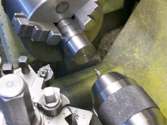
Any way not so cold today so got the pistons finished.

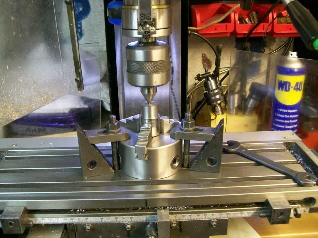
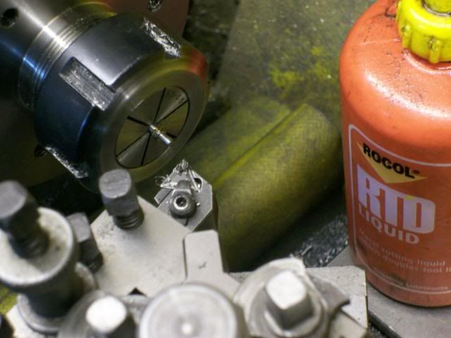
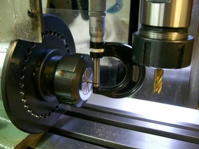
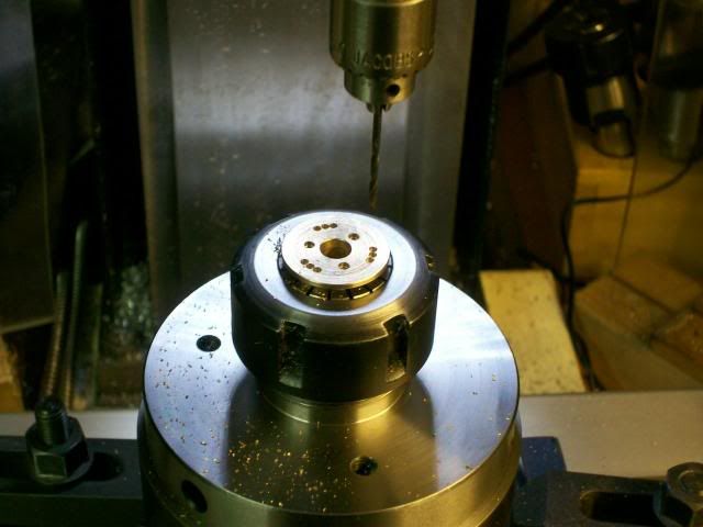
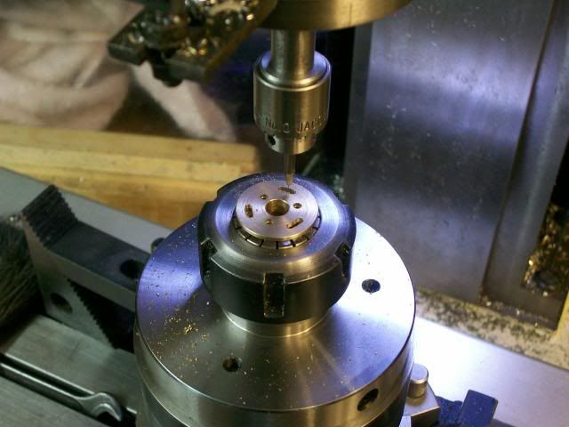
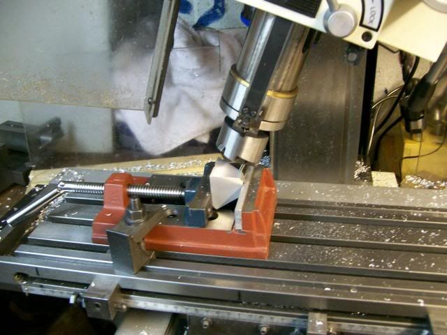
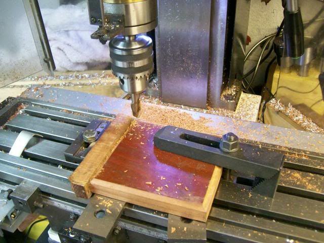
Set up for drilling gudgiun hole. find edges and index to corect position, all three were drilled from the same setting

100_3196.jpg


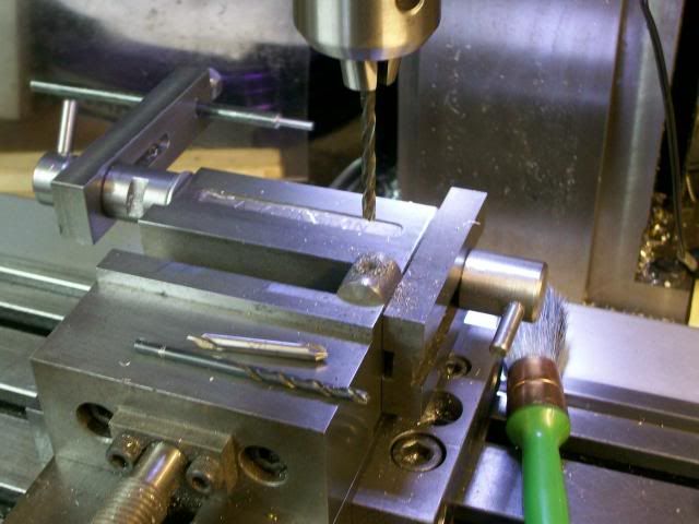
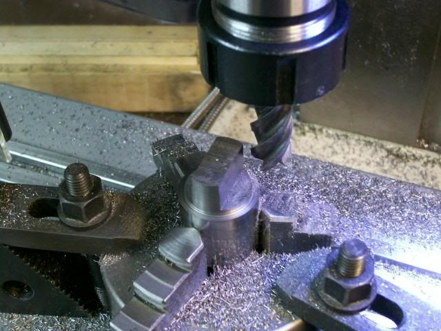
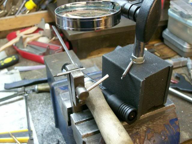
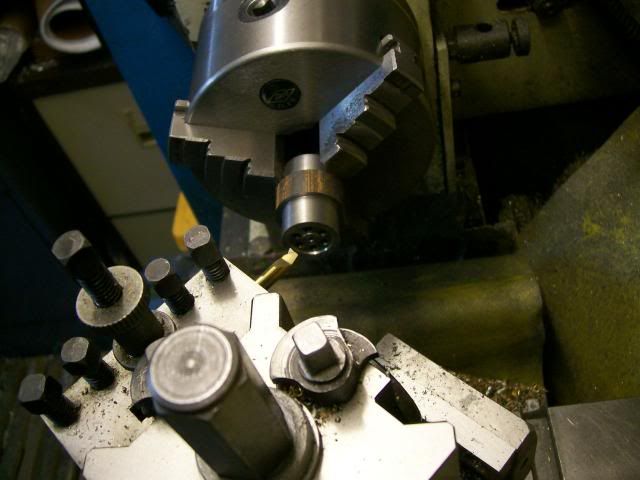
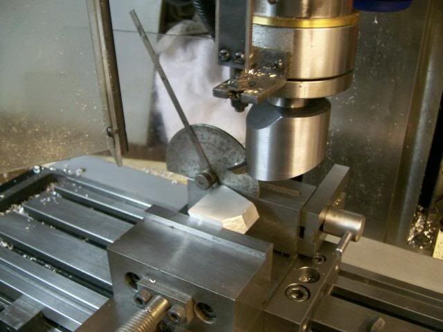
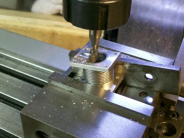
The inside of the piston requires milling out to give clearance for the con rod little end.

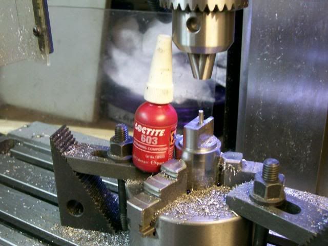
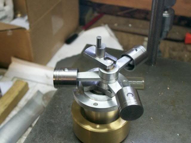
This is the set up, a length of 4mm rod was inserted in gudgion pin hole then squares this up to the vice,

100_3197.jpg


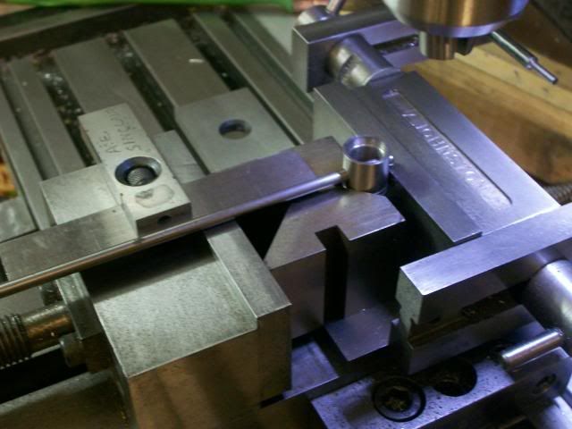
At my first attemp I used a 3mm slot drill but broke it so went up the a 4.5 end mill that worked ok

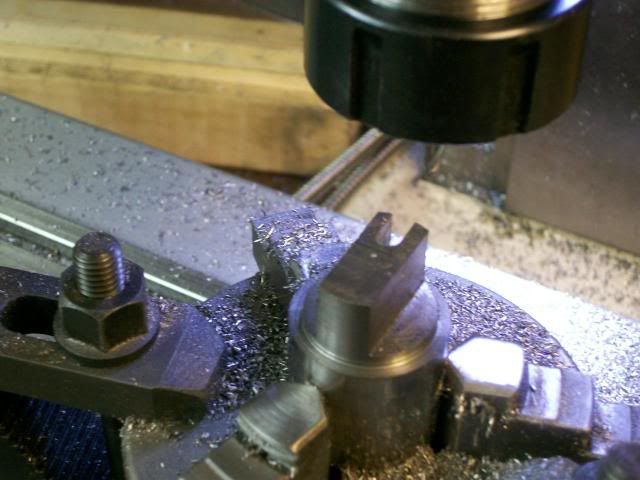
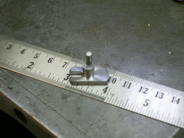
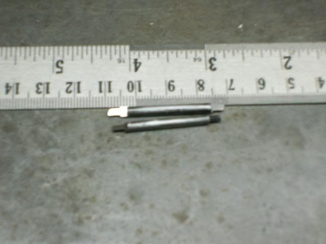
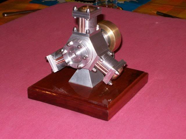
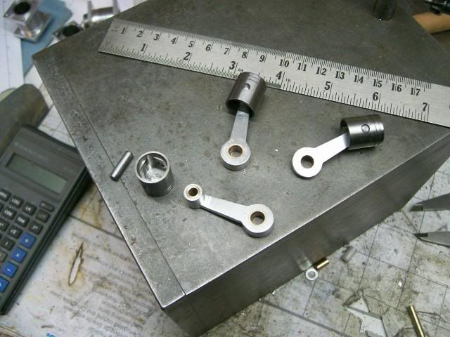
And her they are done
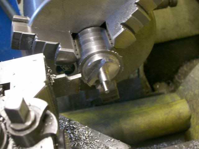
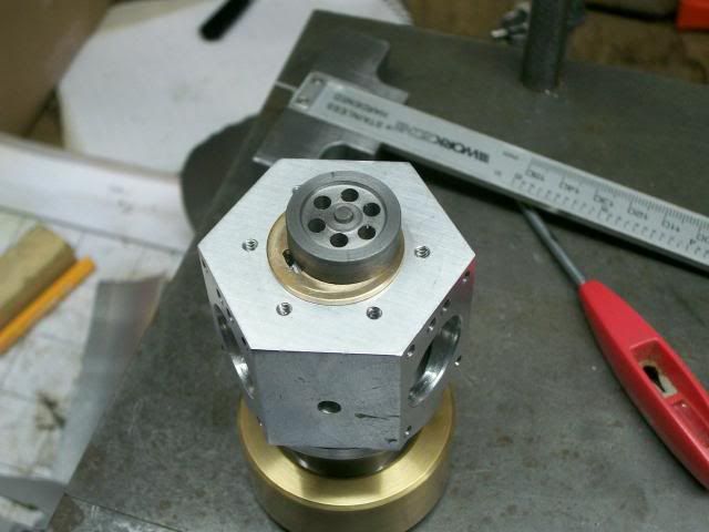
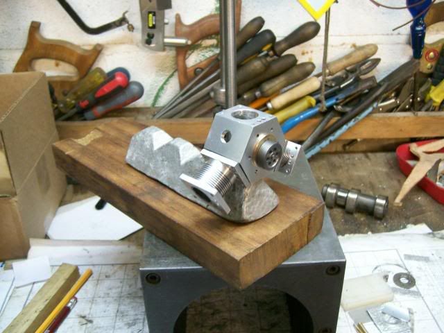
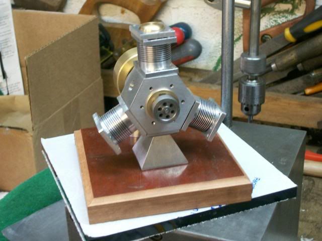
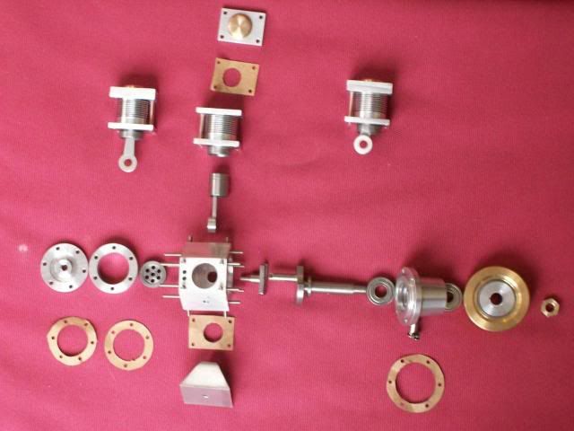
100_3200.jpg


And on the crank

100_3198.jpg


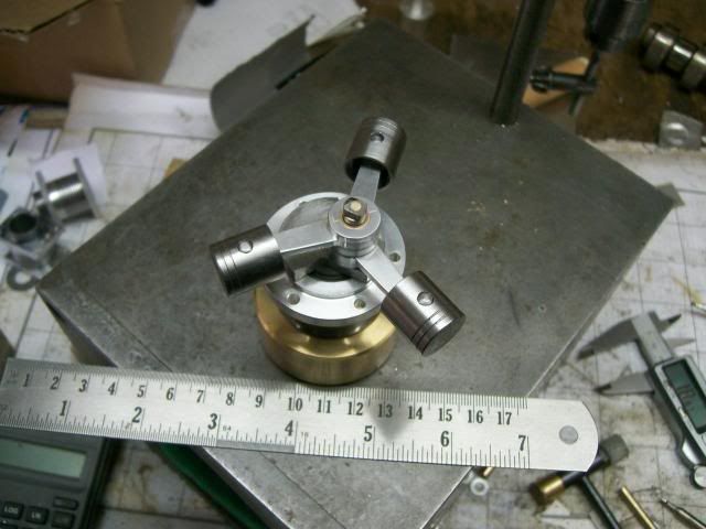
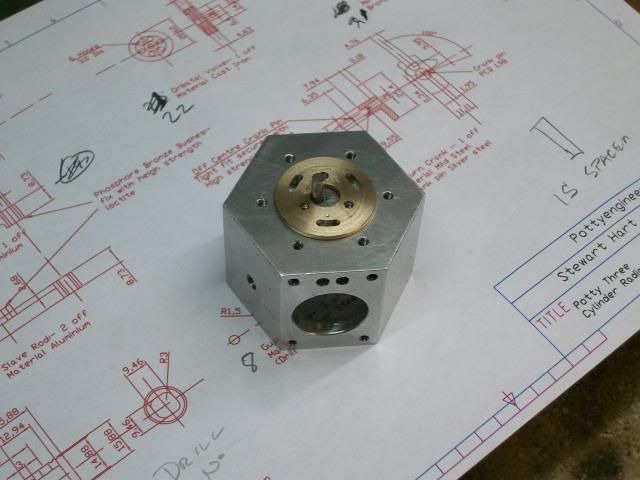
I've just got three bits to make before I start assy and test, so I've attached the drawing that shows these last three bits

Have fun

Stew

View attachment Sht 4-Model.pdf
 
Thanks Chaps

A good afternoons work today making the return crank, this is a tricky little beast, I've had a good head scratch over it, all the drawings show it as one piece, however I think it will be easyer to make as two pieces and still function correctly.

The drive pin is positioned relative to the drive slots and its position times the engine, you can get the position with a rotary table or you can use cordinates from the centre line, I've dimensioned the drawing so you can use either method.

OK first job chunk of 30mm free cutting mild steel in the lathe turn down to 1" and put a small centre in the end,

100_3202.jpg


Keeping the job in the chuck transfer the chuck over to the mill with a centre in the quill wind it down tight into the centre in the end of the job, clamp the chuck to the table, Zero your dials or DRO, You've now got your centre datum.

100_3204.jpg


Then mill the face up to get rid of the centre its done its job and it will only get in the way down line, mill flats and then mill drive slot 3/16"

100_3206.jpg


100_3207.jpg


Then to accuratly locate the drive pin move to drawing cordinates.

100_3211.jpg


Centre drill then drill with a number drill to give a tight fit on 1/8" silver steel, spot of loctite and press pin in using mill head.

100_3213.jpg


Transfer over to lathe turn diameter and part off,

100_3216.jpg


Face up the back, and thats the beast tamed.

100_3222.jpg


and this is where it fits on the crank

100_3228.jpg


Have fun

Stew


Thanks Stew.
I like the way you go about your work there. I guess, 'cause it's how I try to do things, although I think you have a better handle on how many operations you can get out of a single setup.
It's kind of a fun part of the game, for me.

Your work looks just great!

Dean
 
Looking very nice Stew. Excellent workmanship.

Regards the copyright question you asked about. From what I can see you have an original design, or at worst case a derivative work based on two designs. So from my view there is no infringement of any kind. Thanks for being concerned about it. One good copyright suit could severely strain HMEM activities so we strictly enforce copyright law here.

Thanks for sharing this build and your drawings with HMEM.

Gail in NM
 
Dean/Gail

Thanks for your kind comments,

Dean:- working out the set ups is certainly the good part of the hobby, I find myself thinking ahead all the time about the next parts I'm going to make, you can do this at any time, but not when the wife is talking to you, that can be painful :big: :big:.

Gail:- Thanks for feed back on the copyright question, I'd hate to cause this great forum pain.

Cheers

Stew
 
what an interesting thread we have here sbwhart!!!
I liked very much everything but particularly the part about cylinders and pistons :bow:
very nice finish and tight tolerance

I'm sorry only that your mother in-laws didn't want to try the ultrasonic cleaner on her teeth :big:

 
ariz said:
I'm sorry only that your mother in-laws didn't want to try the ultrasonic cleaner on her teeth :big:


Ariz thanks for your nice comments.

As for ultrasonic cleaning mother in-laws teeth, perhaps next time I'll let her take them out :big: :big: :big: :big: :big:

Have fun

Stew
 
Shop time over the last couple of days has been a bit restricted by other commitments. Any way managed to get a few hours in and complete the port flange. By way of a off topic but related bit of kit I took delivery of an coax indicator, I got it from amadeal on ebay www.amadeal.co.uk at £44 + post it was the best price I could find in the UK.

100_3250.jpg


Its quite a long bit of kit and I was strugling with head room what with my rotary table and collet chuck adding to the height, then I remembered a tip from a friend that I could use M3 collets this would give me an additional 3" of room to play with. The coax has a 10mm shank but my collet set is imperial so i made a split collar to use with a 1/2" collet (note to self get a metric set of M3 collets).

So her we are

100_3253.jpg


And this is how you use it.

100_3251.jpg


With a stylus in the bore (or OD) and the outrigger stopped with a magnetic stand, this is to stop it whizzing round and to keep the dial facing you. Run the mill at about 200 rpm, adjust one direction to a point where you get the least dial movement, do the same in the other direction, repeat again, repeat again, after three interation you should end up with zero movement, and thats it you're on centre line, a lot easyer and quicker than having to crane your neck with a dti.

Back to the port flange, for my first attemp I used a bit of scrap yard alluminium phospher bronze, but this material was up to its usual tricks and was a ***** to machine, I don't know now why I tried it. Made onother from a nice bit of free cutting brass, this is a straight forward turning job so no pics.

Now for another bit of off topic but related. The ports are 2mm wide and I don't have a 2mm diameter cutter, cutters this size cost an arm and a leg, and I can't see me using this size very much, but I remember reading that in the "good old days" people would use a D bits to cut the steam ports for model loco, so I set too and made some 2mm dia D bits.

Truning the dia

100_3235.jpg


Sectioning to 1.1 mm:- 0.1 above centre

100_3243.jpg


I blacked the cutter up so I could see what I was doing then with a fine file and under a magnifying glass I backed the cutter off.

100_3245.jpg


Heated them up to cherry red and quenched in water, then gave them a rub on a stone to sharpen the edges up, and her we are done.

100_3249.jpg


To machine out the ports I decided to use the PCD function on the DRO combined with the movement of the rotary table.

Centre the job up using the Coax indicator.

Set Rotary table on zero deg

Set PCD function to drill 8 BA clearance for the clamp screws and drill.

Then set PCD function for port position, drill 1.8 mm hole in each port position using DRO.

Rotate RT +13.5 deg use DRO to drill 1.8 mm at each port position

Return RT to zero then back -13.5 deg use DRO the drill 1.8mm at each port position.

Her we are with all the holes drilled

100_3255.jpg


Then using the little D bit join the holes up by rotating RT 27 deg.

100_3258.jpg


Thats it job done, her it is in position. The D bits worked great them milled a nice accurate 2mm wide slot.

100_3261.jpg


I've completed the assembly drawing for the engine so I've attached it to this thread.

Have fun

Stew

Amend

Whoops forgot to add drawing :- done it now


View attachment Sht 1-Model.pdf
 

Got the Orbital Valve machined up, you have to get the thickness of the valve a very accurate fit in the valve chest, so first thing I did was to measure everything up, to determine what thickness it needed to be. Turned up a chunk of cast iron, transfered it over to the mill still in the chuck, well by now you should know the routine, drilled 6 * 1/8" holes, then back onto the lathe to finish off, the under cut face

100_3263.jpg


Parted it off then pushed it hard up against a parallel in the chuck (don't forget to remove the parallel) then faced it off to thickness + 0.20 for lapping each side, and undercut the face.

And her it is in place, you can see the open valve port on the left the other ports are closed off.

100_3267.jpg


At this point I thought thats it all the maching done, but no I've forgotten the stand.

Have fun

Stew
 
I'm enjoying following your build thread. I notice you have a lot of ER tooling, including an ER collet spin fixture. Did you fabricate that yourself?

Chuck
 
Hi Chuck

I've tried to adopt the ER collet system to my kit, my lathe is an elcheapo 3 in 1 that I've removed the mill drill so I guess its a 3 - 2 now, sorry for the pun, and a seig X3 mill.

My ER kit consist of a Stevenson spin indexer that came with a 5C to ER 32 adaptor, this is it http://www.arceurotrade.co.uk/Catalogue/Collets/5C-Fixtures, I've got a ER 32 lathe collet chuck that I adapted to fit my lathe, for my rotary table I made a back plate that will fit lathe chucks and the ER 32 collet chuck, I made it from store supplied parts this link will show you what I did http://madmodder.net/index.php?topic=1330.0. I friend also made me a similar adaptor for the Indexer that will take chucks information her http://madmodder.net/index.php?topic=2304.0

What I was trying to do is get interchangeable tooling that I can move from the lathe to the indexer or rotary table and back again, and keep the work in place this saves time in setting up, clocking true etc, and improves accuracy.

Hope this helps

Stew
 
The valve looks good, Stew. Is it from hot rolled rod?

SBWHART said:
What I was trying to do is get interchangeable tooling that I can move from the lathe to the indexer or rotary table and back again, and keep the work in place this saves time in setting up, clocking true etc, and improves accuracy
Stew

Have been working on this for a while, myself. So much time in my shop is spent setting up, and re-setting up on different machines. I'm getting there, but it's a process doing tooling projects between the other fun stuff. It's nice to see the other fellow's methods.

Thanks for the update on your engine.

Dean
 
Thx, Stew. Looks like a handy setup.

Chuck


Thanks for your nice comments and support Guys.

Got some work done on the stand, had a sort through my stash and came up with these bits.

100_3269.jpg


I had a square of black plastic that I was planning to use for the base but it was a bit on the thin side and the proportions didn't look like, that chunk of wood looks a bit thick as well. scratch.gif

Any way made a start on the upright I'm using a bit of ally ingot, its nearly a pyramid, cleaning up the sides.

100_3273.jpg


It was getting a bit difficult to clamp so tilted the head of the mill.

100_3275.jpg


Found a thinner bit of hard wood under the bench that's is a bit thinner. don,t know what sort of wood it is, its a nice gingery red.

Squared up the edges in the mill and used a radius cutter to sculpt the edges.

100_3277.jpg


And thats what its going to look like, I need to get some sand paper to clean it up a bit more but it looks OK.

100_3278.jpg


Made a start on tidying things up and assembly, I,m not a great one for making things too shiny, its just a personal thing, I like them to display honesty and bare witness as to how they were made.


Have fun

Stew

 
That is REALLY looking good Stew - great job!

Regards, Arnold
 
Thanks Arnold

Bit of a short update:- started assembly work, but soon realised that I'd forgotten to mill the 10 deg air pasage in the cylinder, decided the best way would be to use my 2 1/2" sine bar, her it is set up with the corect packing.

100_3280.jpg


And this is how it was used to

100_3281.jpg


Want to try gaskets made from brown paper stuck down with grease, these are the gaskets ready for use, with the tools of the trade.

100_3283.jpg


Spent a fair bit of time makeing and fitting studs and putting the air pipes in the cylinders and giving thinga bit of a tidy up, tried assembling things losely together it all seems to fit.

And this is all the parts exploded.

100_3291.jpg


If I can get the chance I'll start final assembly this afternoon and a trial run, fingers crossed.

Have fun

Stew

 
Looks like you're getting close, Stew. You're sure doing a nice job with this.

Chuck
 
Good luck with your engine, sure bet that it'll run as good as it looks.
 
Very nice, Stew.

The end is near ;D

I think you'll like using the gaskets.
 
Thanks for the good wishes guys.

Didn't get the assy finished today just got a few studs to make, and a hole to drill in the base, started to get tired, thirsty, and cold, so called it a day.

I don't know what you lads think but you don't really start to under stand an engine until you assy it and try to get it to run.

I decided to fit the bearing housing to the crank case with studs and dome nuts, it would have been easyer to use cap screws, the studs meant I had to line them up and at the same time get the crank lined up with the big ends in the con rod and the return crank, I havn't fiddled around so much since the first night of my honeymoon.

Rof} Rof} Rof} Rof} Rof}

Any way couldn't resist trying out on the base to see what it looked like, so here's a taster:-

100_3297.jpg


Don't half look OK don't it ?

Thm: ;D ;D ;D ;D

Stew
 

Latest posts

Back
Top