Potty Lads and Dads Mill Engine

Home Model Engine Machinist Forum

Help Support Home Model Engine Machinist Forum:

This site may earn a commission from merchant affiliate links, including eBay, Amazon, and others.

SBWHART

Project of the Month Winner!!!
Project of the Month Winner
Joined
Jan 17, 2009
Messages
887
Reaction score
81
I have an old works friend who's just getting started in Model Engineering along with his 11 year old son who's his showing a great interest in engines with a developing tallent for 3D CAD. Chatting to them got me thinking about an engine that could be built in a relative short time with limited equipment and I came up with the simple mill engine design that I showed the drawings her http://madmodder.net/index.php/topic,8128.0.html (be warned it has mistakes) that a Dad or Grandad could make together
Hence Lads and Dads.
The design is based on this engine that I saw at the Northern Mill Engine Association at Bolton at their Christmas steam up.
http://www.nmes.org/
IMG_3918_zps6799dda3.jpg

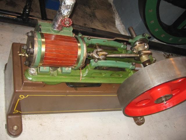
I've used standard bar stock size to eliminate milling along with a piston valve, the fly wheel can be a standard 4" Stuart wheel or a fabricated one, I will also use lower cost material avoiding as must has posible copper based alloys.
Any way thats enough of that lets get on with the job,
You will need a small lathe an 1/2 decent drill with a good drill vice and some way of accuratly marking out like this

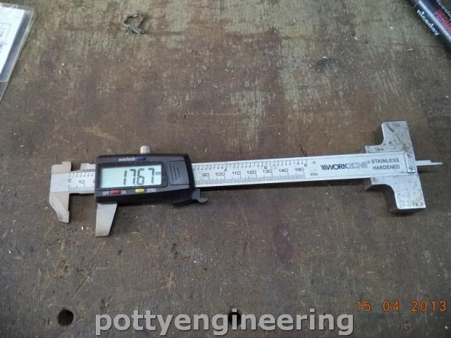
Just a cheep dig caliper with the legs cut back to form a set of odd legs
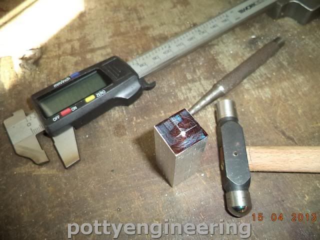
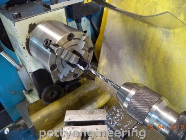
First Up the steam chest from 5/8 square ally. Cut a chunk off the bar face off to length in a four jaw and mark out the position for the piston valve.

The back into the four jaw and using a wobble bar set the centre pop running true

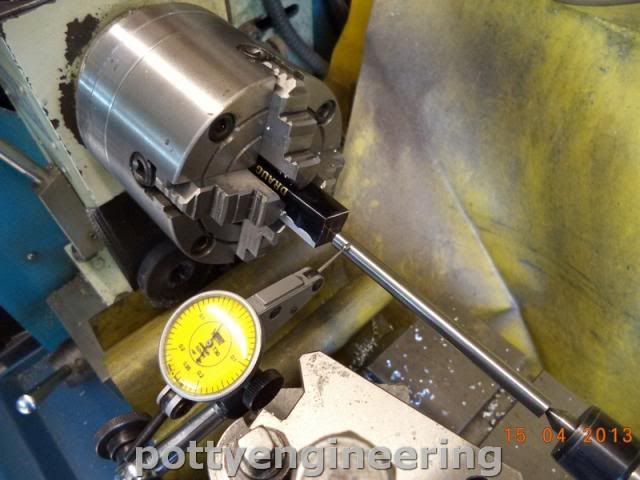
Deep centre drill then to avoid the use of expensive reamers drill through with a 5.9mm or a 7/32 drill this will cut over size and make the hole near to dam it 6mm, if the bar you're going to make the piston velve out of is a bit tight just lap it down for a nice slide fit.

Then accuratly mark out the position for the inlet ports don't centre pop them, into the drill vice and line up with a sticky pin this is just a pin held onto the chuck with platercene and nudged until it runs true. Clamp the vice to the drill table

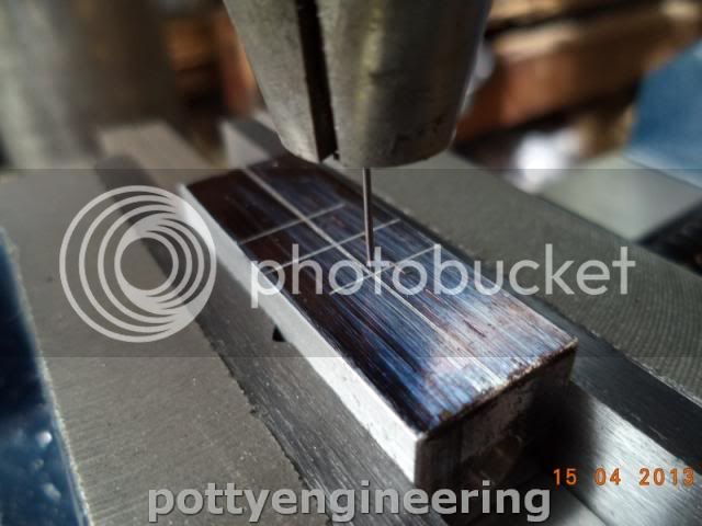
The start with a small centre drill then follow up with a 3mm drill, don't unclamp the vice from the table just losen the jaws and slide the job along to line up the second hole again with the sticky pin a drill that one, do the same with the exhaust holes.

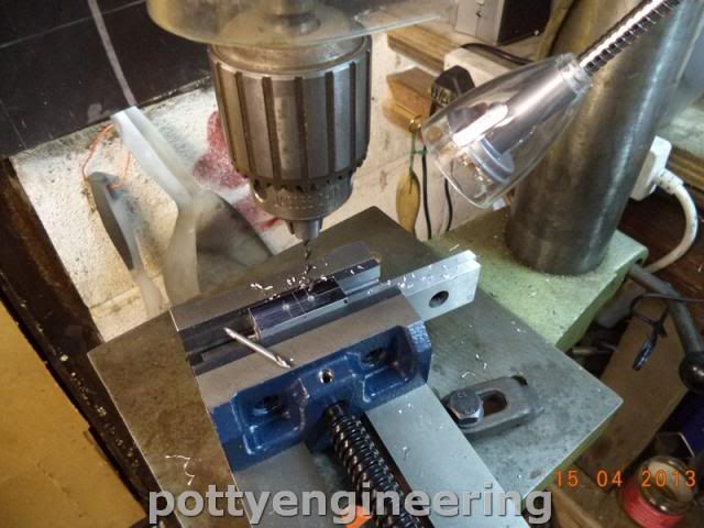
Mark out for the position of central inlet fead, and the 2mm dia clamp down holes, you don't need the sticky pins to line these holes up as their positions are not as critical just use the centre drill.

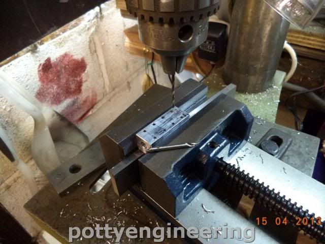
Thats it job done, just a few more holes to drill in it off the inlet and rod gland fixtures when they are made.

The deburing tool is what my late Dad made I can tell he made it as it's got his personality writen all over it.
Stew
 
Thanks for your post but I need some help in understanding the reason and use of the cut back caliper blade. Did you add the piece at the bottom for more accurate depth measuring, if you did please show a couple of more photos so I can see the construction.
Thanks
Mr.Chips
 
Thanks for your post but I need some help in understanding the reason and use of the cut back caliper blade. Did you add the piece at the bottom for more accurate depth measuring, if you did please show a couple of more photos so I can see the construction.
Thanks
Mr.Chips

Ok Chips

The use of the cut back legs, :- say you want to scribe a line 5mm from the edge, you set it on 5mm lock it up, then with the long bit up against the edge you scribe the line with the short bit.

The foot is so you can use it as a depth guage I have a thread someware in the dark past of how i made it I'll try and find it.

Thanks for your interest.

Stew
 
An Hermaphrodite Caliper with built in measuring device; Neat!
 
An Hermaphrodite Caliper with built in measuring device; Neat!

Yes we call them odd legs, I've know a few weomen like that :big:

A couple more bits finished off this morning up bright and early before six and a good 3 1/2 hrs in the shed, while it was quete (heaven :headbang:)
Whilst i'd got the four jaw in tha lathe I quicly made the square base bit this was just a simpler vertion of the steam chest, so no pics.
Then got started on the end covers, I made both covers at the same time but you may choose to make them one at a time.
First job chunk of 35mm ally bar in the lathe face off and rough out the OD then just mark the centre with a small centre drill, black the end up, and using as et of deviders mark the PCD for the four clamping down bolts, then to mark the holes position on the PCD using one of those digi protractor thing stick it onto one of the jaws (they are magnetic) zero it up and scibe a line across the centre, rotate the chuck so that it reads 90 and scribe another line across thats it you've got the hole positions marked out, no fancy kit required. If you havn't got a digi thing you can do the same trick with a spirit level.

Then don't remove it from the chuck take the chuck off the lathe and clamp it to the drill table locate on the position centre drill then drill to required depth I drilled it deep enough to make both.

Put the chuck back onto the lathe, and turn the 16mm register for the cylinder, I did this with a part off tool then zeroed the dial and cut a groove down to the zero in the position for the second cover.

Part the First cover off.


Then turn the features for the piston rod gland drill and tap M6 and part off

Job Done


Stew
 
Cheers Guys
On with the cylinder, I had a bit of 31.5 mm diameter ally in my stash a little undersize, but if I didn't clean up the OD I recon it will do the job, so faced a chuck off to lenth, then drilled and bored it out 16mm ID

The using the four jaw with the cylinder longwise face off one side for valve chest.

Turn it round 90 check that its square and face another side off for the base


Over onto the drill and drill the ports

The spotting off the valve chest drill and tap M2

Then from the end face drill down 3mm into the inlet port.

The use the end covers to spot through for drilling and tapping M3 for the end cover fixings.

Thats the cylinder done

Time for a quick assembly of parts to see how its looking

MMMMMMMMMMMMMMM not bad
Stew
 
The boss has been working today standing in for a sick teacher, so had the day all to myself in the shed, almost done an 8 hrs shift so when i've done this i'm going to have a nap.
Made the stuffing box for the valve rod
Drilling out the top hat bit

Spot drilling through into the valve body for to fix the valve guide.

Shaping up thr valve guide

Turing up the valve from a bit of 6mm stainless.

These are the valve bits

Also turned up the piston and piston rod guid this is the only pic I took.

And the bits lose assembled

Stew
 
I'm not a member of madmodder. Would you be willing to post your prints here? If it has errors I would be willing to draw it up in Solidworks and publish verified prints. The name draws me in. My boys who are 7 and 5 are finally showing an interest in what I do for a living and for fun.
 
Her you go:-

But I have found a few erros and I've changed a few sizes, increased piston rod to 4mm dia for one, as I've gone along, I'll also be changing the valve rod attachement to the eccentric arm so that you can adjust the valve timing so you'll have to watch out for that one.

Stew

View attachment Binder1.pdf
 
Stew--Strange how that happens, isn't it. Everything I design and build gets "tweaked" along the way. If I don't stop right then and change the drawing, I forget.--Then when I publish the drawings some other poor guy has to cope with it.----Nice work, as always!!!!----Brian
 
Stew--Strange how that happens, isn't it. Everything I design and build gets "tweaked" along the way. If I don't stop right then and change the drawing, I forget.--Then when I publish the drawings some other poor guy has to cope with it.----Nice work, as always!!!!----Brian

Yes it is the way of the design world Brian you can always see opertunity for improvement or just a good old tinker.:D

I mark up the drawing in pencil and revise the drawing when I've finished before writing it up.

Thanks for your interest

Stew
 
This mornings job was to make the con rod. Cut a length off 1/4*5/8 mild steel bar allowing a little extra on the length.
Mark it out then drill the hole for the bearing, to get it flat place the bar on the table put the vice over the top and clamp up on the bar, that it nice and level with the top of the vice.

Drill 8mm

Then centre drill each end for turning between centres

Its a bit of a awkward shape for fitting a drive dog to so,
With the four jay self centering chuck turn a 6o deg point on a bit of bar.

Set this back in the chuck then with a life centre in the tail stop, the chuck jaws act as the drive dog.

Rough the material out rough shape and face the end to length leaving a pip.

Slew the compund round 3 deg then with a radius tool finish off

Flip it round and turn the other end at the 3 deg setting.
A bit of work with a filing button and drill and tap for fixing the brasses and its
Job Done

Stew
 
Onwards and Upwards with the bearings housings.
These are made from 5/16 thick bar not 1/4 as in the drawing i thought 1/4 would look a little flimsy.
Fist job measure the height of the piston rod to make the bearing centre height the same, then cut a couple of chuncks of the bar roughly square the ends up with a file and mark them out then as for the con rod centre drill the ends for between centre turning, I cut some of the surplus material off by hacksaw first then on to the lathe for facing off to length and turning to shape.

For the next bit I desided to fit my vice stop to my new drilling vice this was just a mater of drilling and tapping a M6 hole into the side of the vice.


Then onto the drill for drilling the 12m hole for the bearing I made sure that the base of the bearing was up against the fixed jaw and that the vice was firmly bolted down and the stop set.
Drill the first housing then without unbolting the vice drill the second again with its base up against the fixed jaw this way the centre height will be the same for both housings.

Then drill the bolting down holes 2.5mm dia again taking advantage of the vice stop, I wish I'd added this before I started.

The give them a good seeing to with a file and filing button the shape the top

Turn up the bearing.

Fit them in place with some loctite
and its another job done

Stew
 
Bit more done:- the Cross head
Made from a bit of oblong section bar, start by marking the centre on a end face accuratly centre pop the position.
The using a wobble bar centre it up using a four jaw independant chuck.

Turn a step up centre drill and tap M4 for the piston rod.

Keeping it on the bar helps you to securly clamp it, drill a couple of hole to form the slot.

Flip it on its side and drill for the end pin.

Then cut it off the bar hacksaw the slot and file to fit
And its another one done.

Stew
 
A few more parts done,
First up the bearing brasses:- drill the clamping holes in some 1/4" brass square bar

Then bolt them too the con rod mark the centre line and drill and ream through 6mm dia

Then make the end plat sorry no pics for that bit.
Then make the little end gudgion pin

The the slide bars to get the M4 tap square I light held the tap in the chuck jaws just enough to keep them square but not enough to stop it turning in the chuck then with the wrench clamped on the parallel bit of the tap start the tap nice and square, and remove the job from the vice to finish it off.

Thes are the bits

And how they assemble

Stew
 
Thanks for the support Lads :thumbup:

I ordered a chunk of 1/4"* 3" ally plate from ebay, for the bed plate I first carfully marked out the position for the cylinder assembly i had to drill and tap 2 more m3 hole into the cylinder base to fix it I intended to screw to go right through the bed plate through the cylinder base into the cylinder but my M3 countersunk cap screws were too short for this hence the extra holes.
Drilled and countersink the bed plate.


Then made the crodd head slide bars from some 1/4" squ mild steel bar, I put the drill vice stop to good use to get them all drilled the same with the stop set and the vice clamped to the table it it just a matter of setting up on the first then driiling it then dito for the rest having first made shure they were all the same length.


Then the spacers were made I just truned a length up enough to make three centrree drilled then drilled through 2.5 than carfully parted them all off to the same length. No pics

Then it was the turn for the supporting pillars it important that these are made to match the assembly so a took my time and measured the centre height of the piston and did a bit of a calculation to get their heght (29.4mm). I made them from some brass hex bar i had in my stash, first I parted four off 31mm long faced and tapped one end M3 and did the same to the other end but M2.5. These pillars need to be all the same exact length, so I fitted my back stop into my lathe head stock.

This is the beast its just a No 3 morse taper with an M8 hole one end for the stops, and a M10 in the other for a draw bar.


And it in the lathe


And with the chuck mounted.


It was just a mater then of setting the sadle facing off at the same setting, to make them all the same allowing .5 for final finished, put on the final .5 flip them round and face off job done.
I then turned a parallel to just leav a short length of hex.


I then carfully marked the position to driil the holes for the pillars in the bed plate ensuring there was enogh room to tkae up the travel of the cross head etc, and then drill and chamfered the bed plate to take m3 countersunk cap screws to hold them
To ensure the valve rod support lined up with the rod a turned a point on a bit of 3mm silver steel mounted it in the valve chest and gave the support a light biff to mark the position for the hole.


Time for a few hows it looking shots.


Not bad just the crank eccentric and the fly wheel to make.

Stew
 
IS THER ANY ONE OUT THERE

The Boss was has been away all day visiting an old school friend, so I was in pigs heaven, all day in the shop.
First bit the crank shaft, turn up and thread the end and cut off

Next bits the crank webs, made from 1/2"*1/4" mild steel bar cut off a couple of bits allowing a bit for cleaning up, then mark out

Then drill both 8mm

Then stick a bit of 8mm bar through both bits and then drill 6mm hole this way the hole centres will be exactly the same for both bits.

Then turn up a 8mm mandrell

Mount both bits to the mandrel tighten up tight abd skim down the ends to form a nice rad

Turn the mandrell down to 6mm mount the bits back onto it and turn the other end down.
Give both parts a tidy up and a polish

Then with high strength loctite assemble the crank shaft and cronk pin.

Just to make sure drill and pin the webs in place.

For the pins use nails cut off just a little longer than required and rivet in place and clean up, and cut out the middle bit of the crank shaft.

Next bit the eccentric to avoid the use of a milling machine this is fabricated in two part plus the eccentric sheath.
Luckily I had a bit of brass tube that was near to dam it the corect size all I had to do was part a ring off, and drill and tap M3 for the shaft.

The eccentric first part was a top hat outer part.

Then the inner part this as the off set for the throw.
Turn up dia for assembly to the top hat bit

Try the fit

Flip it round in the chuck face to thickness and put in a small centre.
Then mark out the throw.

Set it up with a wobble bar

Drill and ream

Turn up the boss

And stick the bits together with high strength loctite

And a try for fit of todays bits.

Stew
 
I'm here Stew. Sorry I haven't commented. Just been enjoying the build.

Excellent stuff as always.


Ron
 
Stew,
Quick question. Have you found it more accurate to use your chucking reamers the way shown in one of your latest photo's? I've always just chucked them in the tail stock chuck.
Impressive engine, photos and build log.
Ernie J
 
Hi Ernie

Yes if you put the reamer through in the tail stop it cut over size as thing don't quite line up, putting it through on the carrier pusing it with the running centre in the tail stop, lets it float and find its own centre hence it cut perfectly to size.

Hope this helps

Stew
 
Back
Top