First engine, an RC aircraft 4 stroke

Home Model Engine Machinist Forum

Help Support Home Model Engine Machinist Forum:

This site may earn a commission from merchant affiliate links, including eBay, Amazon, and others.
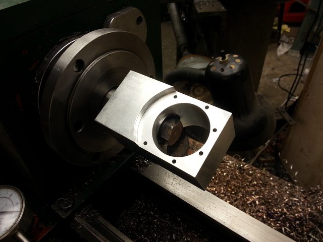
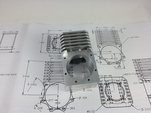
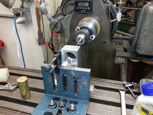
I wanted to install the cylinder liner into the block and turn the fins for something to do while I waited for my bearings to come in for the front cover. Since I didn't want to grab the relatively fragile fins in the vise, I decided to finish the lower end of the block now. Gus showed off using an angle plate, reminding me that I had one. Unfortunately because mine is cheese grade cast iron without a rib to stiffen it, I can push about 0.004" flex at the top of the 5" height. Oh well, it'll be fine for drilling a few bolt holes. Better than my drill press anyway, and better than trying to grab the bottom (top in this case) of a tall skinny object in my cheesy vise. No, that's not the only clamp I used, I'd just taken the clamps off and remembered to grab a picture. The toolmaker's clamp was used as a fence so I could flip the part around and get it close enough for the dial indicator to sweep the bore without much adjustment. On the front of the angle plate I'd stacked parallels and a 123 block so I wouldn't have to dial in the vertical face.


Back to the mandrel. Here's how I did it, after getting an example from a retired machinist family member. Make a 7 degree taper. Make a plug with a matching taper. Bore the start of the hole slightly larger than the thread major diameter, to allow a roll pin to fit in there. Cross drill your bolt for the pin. The pin then pulls the wedge out when you back the bolt out. The bolt head (actually a nut silver soldered onto fine thread rod, but same thing) needed to be turned down a bit, I underestimated how far in the plug would go before locking up on my cylinder. Warning: wobbly hack saw cut!


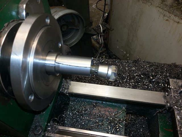
I put a slight amount of tension on the plug, then took a skim down to a perfect sliding fit on my cylinder liner. Then parted the back about half the depth to the counterbored roll pin clearance hole.


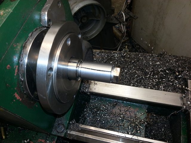
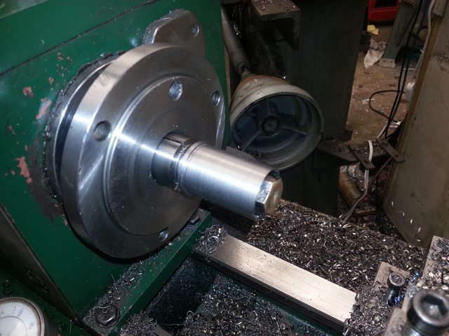
The ends are cleaned up


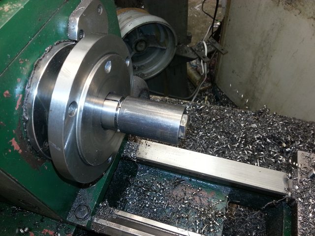
And 0.003" oversize. I was getting tired so I decided to make the final shrink fit dimension the next day when I'd had more sleep and the correct amount of coffee. It'll give it a chance to equalize temperatures too. That 4140 got a little hot from the roughing passes.

 
p.s. if anyone's curious about what a horizontal mill can do that is harder on a vertical mill, imagine facing that angle plate with a fly cutter. You'd need a really deep vise, and one that tolerates an angled part (the angle plate has some draft). Or use another angle plate that's already been proven square and dial it all in horizontal, adding some margin for error.

Such an easy setup on a horizontal mill. I think I'll bolt some ribs to that plate and do just that.
 
I've got an ignition system from an RC gas two stroke, designed to fire once per crank rev. Does this mean I should be running the magnet and sensor off of a camshaft? Or will it work ok if I let it fire every rev and waste a spark at the top of the exhaust stroke?
 
I've got an ignition system from an RC gas two stroke, designed to fire once per crank rev. Does this mean I should be running the magnet and sensor off of a camshaft? Or will it work ok if I let it fire every rev and waste a spark at the top of the exhaust stroke?

On my Nemmet Lynx engine, I have a wasted spark on the exhaust stroke. But, I have 2 magnets set up on the end of the camshaft, this is so the CDI knows how fast the engine is going and can use auto spark advance. If you don't have auto advance, you can get away with one magnet on the camshaft which will only fire on the ignition stroke.

This was all pointed out to me by other members here, they were all so helpfull.

Paul.
 
that's a good point, it's an auto-advance CDI. 2 magnets on a camshaft it is!

Thanks!

That gets me thinking...Maybe I can repurpose the timing belt tensioner for this. Make it 2x the crank pulley and drive it, and stick 2 magnets in it.
 
that's a good point, it's an auto-advance CDI. 2 magnets on a camshaft it is!

Thanks!

That gets me thinking...Maybe I can repurpose the timing belt tensioner for this. Make it 2x the crank pulley and drive it, and stick 2 magnets in it.

If you use the tensioner, just make sure that you can easily adjust the timing.

Paul.
 
Starting to look like my imagination now.

What's for dinner?


Engine block.

Sleeve in


Back on the lathe on the undisturbed mandrel.


Borrowed the wife's lightbox.


yup, slid in easy, and once cool it didn't move a single bit from the fin turning. Thanks for the guidance.
 
darn, I forgot to provide some way for the head to locate on the cylinder bore. I guess I'll use dowel pins or an external fixture for alignment while torquing the head bolts if I don't like the bolt slack. I guess I can always take the liner out and shave a bit off the lip to make a recess for a copper gasket and head location.
 
Last edited:
I took a break from cutting metal and spent a few days modelling more parts of the engine. I've got some questions about where I'm going to mount magnets and sensors for the ignition, so I'm going to make sure I don't need either the front or rear case as a mount point before I start making them. That means I need to plan out the whole head, valves, and camshaft location.

So far I've got a slightly domed head, which took forever to figure out the 90 degree tangent to make the valve guide line up perfectly. Shim over bucket style lash adjustment. .427" diameter valves, and when the port under the valve area is considered, the area matches the inlet and outlet diameters of .321". 0.100" lift gives me 4:1 diameter to lift. The result? Looks About Right, I think. I'll give it a shot.

The CAD program is estimating 1.2 lbs right now. So I'm a little over what a Saito in the same size range weighs, and it'll grow a bit still. This is including a hefty mount though, and saito doesn't include the mount or muffler in their weight spec.


My crankshaft is .472" (funny how that worked out, .427" valve, .472" crankshaft), I might narrow that down after the bearings to cut some weight. It's hollow, so I don't know how much I can gain from that. I'll probably just try it and see what happens.
 
Last edited:
Absolutely. I've been updating the 3d model and drawings to reflect changes as I go. I can't promise the drawings will match drafting standards but at the very least I add dimensions in as I find them missing.
 
  • Like
Reactions: gus
I spent some time with the rest of the head in order to get an idea on valve timing. I decided to copy the Whippet plans i had for the cams and valve timing since it was the same bore, stroke, and RPM target, which means each valve tilted 55 degrees from vertical at TDC to set the timing and a little bit more duration to the exhaust than the intake. Since I had all of the related parts linked together to check that, I made a little animation showing the cycle. After I noticed the exhaust valve collision, I realized the tilted angle of the valves throws off my timing marks. I need to tilt each valve an additional 18 degrees. This means currently, the exhaust cam is 18 degrees delayed and the intake is 18 degrees advanced.

[ame]https://www.youtube.com/watch?v=wH086IyOouw[/ame]

Any ideas how to attach the pulleys to the camshafts? I'm considering broaching a square hole in the pulley and using a bolt and a washer to pull it against a shoulder on the shaft. It's not adjustable that way but I think I can pretty accurately estimate the distance between pulley teeth separated by the belt. I think I'm going to put the ignition magnet wheel on the end of one of the camshafts, sandwiched between the pulley and the camshaft shoulder, but not running on the square. Clamping force from the bolt holding the pulley on should hold the trigger wheel I'm hoping.
 
Last edited:
Nice animation. Is it an optical illusion or is the piston hitting the valve near the top of the stroke?

2-17-2015 0000.jpg
 
Yeah its totally colliding. The timing is off by 15 camshaft degrees or so.
 

Latest posts

Back
Top