First engine, an RC aircraft 4 stroke

Home Model Engine Machinist Forum

Help Support Home Model Engine Machinist Forum:

This site may earn a commission from merchant affiliate links, including eBay, Amazon, and others.


Ok I'm comfortable with how things fit together now. Going this far in CAD before cutting stuff has avoided a few junk parts already, and was worth it. The pulleys were too large and intersecting. Now it's fine. I'm going to start on the front crankcase tomorrow.

 
Last edited:
I managed to forget to get pictures of making the entire front case cover. Sorry!

After turning the front case, I drilled the bolt holes on the mill. I screwed up the setup and didn't have enough range on one axis to drill the last two holes, so I'll get them when I set it up to cut the scallops.


I keep finding uses for the Taig chuck adapter I made for my larger lathe. The soft jaws were just the tool for grabbing on to the thin edge behind the o-ring.

On to the rear case


Drill some holes


Done! (for now)


I'll saw off some of the excess, then set it back up with the boring head set at the right radius and cut those scallops between the bolts by pretending I'm boring a hole.

It's still pretty heavy. I think after I'm done with the crankcase I think I'll put it back on the mandrel and trim off half of the thickness of the cooling fins. At that point there will be no need to clamp on the fins anymore so they won't be structural in any way.
 
Last edited:
Wow that was miserable. Setup to cut the scallops, and the first one I didnt' check surface finish till I was 0.007" from dimension. I needed to sharpen and adjust the angle on the boring bar. Managed to pull it off. Switched to the other side, and I jerked the handle which fed too fast and snagged the rear cover, shearing the corner off and shifting the part on the table. Luckily it only took a corner off that I was going to remove anyway. I dialed it back in, and snagged it again!

Finally, I got both sides cut and called it a night without having to re-make any parts. I should have 1) gotten more sleep and 2) clamped some 123 blocks on either side to add a little more stability to the setup.

 
Last edited:
After giving myself 3 more chances to ruin 30 hours of work, the block is done!


Now I'm going to start on the crankshaft. Thinking about using a ball end mill to cut a groove in it, then a matching groove in the pulley, then using a spring roll pin to lock it in place on the crankshaft, rather than fussing with fitting a square key or some other method of positive engagement.
 
Last edited:
A remastered version of a favorite decade and a half old video game was just released, so I took a break for that. Time to regain my momentum on this project!


Connecting rod time. I decided I needed a connecting rod before a crankshaft because I can't depend on my reamers to give me a specific size. This time was an exception in that they went 0.008 oversize on one hole! I must have hit the bottom of the hole hard or something. Regardless of technique, they seem to be slightly oversize (0.001") and I haven't really figured out by exactly how much. I bought a set of hole gauges to help out with that.

Make a bit of a mess turning some round 7075 into flat 7075, with the bushing bores drilled and reamed.


Large end bushing, 0.0005" larger than the bore. It would have been majorly sloppy if I'd went by the size on the reamer box. Glad I measured. Oilite, but I neglected to read about machining it so I'm sure I've smeared the pores over. It's ok, this will be well lubricated anyway.


Large end bushing shrunk in. I only singed my fingers slightly. Tip: Aluminum at 350F does not look any different than aluminum at room temperature.


Both bushings shrunk in, and flycut to width. Scribe some lines just to keep a track of how close to disaster I'm coming with the next setup


I just need my brain (which I don't seem to be in control of unless I'm almost drifting off to sleep) to finish figuring out how to do the rest of it.

I think this will be the plan. I'll start on the big end intersection between the curved rod end and the flat angled side, with the flat angled side dialed in parallel with a mill axis. Then I'll mill that flat, lock the mill down, rotate the dividing head 256 degrees forming the big end curve, and stop. Then I'll remove from the fixture and swap ends 180 degrees so the little end is concentric with the dividing head, dial the opposite flat parallel with a horizontal axis, cut the opposite side flat, and the small end curve (still to be drawn and number crunched).


Sounds pretty good in my head. I eliminated the dipper, I don't think it'll be necessary and it'll complicate it a lot.
 
Last edited:
Looks like it's working!


Got through making the big end, then I realized two things.

1) I made that drawing not including the bushings, so snapped the lines tangent to the wrong circle. I wanted the bit between the ends to be a little thinner than that, closer to the scribe lines. But it was so easy to get lined up, I'll probably just do it again. The nice thing about the fixture is you can pull the part off to look at it without losing your spot.

2) my DRO started jumping all over the place once I was done with the dividing head for the curved part of the big end. Gotta go in and find the wiring fault. I can make it stop misbehaving with pressure on the cable end, so I'm hopeful I'll be back on track friday.

I'm going to test my bead blasting setup on the connecting rod since it's mostly hidden from view.

Time to readjust those spindle bearings again. Still sneaking up to the ideal clearance.
 
Last edited:
Your solid models are great!! Your pictures are way, way too big. Use a resizing program to post the pictures smaller. If you post them the current size we have to scroll back and forth and up and down just to see one image.---Brian
 
sorry, I didn't realize the forum wasn't resizing the image automatically for everyone. It shows a bar that says "This image has been resized, click this bar to view the full image" for me, and if I click that, I see the full size and can click the bar again to collapse it again. I'll start linking smaller sizes.
 
Your solid models are great!! Your pictures are way, way too big. Use a resizing program to post the pictures smaller. If you post them the current size we have to scroll back and forth and up and down just to see one image.---Brian

Is this size better or still too big? Looks ok on my screen but I don't mind going smaller if the average screen here is smaller.

 
Last edited:
If you post them the current size we have to scroll back and forth and up and down just to see one image

There seems to be a funky forum glitch that causes this for some people on some threads. It happens to me from time to time, and it's always the same threads while others are fine.

As of now, this thread has never caused me an issue - all the pics fit on the screen and have the little 'resize bar' on them. Obviously it's not happening for Brian though.

It's a pain when it happens but I'm not sure we can do anything about it.

Edit to add - the resize bar shows this latest picture to be exactly the same size as previous pics - 1024x768.
 
Last edited:
Yeah I went back and added smaller sizes to them all, hope it helps
 
first major errors today! I quite accurately hit the dimension I held in my head, but unfortunately the dimension was for a different part of the connecting rod, so I cut a flat too far. It had dug into the bearing surface too far to be salvageable, so I decided to start over. I didn't have any 7075 left, so I decided to switch to 6061.

And then something happened that I'm not entirely sure of, maybe I bumped the vise on the drill press. The reamer grabbed the hole it was half into, picked up the vise, swung it all around one rev, and threw the vise across the bench.


I'll run to a friend's place on Monday and grab more 7075. I'll need to order more bearing bronze too, making new bushings will leave me with not quite enough to do the bits that go in the head.

I've got a few fixtures to make for the crankshaft, so I'll start on that while I wait.
 
Last edited:
yes! a friend had enough 7075-T7 (Nice and hard.) to make a pile of connecting rods. With the reamer cut short it runs true. I'll stick it in a collet and keep going.
 
Last edited:
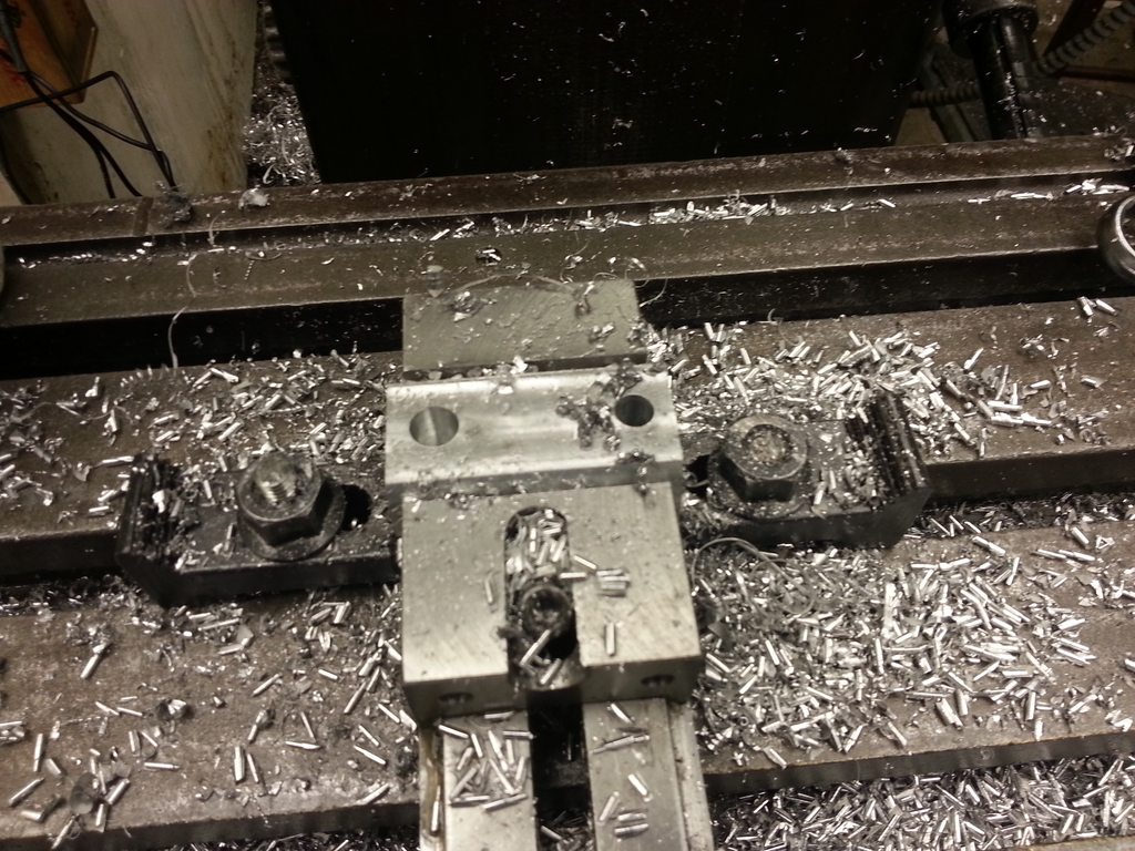
Woo a workable conrod! I had to make 3 of them for the junk bin before I got one that I didn't mill too far into the bearing end. It's nowhere near pretty. It's too difficult to do a rotary table style end with my slow maximum rpms on this mill. Breaking 1/8" endmills all week. if this thing starts up I'll make another conrod with a different method. I think it'll be fine for the troubleshooting step anyway. It at least gets me a reamed press fit hole that I can make a crankshaft for.

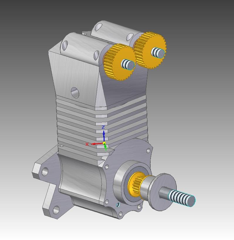
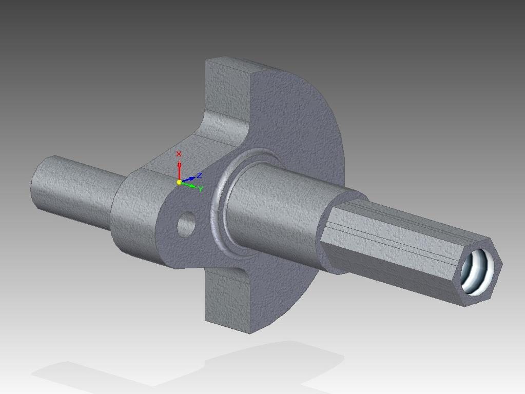
The crankshaft will have a hex to drive the lower timing pulley. Partly because I want to do something a little different, partly because I want to use a pulley so small I can't use a reasonable key, and partly because I wanted to try out the poor man's rotabroach.

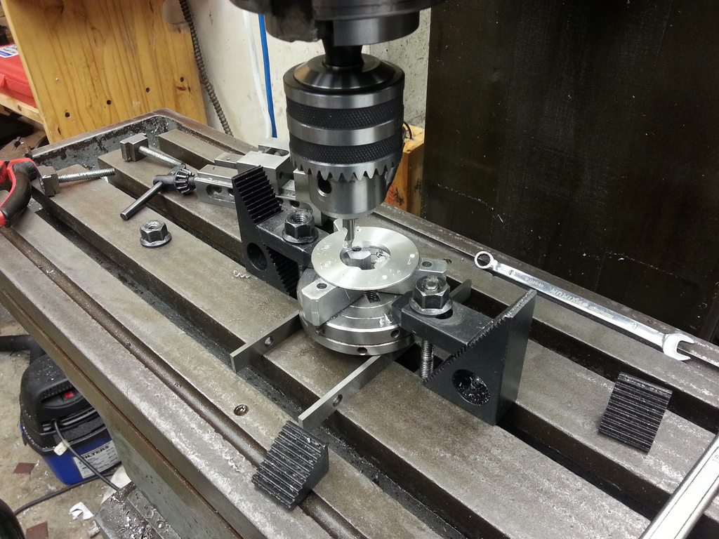
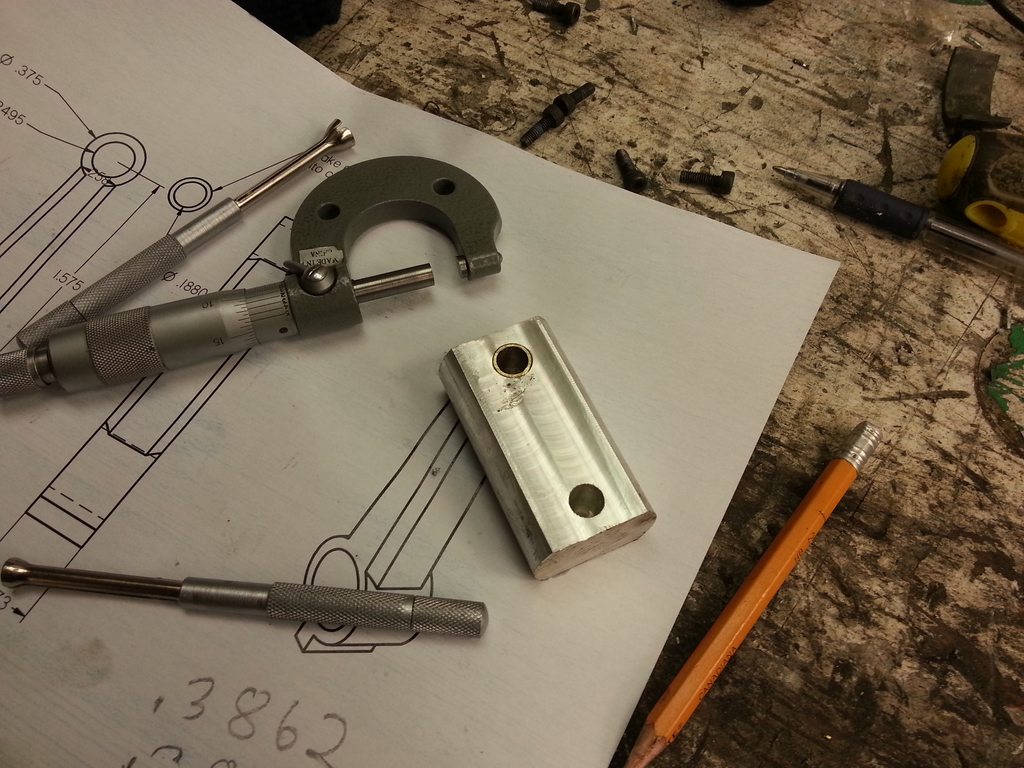
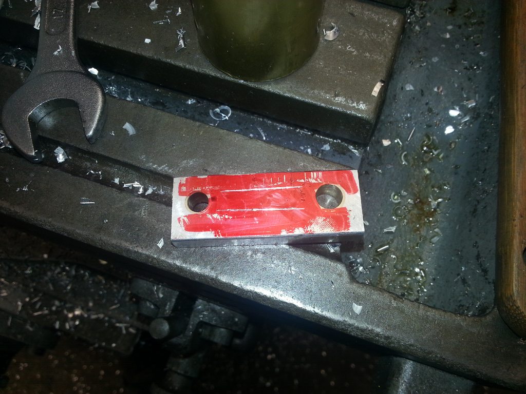
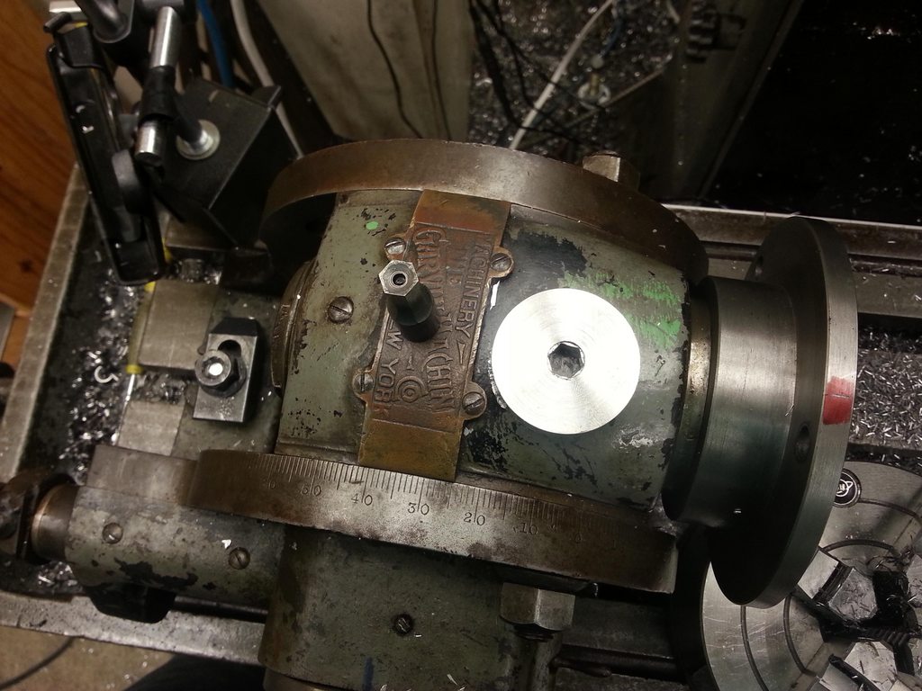
I need to cut a pulley blank before I do the crank, so I can match the crank hex to the hole. That means a hex hole needs to go into a scrap of aluminum. They don't make a rotabroach in the size I need anyway. I saw this method somewhere on the internet, and I have to apologize for the inventor of it, because I can't remember where. Cheap, took me a couple of hours because my milling vise sucks and doesn't like to repeat.

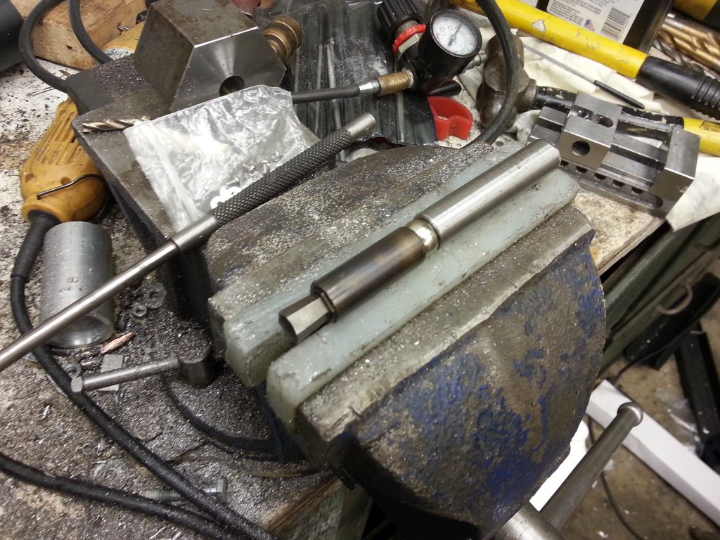
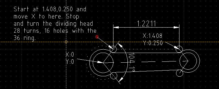
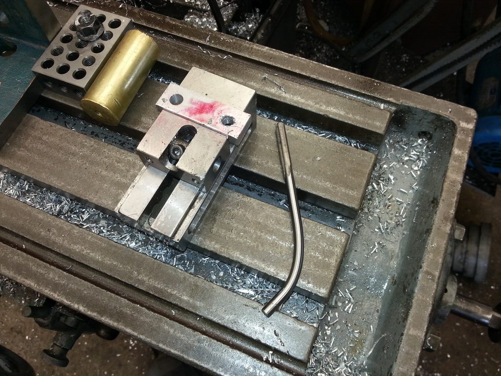
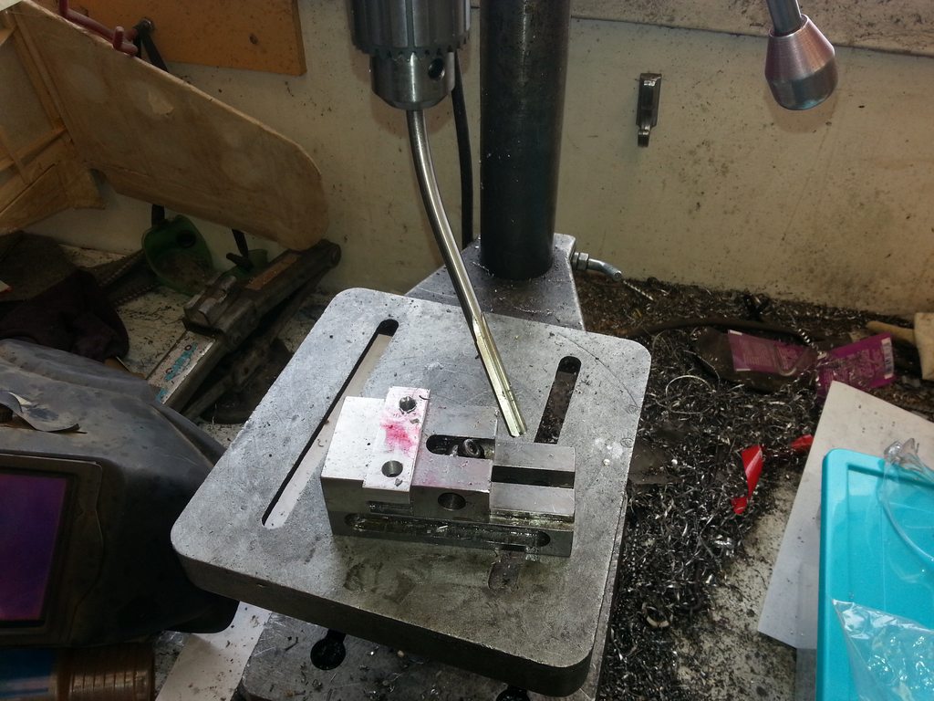
Start out with some drill rod. Mine is 1/2", for the size of hex I was making (.349" across the flats). I used a hex shaped block with a reamed hole and a cross drilled set screw hole to hold it pointing upwards in my milling vise, to cut the flats on it. Cut flats giving the end approximately 7 to 10 degrees relief. Then throw it in a collet in the lathe (or make it run true in the 4 jaw, which ever you like), and dish the end of it. Some prefer to dish the end first, but I didn't like trying to debur the dish after the hex was milled, and prefer to debur flat faces. Flip it around, and drill a deep dish in the other end. I used a large center drill.

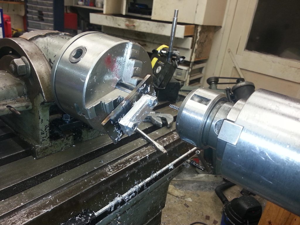
Chuck up another chunk of the same drill rod in the 4 jaw, and offset it about 0.020 TIR (it would probably cut faster at about 0.040, I think there's enough relief on mine to get away with it). Then sink a deep dish with that center drill again in this side.

Harden both as you see fit.

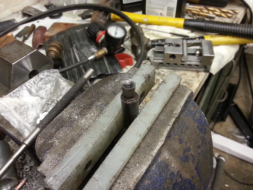
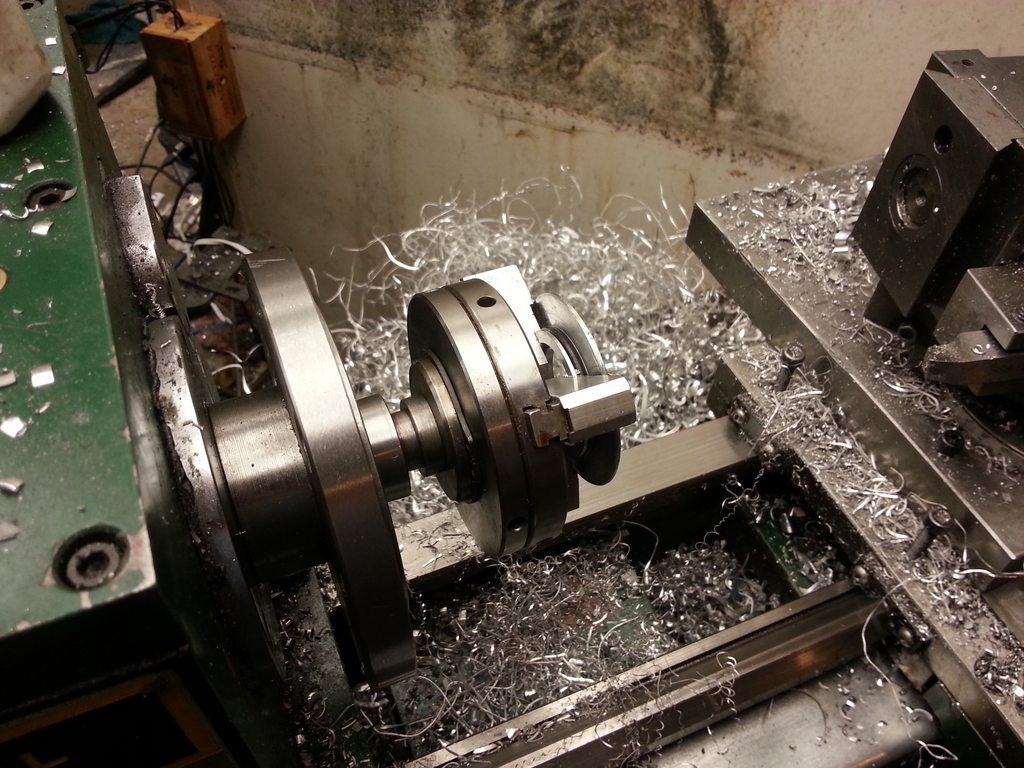
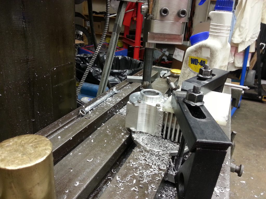
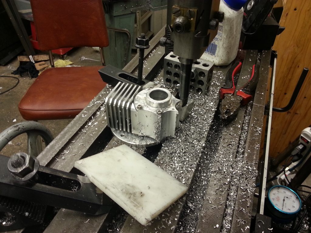
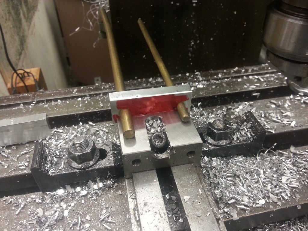
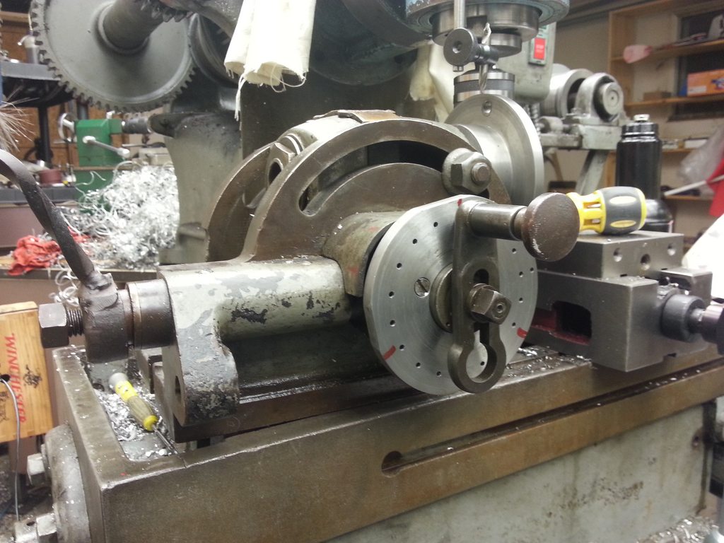
The offset end goes in your drill chuck, and the hex end does the cutting. The ball bearing gets trapped between the two. As the work rotates (or the offset end rotates, whichever machine you're using), the cutting edges of the hexed end take turns pushing forwards a couple of thou at a time. Drill a hole of your flat to flat dimension, or slightly larger. Drill a clearance step of your tip to tip diameter, to allow the hex cutter to start straight. That's a major advantage of a rotabroach, it'll start straight without that step.

Grab a 1/2" ball bearing (or so, was right for mine). Trap the ball bearing between the offset part held in the tailstock chuck, and the opposite end from the cutting edges of the cutting part. Use a high pressure grease on the ball and start the hex end of it in the relief hole. Then hit the gas on the lathe and start advancing the tailstock.

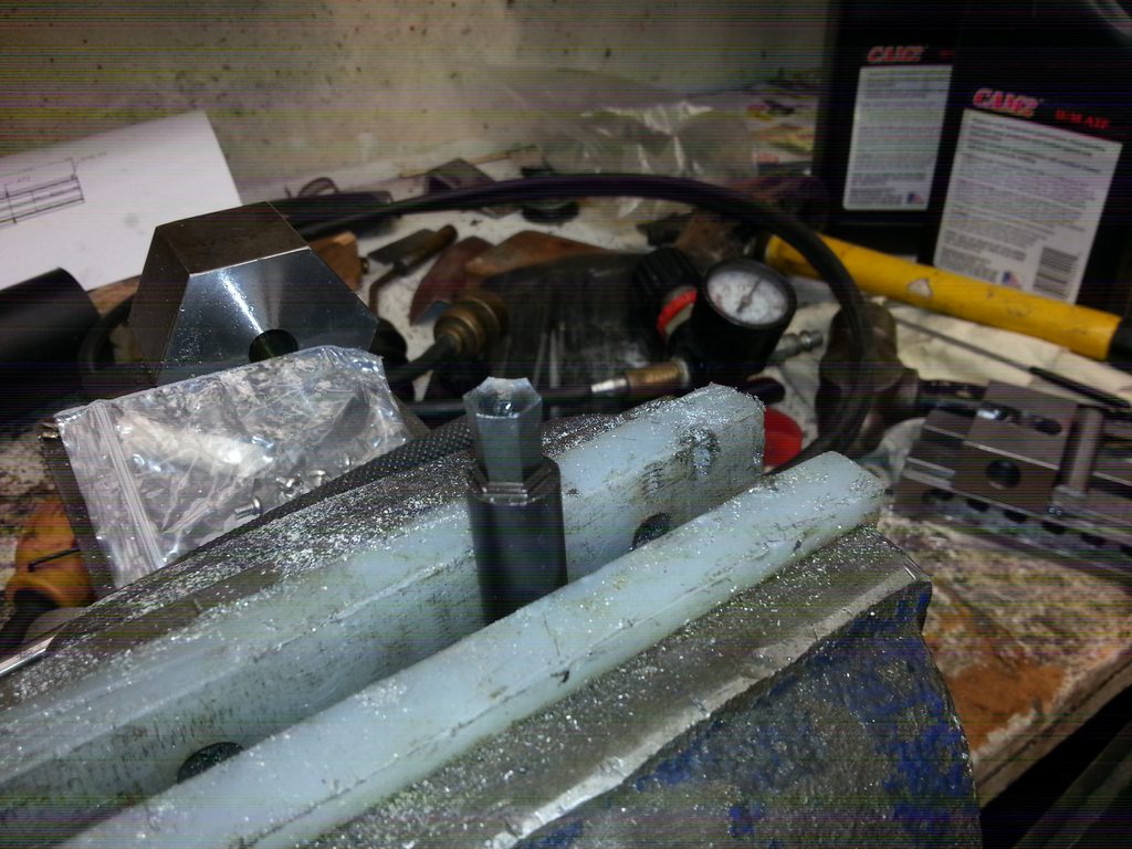
Eventually, it'll cut the corners out. Surprisingly quickly too.


Last edited:
I forgot an important part of making this tool. Rather than bringing the dish on the end right out to the tips, it should be brought to the flats instead, and then using a dremel or a file, file the end relief out to the tips and the flats. It shouldn't have a scalloped edge like the above photo does.

So, 2 more for the junk box, 1 more for me, and I've got a good poor man's rotabroach and a female hex template to assist with the crankshaft. I'll use a carefully threaded 5/16" stud for the prop shaft, because I will be flying it and if I goof up and bend it with an "unexpected landing", I want to replace it easily instead of bending back a shaft.

 
Last edited:
While fiddling with the female hex template I noticed 3 flats were short. Upon measuring, I confirmed that two opposing sides were 0.005" too close and another 2 were slightly too far apart making the hole slightly egg shaped. I realized it was because the reamed hole I'd put into a hex bar as the fixture to index the drill rod wasn't centered well enough. I'd avoided using my dividing head for this task because it didn't have any indexing plates. So I solved that today. I didn't have any 5" plate, but I did have 4". Going with 18 holes allows me to divide 6, 18, and 36, which I'll have to do for this project. I haven't figured out how to make the sector arms work, it seems to be missing pieces. It's easy enough to divide 6 without them though, it always landed on the same 3 holes.


And then it was easy to make an accurate broach.

 
Last edited:
Back
Top