First engine, an RC aircraft 4 stroke

Home Model Engine Machinist Forum

Help Support Home Model Engine Machinist Forum:

This site may earn a commission from merchant affiliate links, including eBay, Amazon, and others.
Well, that dividing head was worth making a plate for. Chucked up a piece of 4140 HTSR on the lathe, turned down the part that will be the hex of the crankshaft, and transferred the chuck to the dividing head. Good fit with the template. I'm happy. It took me all day because I had to true up my chuck adapter on the dividing head.


Now all that's left is all the rest!
 
While I'm busy making a crankshaft, I've started thinking of the cylinder liner ID. I'm used to tapered lapped cylinders for two stroke model engines without piston rings. This is the first engine I've dealt with that has piston rings. I don't have any in my collection to measure. Should the liner still be tapered if I'm going to use piston rings? When the top of the bore expands slightly, the rings will have to spring open slightly. Is this a problem or am I asking for a stress fracture?
 
To the best of my knowledge, liners for ringed 4S model engines should be parallel, not tapered like ring-less 2S. The ring is providing the seal, not the piston/liner squish.The two new OS-4S liners I measured were within 0.0002" (tighter at the top) but that could be manufacturing intention or measurement error. The 4S piston requires annular gap & appropriate allowance for the ring. I'm just embarking on this myself do take it FWIW, but I think there are 2 primary paths:

1) make the liner to your preferred bore dimension, then design the ring & piston dimensions around that. Most refer to the Trimble method or its variations. Lots of web references & this forum. This method also requires a specific ring opening dimension to be 'heat set' so the compressed ring imparts uniform radial pressure. Again, lots of varied opinions & experience on this particular aspect.

2) buy a commercial ring and ideally have access to its liner bore specs & its piston. Target match the liner bore to that & mimic the piston groove dimensions.

Myself, I'm pursuing (2) to avoid (1) for now ;)
I built a spreadsheet using Trimble method just to mess around & check against commercial rings for my own interest. I could punch in your numbers just to give you a reference, but you really need to see the SIC articles to digest what they are saying.

3-26-2015 0001.jpg


3-26-2015 0000.jpg
 
To the best of my knowledge, liners for ringed 4S model engines should be parallel, not tapered like ring-less 2S. The ring is providing the seal, not the piston/liner squish.The two new OS-4S liners I measured were within 0.0002" (tighter at the top) but that could be manufacturing intention or measurement error. The 4S piston requires annular gap & appropriate allowance for the ring. I'm just embarking on this myself do take it FWIW, but I think there are 2 primary paths:

1) make the liner to your preferred bore dimension, then design the ring & piston dimensions around that. Most refer to the Trimble method or its variations. Lots of web references & this forum. This method also requires a specific ring opening dimension to be 'heat set' so the compressed ring imparts uniform radial pressure. Again, lots of varied opinions & experience on this particular aspect.

2) buy a commercial ring and ideally have access to its liner bore specs & its piston. Target match the liner bore to that & mimic the piston groove dimensions.

Myself, I'm pursuing (2) to avoid (1) for now ;)
I built a spreadsheet using Trimble method just to mess around & check against commercial rings for my own interest. I could punch in your numbers just to give you a reference, but you really need to see the SIC articles to digest what they are saying.

Any chance you could share your spreadsheet? Looks like a really handy tool. I'll check if my stack of SIC has those articles.

.0002" sounds to me like a tolerance on a drawing requesting parallel. I'm used to seeing more in the neighborhood of 0.001" per inch on 2 stroke tapered lapped fits.
 
Last edited:
Any chance you could share your spreadsheet? Looks like a really handy tool. I'll check if my stack of SIC has those articles..

Ultimately yes. Right now its a cobbled mess & mostly hard-wired pertaining to my own engine design. So its not quite ready for prime time. I'll be posting some questions to folks already using the Trimble method & thereafter it could be a handy general tool which I'm happy to share.

When you read the SIC articles, you'll see his methodology & his reference to 'being within' 3 constraint curves. That's the part I creatively fudged by 'digitizing' the plot with three y=mx+b intercept equations in order that my own ring parameters could overlay & essentially replicate his plot in Excel. Then I subsequently found another article where the fellow 'computes' the curves from metal input properties which (my understanding) Trimble straight-line simplified. This aspect gets a bit deep & I suspect way overkill. I probably wont go down that path, it was more for personal curiosity.

Anyway, blah-blah. To give you a starting reference, the only thing that's required is the finished bore size. Everything drops out of that. If you tell me your bore, I could just post reply the basic ring results parameters. But as mentioned, you really need to see the original articles to make sense of it. BTW the math itself is dead easy. I was more curious how commercial rings were comparing to this method.
 
It does look pretty easy. I'll go see if I have a copy of those articles and start there. 1" bore if you're curious.

Also, this article was very enlightening for me.

http://modelenginenews.org/techniques/piston_rings.html

I think my plan is going to be follow the trimble method to arrive with a ring with a width 0.002" larger than a ring that would be for my bore, then squeeze it between discs on a mandrel at that 0.002" oversize diameter, and lap it back to my bore diameter so I can be sure of arriving at both the correct wall pressure and the correct diameter.

Have you found any information on oil scraper rings on model engines? I'm probably not going to bother at first, but it's fun to think about.
 
Here's my calcs for 1.000" bore. Don't make anything until you digest the SIC articles! :) Actually, let me know if you derive dimensions other than these in case I have boo-boos.

In terms of oil rings, that's where the article got a bit fuzzy for me. I kind of roughed in what I thought he was doing & left it there because my engine is methanol oil pre-mix, so N/A. There's 2 references I can think of, Terry who built the Hodgson 9 & 18 radials documented here on HMEM. And Rons Offy which used Trimble compression ring methodology so I assume oil control as well. There are probably others too, these are just what I recall.
http://www.ronsmodelengines.com/Offy.html

3-27-2015 0000.jpg
 
A successful, though cosmetically imperfect crankshaft.

I decided that it would be a shame to ruin it after carefully milling a nice hex on it, so I made a little offset fixture to gain a little more purchase and bearing surface than any of my chucks could provide alone, while still avoiding marking the crankshaft. Then I simply dialed in this fixture in the 4 jaw, and turned the crank pin while supporting the end of the crank pin with the tailstock. This worked well.


To mill the crank web cutouts I clamped everything in my vise, then clamped down the v-block so it couldn't move. Then I ran a dial indicator across a rod turned to fit the crankshaft through-hole tightly, necked down to match the crank pin, and compared the reading to the crank pin. I rotated the fixture until they matched.


I got too greedy when milling the balancing cutouts on the crank web, and grabbed. The strength of 4140 prehardened shined, so it sheared the anti-rotation pin and spun the crank around the bearing journal a little ways, without bending the crank and with only minor marking of the surface. I'm primarily a function over form kind of guy, so I'm willing to live with it.


Before rounding off the bit above the crank pin.


After rounding off the crank pin, but off of the fixture for some reason.


And finally, setting up to mill a bit of piston skirt clearance (actually, to hide the marks from the crank web milling gouge, but don't tell anyone ;) )


And bead blast a bit of crap off of it, and the end result.


Last edited:
Some easy quick progress today, but hey, progress is progress. The crankshaft weight was hitting the liner, so I had to make a bit of clearance in the bottom of it. 0.045 off using the boring head and it cleared by 0.010. And an assembly of the parts just for fun.


Temporary mock-up bearings, I'll replace them with one that has a single rubber seal at the front.


Crankshaft and conrod through the rear hole


I should make another connecting rod anyway because it's ugly and easily visible. I haven't quite recovered from the span of time needed to feed 3 connecting rods to the scrap box monster yet though. Maybe next week. I've found a method that looks way easier than I was attempting.
 
  • Like
Reactions: gus
I see how this goes. I'm making a theme of it for this engine. One part for the junk bin, one part for me ;D

Piston #1 is dimensionally perfect! Exactly to my standards, exactly the surface finish I wanted.

I turned the OD, filed and polished it to the correct size, test fit it into the liner, then pulled the chuck off and stuck it on my dividing head as a handy way to hold it, and drill/reamed the wrist pin hole. Then I clamped the chuck down on the table, and using the reamer, indicated it in parallel with the X axis. Then I milled the slot for the connecting rod. After trial fitting the connecting rod, I realized my error. The wrist pin hole is at the exact center of the piece, and at the exact right height, but 90 degrees off from where it should have been. I meant to cut the slot with the Y axis, but I'd used the X axis. Oops!


I'd only wasted an hour and a half with that attempt, I've certainly done worse. 20 minutes and I had another blank turned and ready to try again.

Piston #2 I realized that the horizontal/vertical nature of the mill provided a very handy possibility. I didn't need to indicate anything in except the piston concentric with the vertical spindle. Then I cut the slot first, returning to 0,0 with the DRO. Then I removed the vertical head, stuck the chuck in the horizontal spindle, found the piston skirt edge, moved the knee up to the right spot, and drilled/reamed the wrist pin hole, square to the connecting rod slot within the squareness of the mill.


Sweet! Though, before I took the chuck off the mill I should have cut the crank weight relief. You win some, you lose some. Happy with it overall.

The Trimble calculations tell me I want piston rings of 0.023" thickness. The junk box gods have smiled on me for once, and provided a hacksaw blade of exactly 0.023"! So I spent the weekend making a parting blade holder that takes hacksaw blades.
 
Last edited:
  • Like
Reactions: gus
Here's my hacksaw blade holder


And a piston!


The wrist pin is another shrink fit. I drilled the ends of it for brass pucks just in case the shrink fit temperature is exceeded during running and the wrist pin slips. I've ruined a two stroke liner with a wrist pin I thought was a secure press fit but it moved with heat.
 
What are the relevant dimensions (target and/or actual), and how will you assemble?
(My next job is gudgeon pin bores in pistons.)

I installed the pin just after that photo. It was kind of a feel thing rather than checking bore sizes, but I've worked with that size of fit in aluminium fairly often. I was working around the reamers that I had. The connecting rod bore was .251, the piston pin bore reamer was .249. I polished the pin until it fit with a tiny bit of slack in the connecting rod, but still didn't quite fit in the piston bore, so it was between .251 and .249, and measured .250 with a micrometer of unknown accuracy. I was targeting 0.001" over the bore size, and assuming it wouldn't just drop in once heated, and that I'd need to add a bit of force from a punch. I gave it a generous chamfer on both ends and center drilled both ends to take brass pieces. A light tap with a brass block felt like it would probably make it go in if I hit it harder but I wanted to be as sure as I could that I didn't upset any material that could work the hole looser later on and I didn't want to mar the finish on the piston.

I polished about 1/8" of one end of it so that the end would fit into the piston pin bore without me having to hold a hot pin, hold the torch, hold the hot connecting rod, and hold the hot piston while trying to tap it in, and also so that it would be less likely to raise and push aluminum ahead of it when I tried the next step. Then I went over to my bench vise, that had soft acetal jaws installed, and tried to push it in a little further using the vise. It was relatively easy to do, no threat of bending anything and not requiring excessive force, so I knew I was in the ballpark. The pin was installed about 1/4" of it's 0.8" length at that point. I could have pressed it in the whole way like this, but I was concerned about distorting the piston with the vise and then setting it into that distorted position by the force of the press fit. I thought that reducing clearance on the already tight slot was to be avoided at all costs so the connecting rod would be free to move. The original plan was a heat shrunk fit anyway, so I continued with that plan.

I clamped a low-precision v-block into the vise, one that I didn't care if it was heated up a little bit. I placed the piston into the v-block so the pin hole was vertical with the slightly-pressed-in pin pointing upwards, and the connecting rod hole aligned with the pin by looking through the opposite hole. The connecting rod bearing has a generous chamfer on it to help it self-align during this step.

Then I heated the piston with a plumbers propane torch until the part of the pin that was sitting in the piston began to show a light straw colour, and began tapping the pin down with a brass pin punch I had on hand. I didn't need a hammer or any other kind of striking tool, the weight of the 1/4x4" punch (with a tapered nose) by itself was enough. I kept tapping it down until it was just beginning to enter the connecting rod. Then I wiggled the rod to center it and free it up, then kept tapping and flipping it over by the connecting rod to check the progress until I was happy with it. I didn't need to re-apply heat, the job was over faster than I could type this.

One brass piece on the end of the wrist pin was a nice press fit and stayed in during the whole process, the other needed to be loctite'ed in, and popped out when I started heating it. I just reinstalled it with loctite when it was cool.

I'm glad I'd put an oil hole in the end of the connecting rod. The sides were such a close fit with the slot in the piston that I'm pretty sure next to no oil will get in that way. The second I splashed a bit of oil into the piston so it fell into the chamfered hole at the top of the rod, it all freed up nicely.
 
Last edited:
The heat was likely overkill. With the slight taper on the tip 1/8", and finely polished, I think it would have been no problem to press it in. If it bound up the connecting rod I could have tapped it back the other way a bit to clear it. It was shocking how much of a reduction in required pressure there was though. Totally took the risk of breaking something with a hammer right out of the equation.
 
Hi Chris,
Wanted to DIY Saw Blade PArting Tool long time ago.Was procrastinating as I have never seen one working well.Thanks for the post. Will copycat. Beats re-inventing.

Have some regret using split pin to secure Rocker Arm/Clevis Pivot Pins and it does not look as good as using ''E'' Clips. Might just turn around and DIY same Parting Tool to cut Groove for ''E'' Clips. M.I.C. ''E'' Clips tend to open. Best to use M.I.J. Clips. Will beg/borrow/steal some from the fishing equipment shop.
Jerry Howell's V-2 prints called for ''E'' Clips and Gus deviated.

IMG_3312.jpg
 
Last edited:
Hi Chris,
Wanted to DIY Saw Blade PArting Tool long time ago.Was procrastinating as I have never seen one working well.Thanks for the post. Will copycat. Beats re-inventing.

Have some regret using split pin to secure Rocker Arm/Clevis Pivot Pins and it does look as good as using ''E'' Clips. Might just turn around and DIY same Parting Tool to cut Groove for ''E'' Clips. M.I.C. ''E'' Clips tend to open. Best to use M.I.J. Clips. Will beg/borrow/steal some from the fishing equipment shop.
Jerry Howell's V-2 prints called for ''E'' Clips and Gus deviated.

Gus,

Forgive the messy drawing, but I measured up mine. Here's what I made (inch units). Absolutely none of these dimensions are critical, make it to whatever you've got on hand. Designed to fit a tool post that takes 3/8" tool bits, but I made no effort to make the hacksaw blade on-center with the lathe axis as I've got a quick change tool post. My junk box is full of 1/2" tall hacksaw blades. I had a dovetail cutter so I made the 60 degree angles in order to pull the blade into the vertical surface. (drawing attached).

Edit: just tap the clamp bolt holes before milling the relief on the bottom surface as the holes intersect the vertical portion of that relief.

View attachment parting blade holder.pdf
 
Last edited:
Hi Chris,

Thanks. Drawing stored into ''' Tools to Make''. In future ''E'' clips will be used to secure pivot pins. Now looking for good clips. The M.I.C. clips ''no can do'' as they have very poor holding power and tends to open up.
 
A few things have been delaying this project.

1) I needed to make some tools to radius the under side of the head
2) It's summer and I own a motorcycle

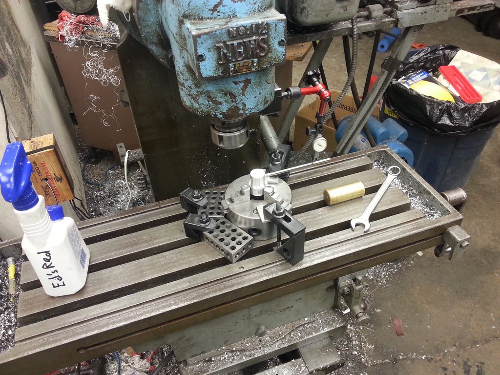
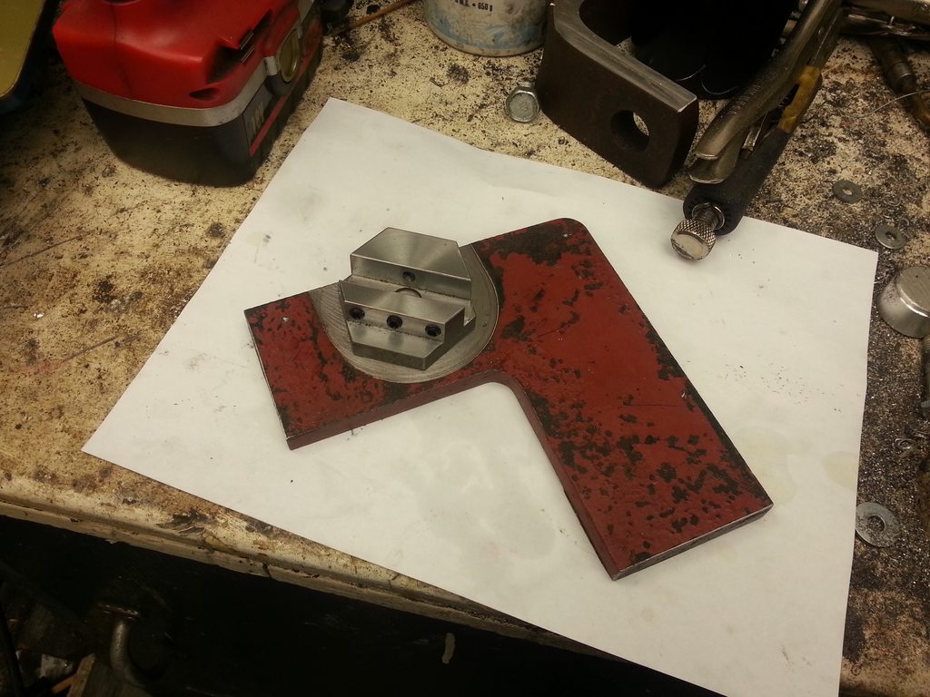
But I've made a little progress on a radius tool. I wanted to make it fit many types of jobs, so I needed a lot of adjustability and the ability to turn concave as well as convex radiuses.

I got this idea from somewhere else on this forum, but I don't remember where. Apologies! In any case, I can't take credit for it, I only modified the idea for the bearing.


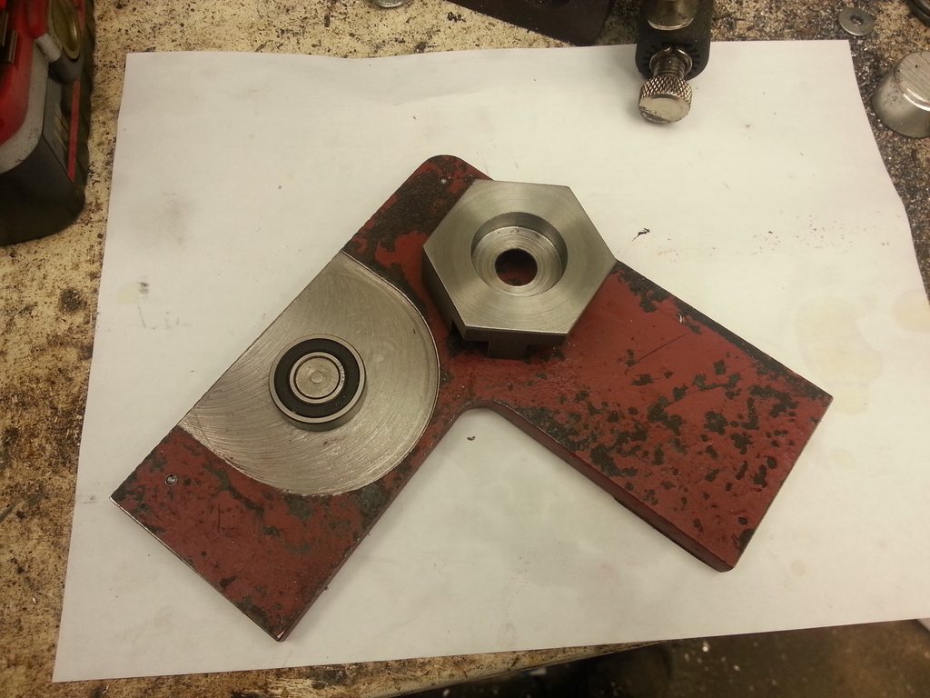
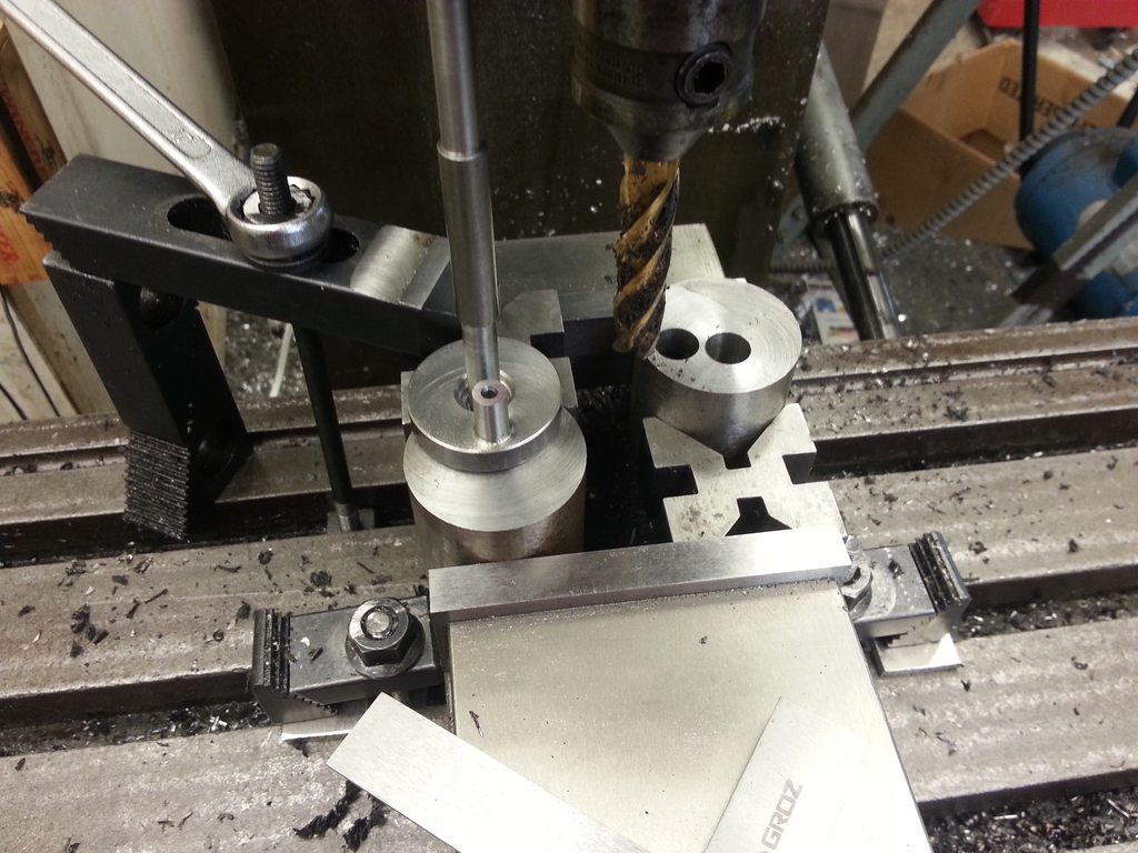
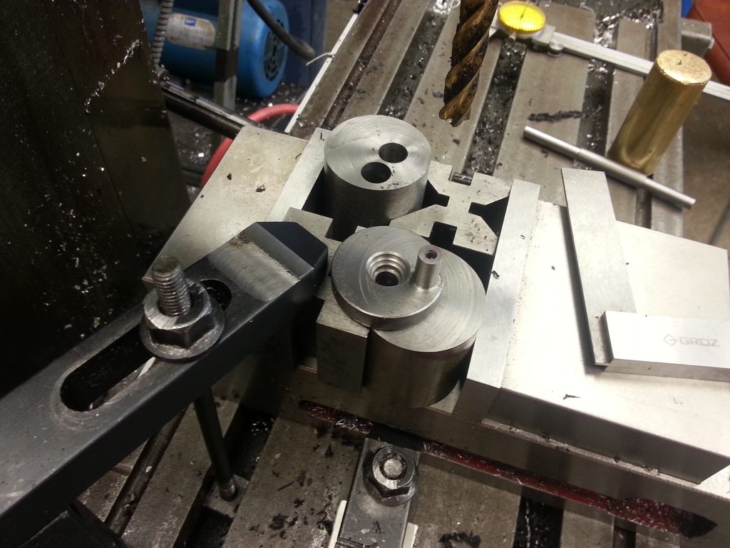
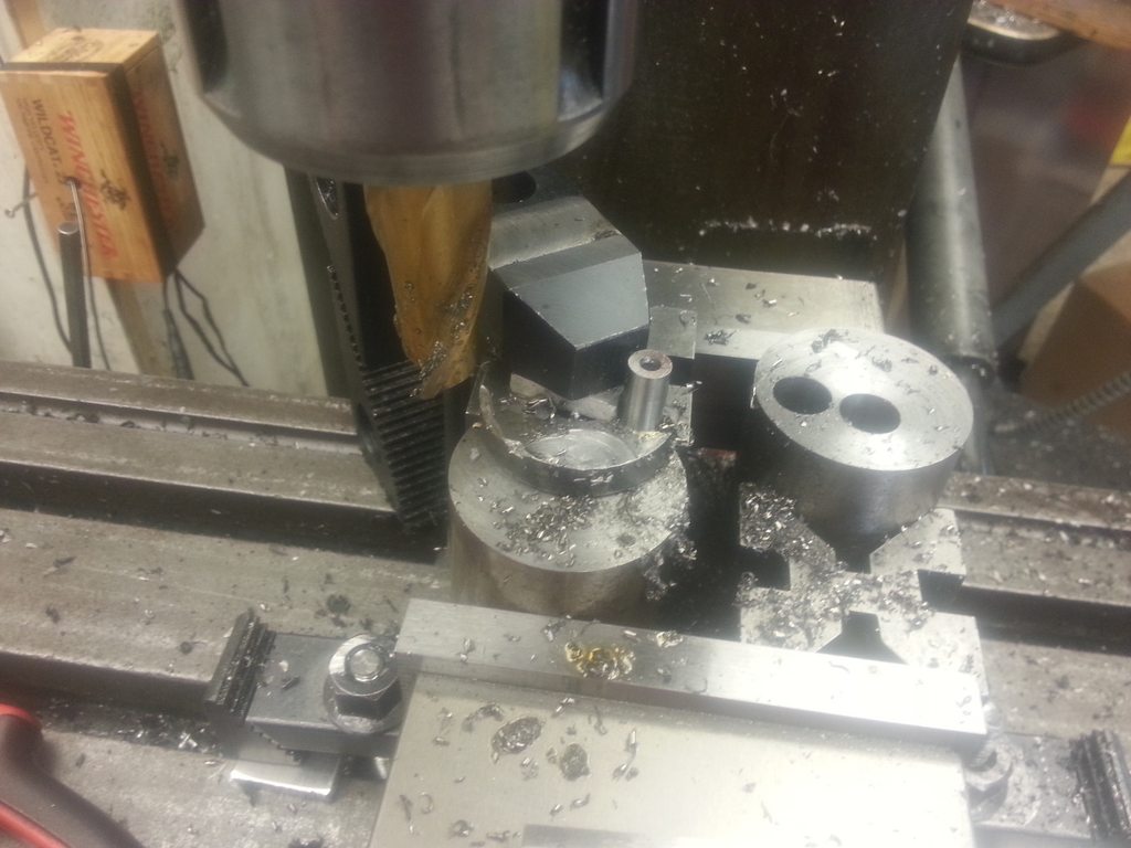
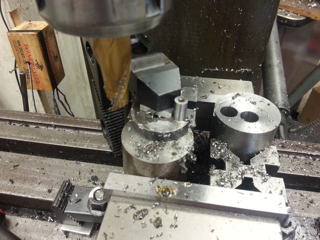
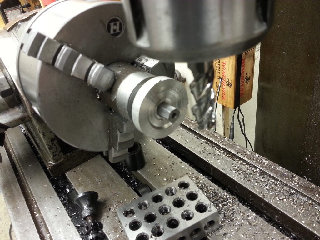
I didn't finish the whole top because it's some nasty very hard tractor parts that is cold rolled and warps like a banana. I did the top first, then flipped it over and cut some clearance on the bottom so I had 3 pads I could finish, instead of doing a finish cut over the whole surface. It worked well enough but my surface finish isn't great. It'll work fine. Pressed in a stud, pressed on a bearing, and had a wiggle-fit for the bearing into the under side of the tool arm holder. I loctite'd the block to the bearing.


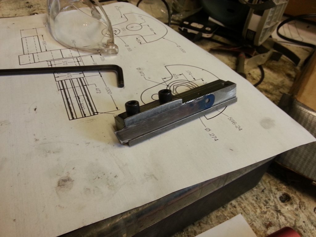
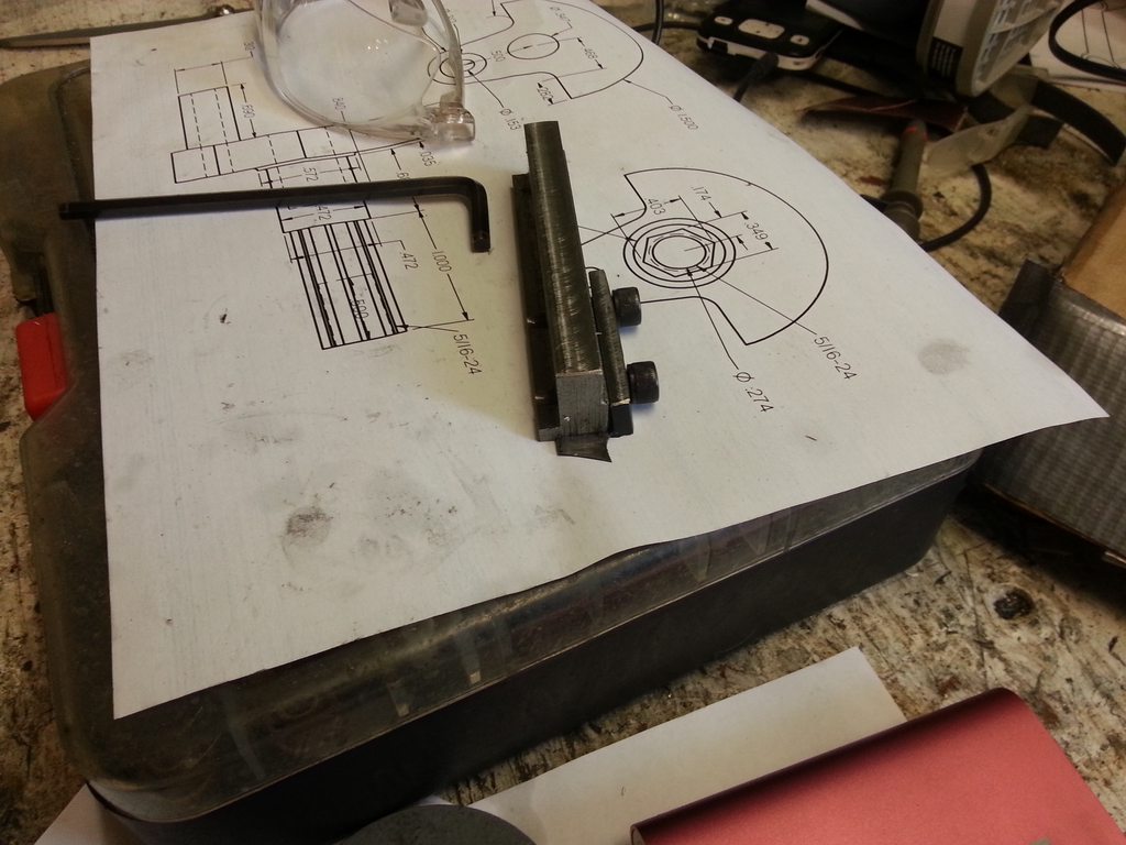
1/2" slot 1/2" deep right down the center, and some clearance for set screws. This sets the radius of the curve. The slot is about 0.025" wider than 1/2", so when using 1/2" material, I could have a feeler gauge shim that the set screws would bite into, instead of biting into the arm and causing problems when trying to make tiny adjustments.


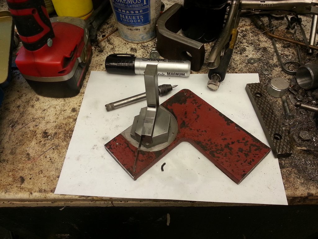
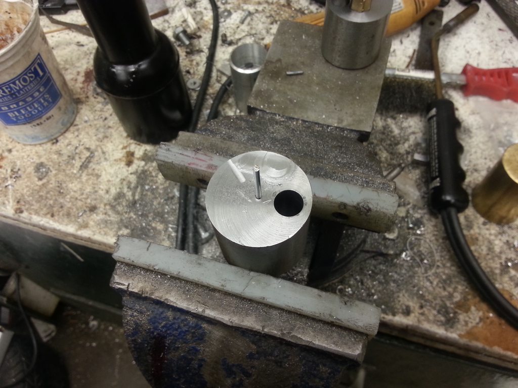
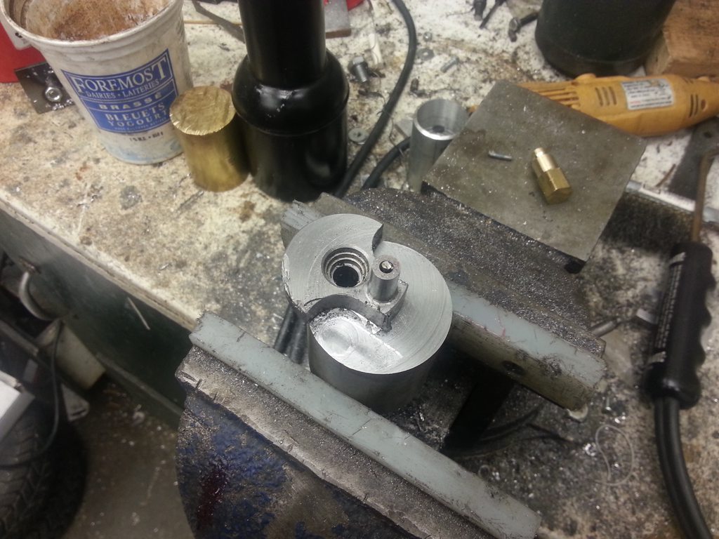
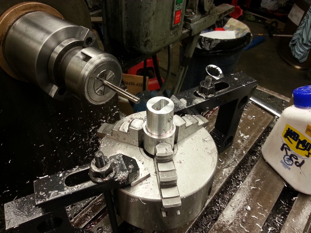
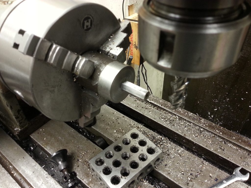
The tool bit holder arm in place. I brought it to the lathe, stuck a scriber in the spindle, and scratched where the tool bit would go, and drilled/reamed a 3/8" hole at that location. Then I drilled and tapped from the top, to insert a set screw.

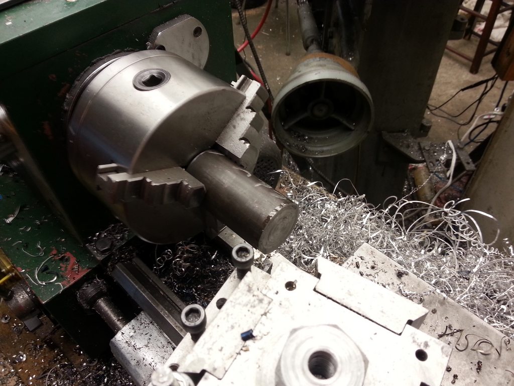
I just grind toolbits from broken 3/8" endmills. Flip the tool bit end for end to switch between concave and convex radii. The whole mess bolts down to the cross slide of my lathe with the compound removed.

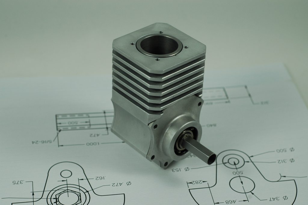
Next I'll consider order of operations to make the head. Probably going to go something like this:

  • Bring a block to size, but about 3/4" taller than it needs to be.
  • Hold it in the lathe 4 jaw, and turn the corners.
  • Turn the concave under side.
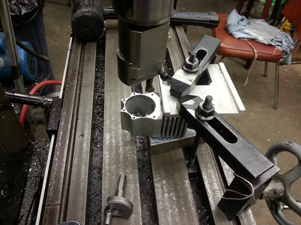
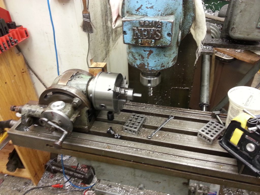
  • Remove from lathe, and bolt down to the mill table piston-side down, with the mill in horizontal mode. Indicating off of the table and the edge of the part, drill/ream the camshaft bearing locations.
  • Reinstall the vertical head, and drill/counterbore the head hold down bolt holes.
  • Remove the head and make a fixture that sits at the correct angle and has a register for the ring on the under side of the head, as well as 4 threaded holes.
  • Bolt the head to the fixture, and fly cut the angled top of the head (which will be located at the centerline of the camshaft holes).
  • While still in the fixture, mill the pockets for the valve train to fit inside, and drill/ream the valve guide and seat hole.
  • Flip the head 180 degrees and repeat on the other side.
  • Flip the head 90 degrees and complete the spark plug hole features.

The trickiest part is figuring out how to locate the features based on the edges of the tilted head block. I may have to get CAD involved so I can indicate off of known locations of the fixture instead.

Enough stuff to do that it may stretch throughout the summer months.
 
Last edited:
  • Like
Reactions: gus

Latest posts

Back
Top