Philip Duclos "Odds N Ends" hit and miss engine

Home Model Engine Machinist Forum

Help Support Home Model Engine Machinist Forum:

This site may earn a commission from merchant affiliate links, including eBay, Amazon, and others.
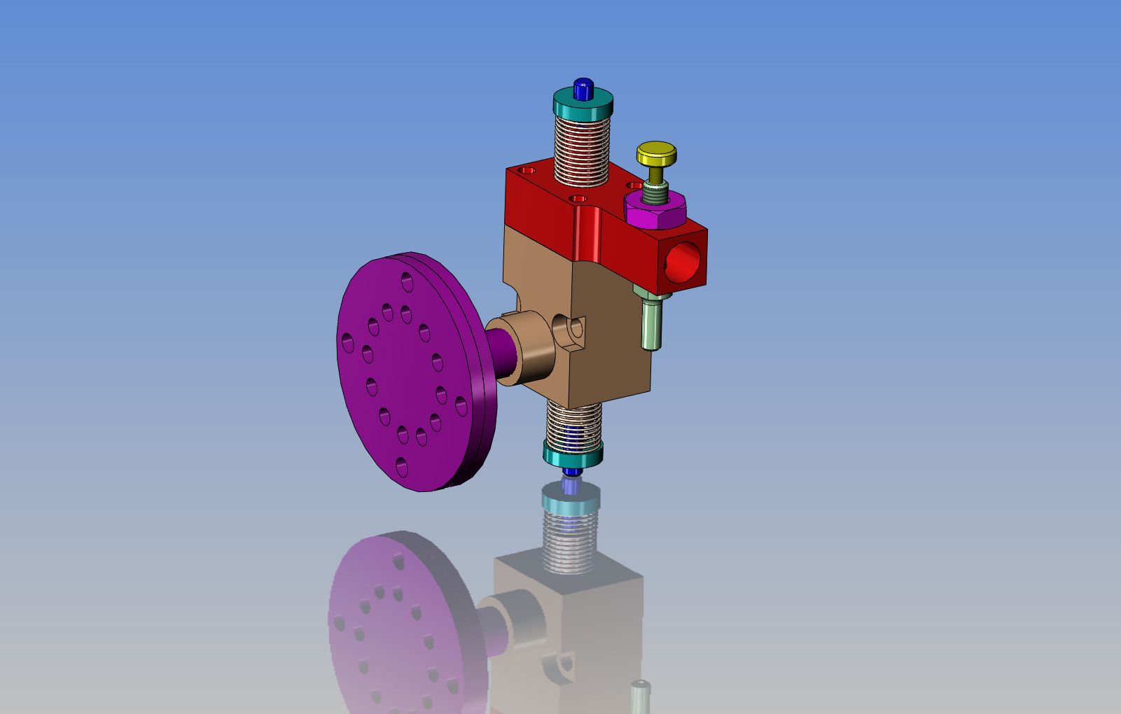
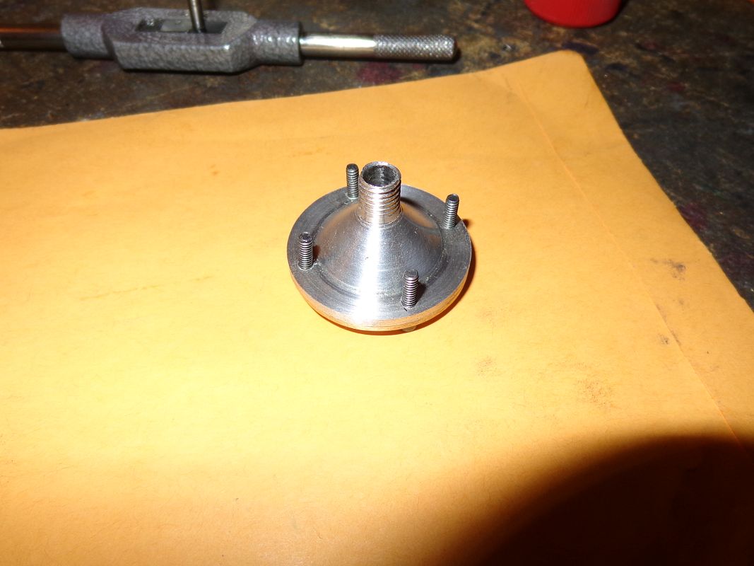
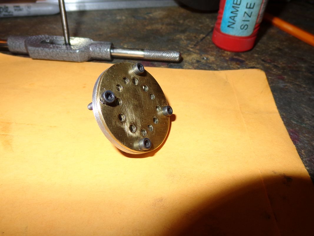
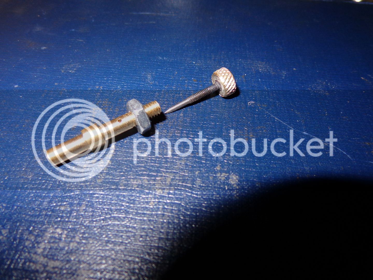
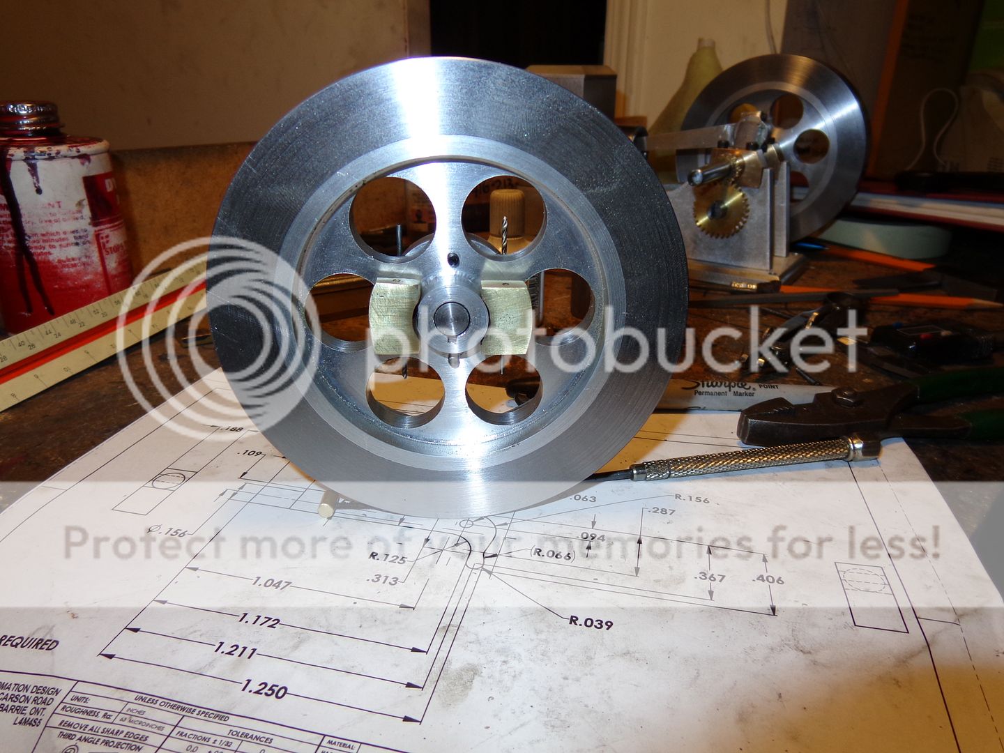
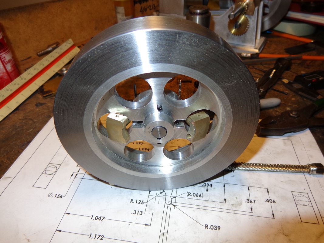
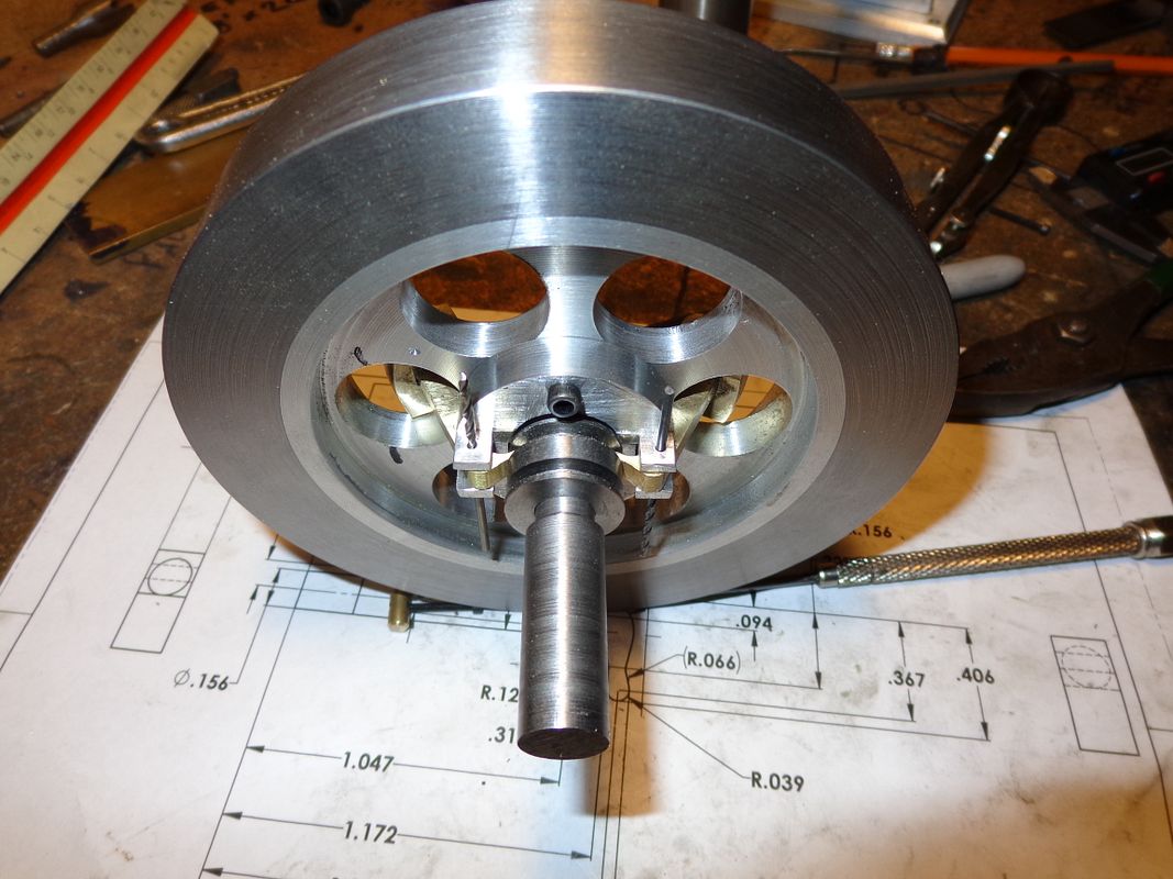
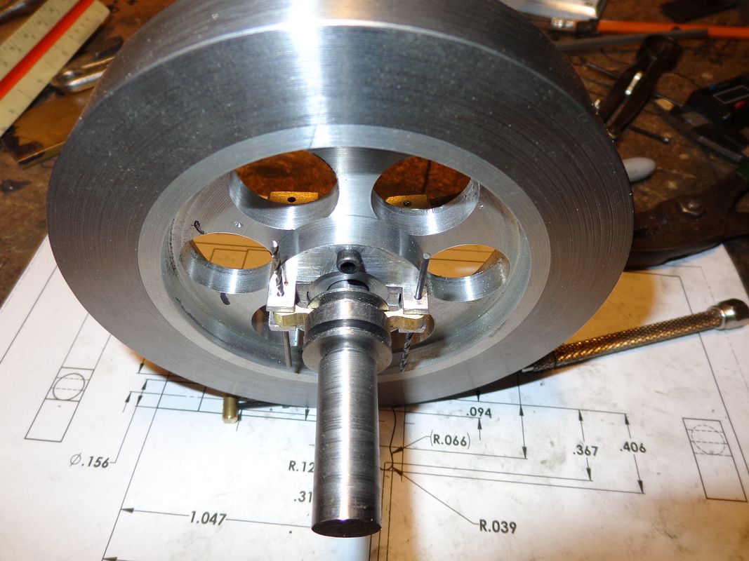
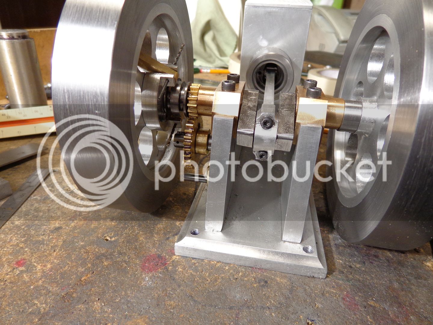
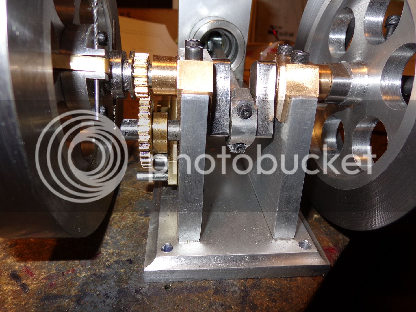
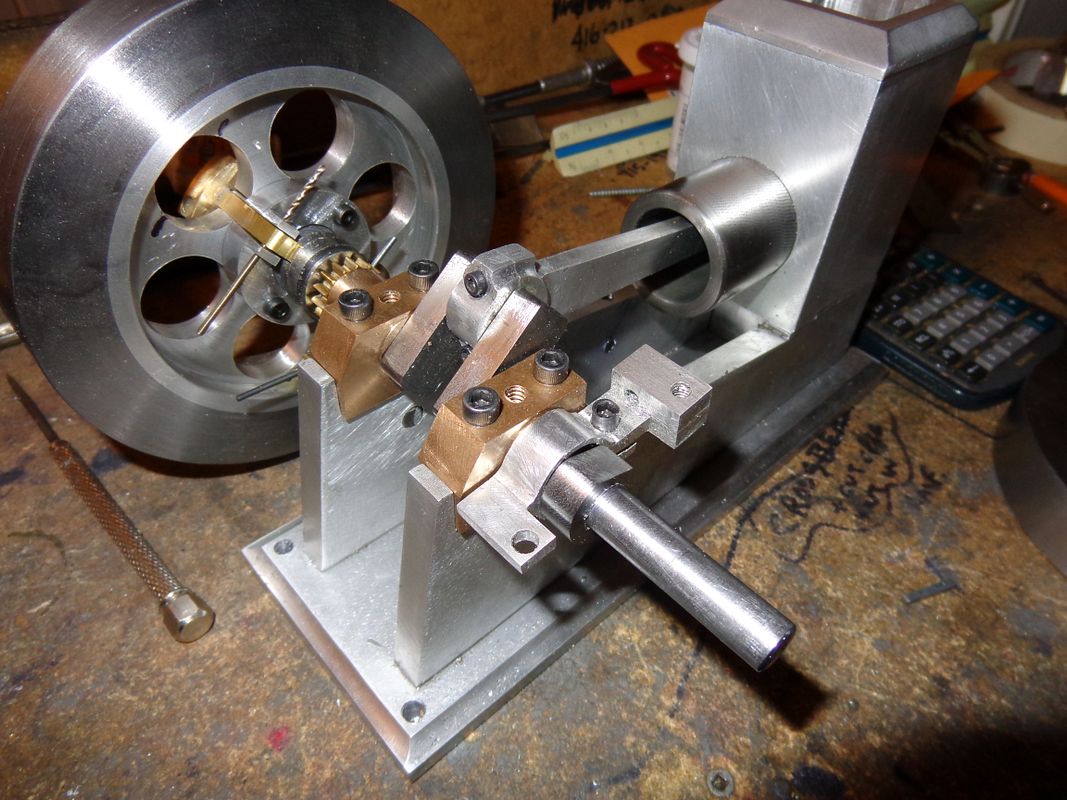
This was an afternoon of mucking about with itsy bitsy pieces. I managed to get everything silver soldered together without too much mess, then cleaned up and fitted/installed. I have shown the governor weights and arms at both maximum amnd minimum travel, from both sides of the flywheel. That spool that the ends of the arms engage in slides back and forth about a total of 5/32" on the crankshaft. The other slot in the spool is where the lockout arm for the exhaust valve fits into. The tension springs which hold the weights in the closed position are not yet installed, but you can see the #2-56 tapped holes in the sides of the weights..
GOVWEIGHTSINSTALLED001_zps0b2ddc2b.jpg

GOVWEIGHTSINSTALLED002_zps2b8938e0.jpg

GOVWEIGHTSINSTALLED003_zps2f9ff703.jpg

GOVWEIGHTSINSTALLED004_zps12b2ff85.jpg
 
The name of the game today, was Rocker Arm!!! I love the look of brass on an engine, for the contrast, and I find it lovely stuff to machine. I only dislike brass when I have to BUY it. Fortunately there were enough left over bits and bobs in my brass drawer to make up the two piece rocker arm, and a couple of bits of 3/16" cold rolled, one for the pivot shaft, and one silver soldered to the rear rocker arm for the governor latch lever to interact with. I still have to make a very small cam follower wheel that is attached to the end of the rocker arm that hides in behind the flywheel.
ROCKERARMS006_zpsffafb1ab.jpg

ROCKERARMS007_zps002d9901.jpg
 
This morning, after some rather "delicate" work, I made up the steel cam follower and shoulder bolt. You can see the cam follower in contact with the single cam lobe in one picture. I chickened out on making the shoulder bolt---simply too small for me. I cheated by machining the correct size of shoulder (.156" diameter), drilling it 0.109", and loctiting it onto a #4-40 socket head cap screw. The cam follower seems to turn freely by finger pressure. I have also included a picture of the rocker arm with the cam follower and governor latch post assembled to it. Now----I am in deep doo doo. Last fall we recarpeted the entire house, including the stairs which lead upstairs from my basement workshop. We were smart enough to use an industrial type carpet on the stairs, which was a close color match with the carpet in the rest of the house. Over the course of the winter, I have made so many trips up and down the stairs that there are two very distinct "tracks" up the carpeted stairway that correspond perfectly to my shoes---and the cutting oil which has clung to the bottom of them. Yesterday I hand cleaned the stairs with an industrial cleaner. This morning I cleaned the stairs again with some kind of powder which is gauranteed to pick up oil residue from carpet fibers.---and it worked quite well. Now I am off to the shoe store to buy a pair of slip on "toe rubbers" to wear over my shoes when I'm in my shop. Wife still loves me, but it was a close thing!!!
camfollower001_zps2c6509eb.jpg

camfollower-2001_zps73f02db1.jpg
.
 
I made two of these little rascals this evening. The one closest to the detail drawing was made first. I didn't think it was quite good enough, so I made a second one. (farthest away)-----It turned out worse!!! To be truthfull, I am not good at these tiny parts with complex shapes. The only good thing about it is that these little engines are very foregiving.
GOVERNORPAWL004_zpsb8599492.jpg
 
Brian,
I know you keeping hoping to find some work, but forgive me if I say I enjoy it when you are "bored". You turn out some great model engineering and I really appreciate the effort you put into documenting it.

Pat
 
Thanks Pat. I really didn't want to build this engine, but boredome is a terrible thing. I realized today that I don't have a great deal left to do on this engine. Tomorrow I will probably build the ignition point set up, and then basicaly all thats left is the bolt on block which consists of the carburetor, muffler, intake and exhaust valve module. This will probably take me into mid March. I'm glad you are enjoying the build, and I'm glad you stopped by and said Hi. One of the problems with documenting a build this thoroughly is that by the time you've got to the 13th or 14th page, nobody stops and says Hello. I know people still look at it every day, because the "view counter" keeps going up. Between this forum and the other forum I post on, about 23,000 people have clicked on it and had a peek.
 
Looks like you are in the home stretch, Brian. It's getting exciting!

By the way, if you need to make some adjustments to the shape of the little levers you made, you can always heat them up red hot and bend them a little one way or the other. That's what I had to do on mine.

Chuck
 
Hi Brian I have been spending a little time in the shop ( don't tell the Dr. ). I'm working on the crank now a little each day. It's good to be back even if it's a little. Keep up the good work. I am learning a lot from your build. Ed
 
My 1" diameter cast iron rings from Coles Power Models came in the mail today, for what I consider a very reasonable price. This will be a first for me, as far as model engines are concerned. My only experience with rings comes from building engines for the hotrods I used to race. I clearly remember how little you have to deflect one of these rings, trying to install it on a piston, and SNAP---broken ring!!! Certainly hope that doesn't happen here. As some guidelines for the ring groove in the piston, Philip Duclos recomends that the ring groove be .0005 wider than the ring thickness, and the depth of groove should be .002" deeper than the thickness of the ring, in the book section about the Odds and Ends engine. Then in his section about making your own piston rings, he recommends an end gap of .004" when the ring is setting squarely in the cylinder. Do you experienced engine builders concurr with that? The bore on my engine is1.00".
CASTIRONRINGS001_zps25e4e8d1.jpg
 
And here is the part which I hope with all of the sincerity in my black old heart becomes the basis for a workable ignition point set up. (just inboard of the ignition cam). I still have to add a piece of spring steel and an insulating bushing. Philip Duclos recommends using a section of broken hacksaw blade!!! Some people that have built this engine say that it works great. Some people say it only works with modifications, and some say it don't work at all. I know that the material cost nothing but the machining has just eaten up 5 hours out of my day. I will post a picture when I get all the small bits added to it.
ignitionpointfixture001_zps131127dd.jpg
 
Hi Brian,
Fantastic build as usual from you, a pleasure to follow along. From past memory those ring specs. look right, 3.875 bore chevy was about .015" gap, thats close to .004" per 1" scratch.gif
Cheers
Terry
 
Here is a video you will find interesting. It concerns the "home made" ignition points on the Odds and Ends engine.---Brian
 
I just destroyed a 3/8 end mill, a 1/2" endmill, and a 1/4" brazed carbide boring bar---trying to open up a piece of brass!! I had one of those halogen lamps with the polished brass 1" dia tube stand. There were pieces of cast brass in the ends, and I tried to salvage one of the castings to make a cylinder oil cup. I don't know what on earth is in that piece of casting, but the damned thing must be harder than a diamond. It has now cost me more in tooling than if I had just went and bought a 12" length of 3/4" brass!!! Some days-------
 
Hi Brian, nice video, points look fine to me for this sort of thing (your not expecting to do 25000 miles a year with it) no reason why it wont work and is certainly an easy way to adjust the timing. Sorry to hear about your endmills :eek: sometimes I think that breaking endmills must be what I set out to do for the day :mad:
Cheers
Terry
 
I'm getting down to the nitty gritty here, and I have ran out of brass----almost. I had enough of a 3/16" brass flatbar to cut the round muffler baffle out of, and drill it on the mill, using the rotary table. Then I thought I would be smart, and attempt to mill it down to the required .093" final thickness, in the rotary table, with an endmill. That never works for me!! Oh, it mills it down all right, but it leaves "tracks" all over the surface, and no matter how hard I try, I can never get all of the "depths of cut" to come out exactly the same. What to do, what to do. Then I remembered all the postings I had seen on here about "glue chucks". Okay, using what i currently have in my arsenal, I will create a "glue chuck". I had a short piece of 1.5" diameter cast iron x about 1 1/2" long setting around. I had some epoxy glue.---YES!!! Epoxy the brass disc to the face of the cast iron. When the epoxy sets, I will chuck the cast iron in the lathe chuck, and taking light cuts with a sharp hss cutter, final finish the face of the brass part in the lathe. Then break it away from the epoxy with a little heat, then dissolve the remaining epoxy with laquer thinners. Will it work?? I'll know later today. The model shows the baffle with the holes (its purple). The picture shows the part setting on the lip of my micro furnace, setting up the epoxy.
CARBURETOR-SUBASSEMBLY_zps220c727e.jpg

MUFFLERBAFFLE001_zpsdbe07acd.jpg
 
Hey!!! This glue chuck idea really works well!!! Of course, if I was smart, I'd have done it BEFORE I drilled all the holes. However, its something new that I hadn't tried before, and it does work remarkably well for thinning down stock which is already too thin to hold properly in a conventional chuck. I am very happy with the results, and will file this idea away for future use. The nice thing about it is that the stock being thinned doesn't have to be round. It can be any profile, simply glued to the end of a piece of round stock.---Brian
gluechuck001_zps495ceda4.jpg

gluechuck002_zpsc7446a4e.jpg
 
Well Sir!!! I survived a massive two grandchild birthday party today, and still had time to whittle out a muffler after everybody went home. Oh, I know, the screws have to be shortened, and the brass need some more polishing, but the machining per se' is done on that item. There isn't too much more I can do untill I part with some of the Rupnow gold and buy some brass for all the carburetor bits. That muffler is a really tricky bugger to machine. You get to a point no matter which way you approach it where there is nothing to hang onto for the next machining operation. Its tapered inside the same as on the outside, with a 1/16" thick wall on the tapered part. I ended up Loctiting it onto a piece of 1/4" rod just so I had something to hang onto to finish all the machining inside and out. Now---I'm going upstairs---i think there was some birthday cake left-----
MUFFLER001_zps3287194a.jpg

MUFFLER002_zps28da2793.jpg
 
I just spent half the day making very small parts. The "needle" is a #2-56 x 3/4" long socket head capscrew. I find that there is no practical way to hold these things to even consider machining them. My method is to hold the head of the screw in my small 3 jaw chuck (which used to be part of a 3/8" power drill with about 2" of shank still attached) and hold this small chuck in my lathe chuck. The head of this screw is only about .135 dia x 0.1" lg., so you can't even hold it perfectly straight, with no wobble. I get it as close as I can, and then use a small file to shape the needle and remove threads from the last 5/16" . Then a bit of 220 emery cloth held against the flat of the file to finish working it. Of course the lathe is running at about 600 rpm while I'm doing this, so its a touchy operation. Then I knurled and drilled a piece of 5/16" brass and silver soldered it to the head of the screw. The brass "seat" is tapped #2-56 inside, and there is a 0.040 hole thru the side to bleed gasoline into the venturi (which isn't built yet.) It is tested by blowing in the gas line end and slowly screwing the needle into place. It works. The needle completely shuts off the air flow when screwed down semi tight. If I was a much better machinist with a far more accurate lathe, I would drill out the #2-56 screw and solder a sewing needle in place, but its not going to happen in this life. I know this works, because its the same method I used on the Kerzel carburetor 3 years ago.
NEEDLEANDSEAT002_zpsd6d6d18f.jpg
 
I have reached a point in this build where I am "mildly concerned"!!! Not really alarmed yet, but could be if I thought about it too much. The two remaining assemblies which have yet to be built not only entail 4 jaw chuck work (Which makes me sweat blood) but also the intake and exhaust valves which have given me tremendous pain on every I.C. engine I have built so far (This being number four). Conventional wisdom says that the more you do of anything, the better you get at it. I have just went thru all of the posts on building the Webster, the Kerzel hit and miss, and the Atkinson engine, and I really hope that conventional wisdom is correct. My God, there's a lot of pain and frustration in those build threads!!! All of those engines eventually ran, and I had a lot of advise (mostly good advice) from other forum members. This build has been remarkably painless so far, and I really hope it stays that way.----And Oh yeah, I checked, and the valve seat cutting tool which I made from tool steel for the Atkinson engine (but didn't harden) can be modified to cut the valve seats on this new engine by reducing the guide diameter from 4mm to 1/8".----Brian
 

Latest posts

Back
Top