Philip Duclos "Odds N Ends" hit and miss engine

Home Model Engine Machinist Forum

Help Support Home Model Engine Machinist Forum:

This site may earn a commission from merchant affiliate links, including eBay, Amazon, and others.
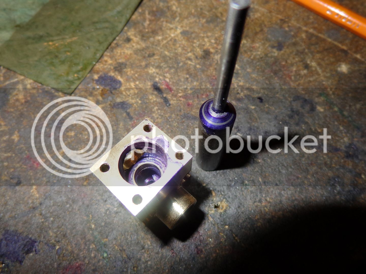
Time to pull those boot straps up and get at it Brian, I know you can do it !!!! We all pulling for you. I cant wait to see it run, then get my nerve up to try one myself... So please make it look easy as you always do...The seat grinding and valve lapping will go like clock work for you this time i promise :):)...Good luck to you
 
Sounds like you are suffering Pre-traumatic Stress Syndrome. I cope by starting late in the day so I can have a soothing libation afterwards while reflecting on the outcome. Works for me. The early part of the day is given to procrastination.

Jim
 
The floor in my little machine shop was awash with nervous sweat today, but I persevered!!! TWO set ups in the 4 jaw and a lot of breath holding yielded the intake valve body. Near as I can tell, it turned out okay. I had to stop right in the middle of the job and drive across town to a tool shop and buy a new 1/8" reamer. The part I machined today is the red colored part in the 3D model. I haven't machined the valve seat into the part yet. I will use my valve seating tool to do that by hand.
CARBINTAKEBODY001_zps664fe205.jpg

CARBINTAKEBODY003_zpsbc12fe3a.jpg

CARBURETOR-SUBASSEMBLY-X_zps5d7fae03.jpg
 
Nice work, Brian - the ol' 4 jaws aren't too bad are they ;)
 
The 4 jaw work is all finished---And I'm very proud and pleased that it all went okay!!! Everyone was right---It does get easier with practice. One of my customers called me in today with some real work, so progress may slow down a bit. I still have to make valves, and cut ring grooves on the piston for the two cast iron rings that I purchased.
INTAKEANDEXHAUSTASSEMBLY001_zpsd790b6fe.jpg

INTAKEANDEXHAUSTASSEMBLY002_zps75d6a2ec.jpg

INTAKEANDEXHAUSTASSEMBLY003_zpsdb2fcaf2.jpg
 
I came home today at noon and wanted to build something easy. There aren't very many easy things left to do, but I needed a cylinder oil cup and control needle valve so thats how I spent my afternoon. Now I'm off to the denturist to pick up new upper and lower false teeth. This has been an ongoing process for the last 3 months with impressions, more impressions, and fittings. The last time I was over there for a final fitting he gave me a hand mirror, and my God, I thought I was looking at a crocodile!!! I don't remember ever having that many teeth of my own, at least not all at the same time. My youth took a terrible toll on my natural teeth.--Between fist fights, car accidents, and too many candies, I had my first upper plate when I was 21. Watch for me---I may be a guest star on "Wild Kingdom"!!!
OILCUP001_zps4946c7f1.jpg

OILCUP002_zps03a08ae0.jpg
 
This morning I made the intake and exhaust valves and ground the seats, using 600 grit carborundum past, by hand. After a thourough cleaning, I coated the intake valve and the intake seat with layout dye, and after it had dried for half an hour, I applied a bit more 600 grit and lightly ground the intake again. I think that the annular contact ring where the contact point wore the layout dye away on both the valve and the seat is visible in this picture. Its a nice round continuous ring, with no gaps, and it passes the old "blow by mouth" test and doesn't seem to leak at all. Of course, valves have fooled me before.
INTAKEVALVEGROUND001_zps934ec8ba.jpg
 
And ditto, the exhaust valve. Perfect contact ring all around on both valve and valve seat. Its harder to see clearly on the exhaust valve, because the seat is down inside the housing about half way. I'm sure you have figured it out by now that I haven't parted the valves off from the parent stock. I do it this way so I will have something to hold onto when I grind (or lap if you prefer) the seats and valve faces. The calves are made from 1018/1020 mild cold rolled steel.
EXHAUSTVALVEGROUND001_zps5b1b59fc.jpg
 
I am in final assembly phase this morning. Just now getting to the piston rings. Book states "With ring setting squarely in cylinder bore, end gap of ring should be 0.004" as checked with feeler gauge". Ring is in there. Gap is dead nuts on both rings as checked by yours truly!!! Now if we can get the grooving tool ground properly and cut ring grooves in the piston and then install the rings without breaking them-----
RINGGAP001_zpse571ccd9.jpg
 
Ring grooves have been added to piston and rings installed. A LOT of breath holding and very light pressure and lots of lube oil!!!
RINGSINSTALLED001_zps351bb38b.jpg
 
Holdin' my breath, here, Brian. Won't be long now!

Chuck
 
Nice work, Brian. I've had the Phillip Duclos book for years and read it many times. I have learned a lot from it, although I haven't built any of his engines yet. I did sucessfully make several piston rings using his instructions. They are running now in my Upshur farm engine. Keep up the good work and thank you for documenting this build so well.
Cheepo45
 
As Ringo says "You know it don't come easy!!!" Tried to insert the piston into the cylinder---It wouldn't go. The ring grooves weren't cut deep enough in the piston. Carefully took the rings off, machined the grooves deeper--Put the rings back on. The cylinder goes in (with much carefull persuasion)---No broken rings (yet). Piston will go to within .100 of TDC and hangs up--won't go any farther. Disconnect con rod, pull piston, determine that there is a tight spot in the cylinder---right at the far (blind) end. Scratch head, time out--Sat in Lazy Boy, had stiff drink. Decided that the only way to take out tight spot is with a lap and coarse cutting compound. Made lap--Used some of the automotive valve grinding compound I bought 3 years ago at NAPA which is far, far, to course to grind tiny valves but good for tight spots in cylinders. Didn't want to lap the rest of the bore, so squeezed coarse compound in thru sparkplug hole and inserted clean lap so that only the last 1/2" of the bore got lapped. It worked, but very scary indeed. Locked lap in 3 jaw, ran lathe on lowest speed (115 RPM)--held onto cylinder and water jacket and worked it back and forth about 1/4" for slow count of 100.--Being ready the whole time to just let the damn thing go if it started to lock up.---Didn't want to spend time going round and round on lathe chuck. All turned out well. Piston is reinserted, everything goes round and round. New rings make TREMENDOUS difference in power required to turn engine over. Tomorrow I will soak everything with oil and run the motor in for an hour with electric drill to seat the rings and get rid of the drag.
 
Things are currently going together for what I can only hope is the final assembly. The two hours of "running in" in the lathe, 1 hour at 115 RPM, 1/2 hour at 210 RPM and 1/2 hour at 350 RPM has made an incredible difference in the effort required to turn the engine over. Its now back to roughly the same resistance as it had before the rings were installed. I kept everything well soaked with oil during the entire "run in" time. Here is a little tip, which has been mentioned before, but it works so slick that its worth mentioning again. If you drew or modelled your engine with any kind of CAD system, then print out any surfaces which need gaskets at 1:1 scale, glue them to your preferred gasket material (I use cereal box cardboard) and cut them out with scissors and a home made gasket punch. The two shown are for the interface between the intake and exhaust valve bodies, and the interface between the valve body and the water jacket/cylinder. Nothing will get hot enough on this engine to damage the cardboard.
GASKETS001_zpsade40e9d.jpg
 
A little "something something" to replace all of the 1/16" drill bits that I have used as pivot shafts for my counterwight arms and lock out lever. Nothing too exotic here. The steel pin goes through the pivotting bits and the brass collar goes on the other end with a dap of green Loctite.
SOMETHINGSOMETHING001_zps5bc33903.jpg
 
The engine is finished!!! It looks great. Oh, the base and a gas tank are still outstanding, but I'm not going to bother with them untill the engine runs. Will it run???????????? Thats the $64,000 question. The compression seems rather anemic, but it will stop when it comes up on compression if you flip it by hand. If (when) I get it to run, I know that the compression will increase dramatically. Thats the way all my other engines have been. I am not going to bore you with the next (trying to get it to run) part. That will be just a lot of hard slogging, tweaking, hoping, cursing---you know the routine. When its up and running, I will post some more, and hopefully, a video. Thanks ever so much for following my thread, for the constructive comments, and for helping out when I needed a bit of technical advice or a bit of encouragement.----Brian
 
Back
Top