Kozo A3 in 1.5" scale

Home Model Engine Machinist Forum

Help Support Home Model Engine Machinist Forum:

This site may earn a commission from merchant affiliate links, including eBay, Amazon, and others.
Today's project was to make handles for the throttle and Johnson bar. This shows how you can make CNC lathe parts using a CNC mill as long as you can hold the stock with a collet and not have too much hanging.

large.jpg


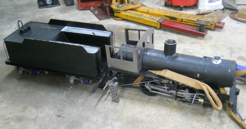
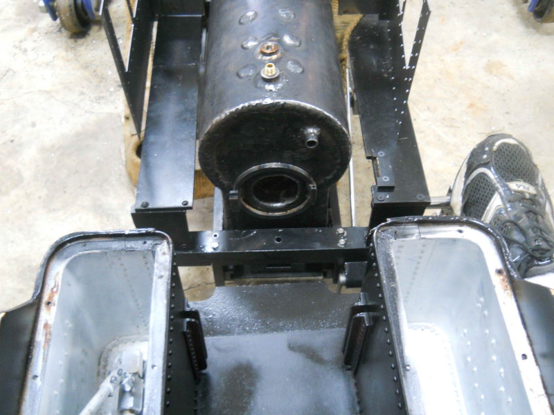
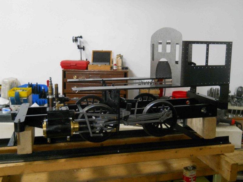
I spent most of Saturday re-assembling the chassis for a second test run on air. I made gaskets for the cylinder-tee joints, cylinder heads, steam chests, and covers, but installed only on the cylinders thus far. Since the first run on air in November I remade a number of parts (yokes, reverse brackets, running boards), and painted. Aside from the chassis, I also worked on the smokebox and its attachments (see prior thread posts), and installed the ash pan

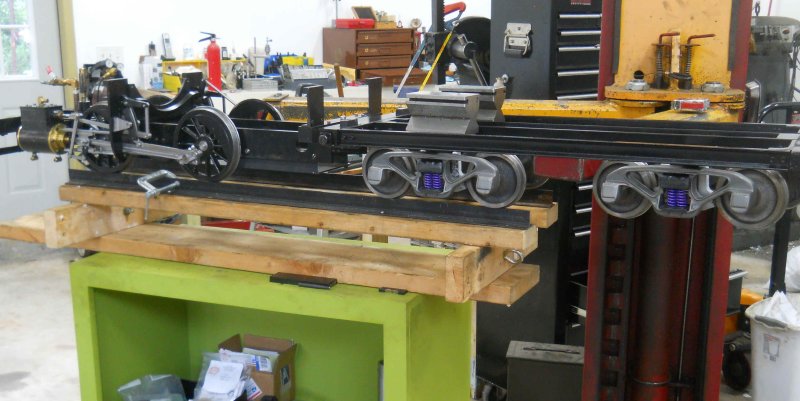
I had installed the brakes as well, but when I raised the frame on the bricks, the axle boxes bottom on the binders and jam the wheels against the shoes. So for this run I had to remove the brake mechanism.

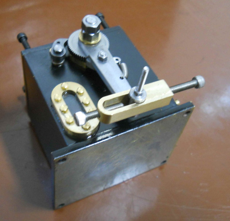
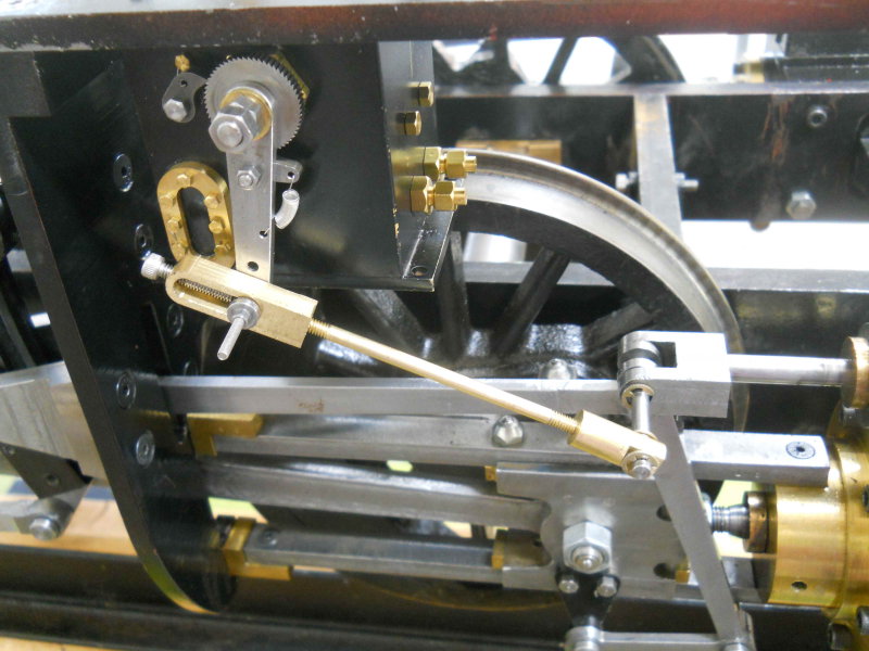
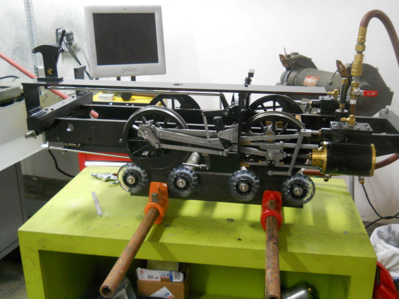
With the Johnson bar mechanism working better, the engine seems to run more free. However, there's a "dead" spot between forward and reverse that sometimes prevents a smooth transition between forward and reverse. I've been told this is fairly common, and with a little bump of the Johnson bar the spot is bypassed.

Here's the video:

[ame]http://www.youtube.com/watch?v=aGRN_yjde6E[/ame]
It would be handy to have made a locomotive treadmill; this would have allowed test with both the brakes and springs installed.

I have a week left to fix a few more bits before heading for a family vacation trip. Then it will be time to plumb the boiler.
 
Nice one kvom!!

I was thinking to myself you deserved a reply from at least one of us. Here you are posting pages and pages of good stuff and no acknowledgments from any of us lurkers. I'm sure the video will elicit a few more replies.

I'm no expert on this but to me the hissing sound when you are in neutral is the air escaping from the inlet to the exhaust without doing any work. In neutral all the ports should be shut the pressure holding down the valve block and no air escaping. So I conclude your valve timing needs a bit of work setting it up. That also may be why you've got that dead spot, the valve can't seat and the air is just escaping. I'd expect every newly assembled loco has this issue.

Its a great job you are doing there

Pete

[EDIT] its just occurred to me the reason I've experienced this problem is some of the gasket goo I was using ended up on the port face and the valve block couldn't seat properly so air escaped. Otherwise there is no way the pressure can jump the gap its either going to one end of the cylinder or the other but should never be able to go direct to the exhaust port.
 
KVOM

I have to agree with Pete. I am not into locos but have been following you with every post you submitted. It was fascinating seeing that video and it urged me to post something so that you know that I was following you also.

Vince
 
I would add my voice to those interested in your progress despite not wishing to make a loco. After reading a few of your more recent posts I went back to the beginning a read the lot. You have shared a fascinating engineering journey for which I thank you.

Jan
 
The steam chests are not sealed as yet, and I can feel a lot of air escaping under the covers. That said, there is some air coming out the exhaust as well, so I'll check the valve positions after stopping it in neutral. Thanks for the hints.
 
After 3 weeks vacation trip and a week of jet-lag afterwards, I was ready for a bit of shop time. I'm still pondering the throttle issue and got some new ideas from the Chaski forum. To see more clearly where the throttle bar would be, I decided to go ahead and finish the cab front and sides. The front is a larger piece of sheet metal than can be mounted in a vise, so it will need a fixture plate to CNC. However, the sides already have a fixture plate from when they were machined on the Bridgeport. What was needed are the holes for a decorative rivet pattern plus the holes for mounting the sides to brackets that attach the sides to the running boards and the front to the sides.

I drilled three mounting holes in each of the sides using the Bridgeport, and then matching holes in the Corian fixture plate using the CNC mill. After attaching both sides together using 6-32 screws and then to the plate, it was fairly quick to spot drill and through drill the 60+ rivet holes in both sides simultaneously.

large.jpg


Definitely faster than manual drilling.

I'll be using #7 drive screws for the fake rivets. For the front, which is over 13" wide, I'll attach a corian plate directly to the table.
 
Yesterday I took an entire afternoon and into the evening just trying to cut the cab front out of some 16ga sheet. After cutting out a Corian fixture platre I determined that I didn't have any screws that would work with the tilt tables t-slots. So I decided to try to clamp the metal, Corian, and table together in a way sufficiently rigid so as not to slip when milling. This lead to some ad-hoc clamps shown in the photo below.

The next problem was that without the vise my spindle descends only to within 3" of the top of the table. Not an issue for drilling, but I then needed to use longer endmills than I would have liked. So the window cutouts were made with a 5/8" 4-flute endmill for a roughing pass, and then with a 3/8"x3" endmill which is pretty flimsy when stuck out that far. Had to take only .02" DOC and it still buzzed in the corners.

The outer profile needed to be milled in 3 separate sections with the 5/8 EM as I couldn't clamp securely enough and clear the EM all the way around. So after each section I needed to move the clamps around before running the next. The metal still lifted off the Corian in places resulting in a lot of burrs that needed cleaning up this afternoon.

Anyway, here's the part on the mill at the end:

large.jpg


After a good long while deburring, I mounted the front and sides to the engine chassis using magnets for a poser shot:

large.jpg


Next step will be to put on the boiler again and see how it fits relative to the cab.

Since the vise was off the table on the CNC mill, I decided to take it apart and clean out a couple of years gunk and swarf. The coolant I'm using tends to clump the chips together. Slides a lot smoother after the cleanout.


Coming along nicely Kirk. You've done a wonderful job on her so far.

Ron
 
After more cogitation and some online discussions, followed by some measurement and CAD verification, I have again re-designed the throttle mechanism. By remaking the interface plate between the ball valve and the boiler, I now have the valve to the right of the centerline. This allows me to make a bell crank to attach to the valve that will lie on the boiler centerline. With the crank pointing downward, the activating reach rod will be close to the top of the boiler and on the centerline. Thus, other than substituting the ball valve for Kozo's needle valve, the rest will be quite similar.

Here's the new place and valve alongside the previous one that placed the valve on the centerline:

large.jpg


A criticism of the ball valve is that it might not be progressive (i.e., jerky starts). If that turns out to be the case, then it would be possible to replace it with a slide valve or even a v-hole valve if one could be found in this size. In either case the reach rod and the rest of the throttle mechanism would not need to be changed.
 
Still hitting some roadblocks on the throttle/dome setup, so I turned my attention elsewhere.

I've wanted to build a treadmill for the loco, since raising it off its rails to run and supporting it with bricks has been less than ideal. The components are a set of skateboard wheels plus some stock I had on hand. The 4 axles were turned from aluminum, necked down to 1/2" to pass the frames, ajnd 1/4" to fit the wheel bearing holes. The wheels are retained by e-clips. Frame is some 1/2x3" HRS. Seems to work very well during a short tryout run.

Here's the loco chassis on the treadmill. If/when I take it apart again I'll replace the clamps with a length of all-thread and some nuts.

large.jpg


Although not on the critical path to get into steam, I bought a Locoparts 12" steam whistle kit from a fellow club member over the weekend, and I decided to do the rough turning on the aluminum chamber casting. The object here was just to get it round from end to end. There was quite a bit of extra material, so no critical decisions at this point. With center drill holes on both ends, I turned the small end down to 5/8" at the tailstock, then secured that with a 5C collet and turned the entire length down to 1.45" diameter. All interupted cuts with a small DOC.

Eventually most of the length will need to be turned to a light press fit into a brass tube with an ID of 1-7/16". Before then, the small steam admission end needs a lot more work, including 2 different threads.

large.jpg
 
I like the treadmill, that is cool :)
 
Today was just dedicated to trying some things for fit. Used the engine hoist to put the loco and boiler together on the floor, and positioned the tender behind:

large.jpg


Because the plans for the 1.5 scale boiler place the steam dome further forward proportionally than for the 3/4" scale, the throttle tube into the can will be longer. I measure 5" from the rear of the dome to the front of the cab. Sitting on the rear of the tender, I would have quite a stretch to reach a throttle that was just inside the cab, so the tube will likely be extended in the cab at least 2-3" and will need to be designed not to interfere with whatever the turret turns out to be.

Here's a shot taken at eye level with me sitting on the tender:

large.jpg


It seems that the manual foot-operated brake lever will work well with my shoe resting on the tender footrest. OTOH, getting a good view through the firedoor will require scrunching over. Adding a seat or cushion will make me sit even a bit higher. Stoking looks as if it will be fine. The front of the tender and the loco's rear footplate are pretty much on the same level. Kozo doesn't use an apron on the small loco, so I'll need to make something.

The tender's provision for a drawbar is about 1/4" lower than the loco's.
 
Looking good
Don
 
I just realized how big that engine is :eek:

Very impressive!
 
Spent the last shop sessions making the drawbar and drawbar pin. To adjust the fit I used the auto lift to position the tender frame level with the loco so that the front tender truck was on my booty-fab track:

large.jpg


The attachment for the tender drawbar is not readily accessible with the tank in place, so I had to remove it termporarily.

There's about 1" of space between the tender's bumper and the loco's rear footplate. Any closer would interfere with the foot brake.
 
I will need to mount my AME lubricator on the front of the footboard rather than behind the yoke, as Kozo shows. That's because it's wider than Kozo's and thus would interfere with the reverse reach rod. So now the activating motion will be the valve rather than the eccentric strap.

The value travel at full gear is .6". OTOH the lubricator lever needs to move only about 10 degrees to advance one notch, meaning that the lowest hole on the pivot arm will move about .32". To account for this, I've made a "lost motion" strap to fit to the lever arm:

large.jpg


The 5-40 screw in the rounded end adjusts the travel in the slot. The other end will have a 1/8" diameter rod approximately 2" long connecting to the fork at the end of the valve rod. Since the lever will be a bit outboard of the valve, the connection will need to be offset from the valve approx. 1/2". I have some ideas on how to do that once I mount the lubricator to the footboard.

The holes in the lubricator's arm would be best fit by a 3-48 screw, which I don't have. For the time being I'm using a long 2-56 to fit.
 
Today's project was to finish the lubricator linkage. The photo is pretty self-explanatory:

large.jpg


Rolling along the track with the adjusting screw all the way in appears to advance the ratchet two teeth, which is what I expected with full-forward gear.

I still need to bore a hole in the footboard for the filler cap, plus get a shorter/different screw for the lever attachment.
 
Back
Top