Kozo A3 in 1.5" scale

Home Model Engine Machinist Forum

Help Support Home Model Engine Machinist Forum:

This site may earn a commission from merchant affiliate links, including eBay, Amazon, and others.
I am not sure just what the problem is .Withthe pin being just 1/16 there is not much left after making the groove .I am thinging of making shoulder bolts for some of them . This is my frist model so I have a lot to learn.Thanks Dale
 
Waiting patiently for the next update. I bought the book just to follow along. :big:
 
dalem9 said:
I am not sure just what the problem is .Withthe pin being just 1/16 there is not much left after making the groove .I am thinging of making shoulder bolts for some of them . This is my frist model so I have a lot to learn.Thanks Dale

I just realized you are building half the Kozo scale, so perhaps the e-clips don't work well that small. Given that the groove diameter on all the clips I use is .025 less than the pin diameter, that would mean only .038" of material left.

I have been sick with a cold/cough for the past few days, so not in the shop. Saturday I'm driving to KY to pick up a tender tank, to which I will be adding Tom Bee trucks. So no tender fab for me.
 
Gorgeous work. Thanks for the extra effort to post all this.
 
Saturday I was well enough to make an 800 mile round trip to pick up this tender, which was advertised on DLS. I didn't like the slant back tender that was normal with the A3, and this looked to be well made. With some Tom Bee trucks and a seat made to fit, it should work well with a small locomotive. It has a single water valve on the left side, so if I go with two injectors I'll need to add another on the right.

large.jpg


Today I decided I really, really needed to do something to make some progress on the build. So I repeated the Kozo valve timing process on the right side using the temporary expandable eccentric rod, then calculated the revised length assuming that the axles and piston rod would be on the same level. This side turned out .003 longer than the left. Then I made some temporary eccentric rods from some 1/8" steel stock using the calculated spacing for the holes. I don't want to do the real rods until I'm sure the lengths are correct. I'll need to finish making the last 4 pins for these rods, and install them with spacers of some sort, since the real rods will be .25" thick.

large.jpg


With the rods installed, I just need to adjust the pistons to be centered in the cylinders over their range, and then close up the cylinder heads and steam chest covers to give air a try. This stage always makes me "nervous", since every model I've made in the past has taken lots of fiddling to get to run.
 
Nice find kvom. :bow:

If you don't want to make another outlet in the tender you may like to think about running the injectors off a "T" piece.

Best Regards
Bob
 
My understanding of injector operation is:

1) turn on the water
2) turn on the steam
3) reduce water flow until injector overflow stops losing water

If the two injectors have different water needs or I just need to use one of them, I'd still need separate valves for each injector's supply. Given that the injectors would be mounted low down, it would seem easier to have the additional valve on the top of the tender where it's easy to get to.
 
Having made and attached the two expansion rods and adjusted the piston travel, I was unhappy to see that valve mechanism was locked up. Since it did turn with the right rod in place, I took of the left and tried to see where the problem could be. I found that when the steam chest was not screwed down tight things would move fine, but not with the chest secured. Then I noticed that the valve nut was touching the bottom of its groove. Since it appears that the valve stem and the top of the cylinder face are not precisely parallel, move the valve to the rear was pressing it against the nut and valve stem jamming the works. When I removed the valve and screwed the chest down tightly to the cylinder, the valve mechanism works smoothly.

I won't have time to mill the sides of the nut until after the weekend, but hopefully there's not too many other gotchas in wait.
 
First run on air ;D

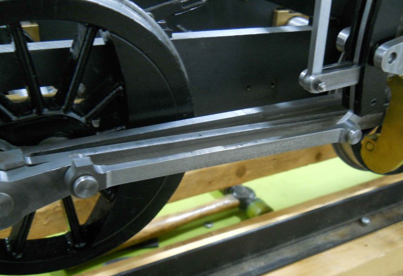
Having discovered that the valve nut was a bit off center, I milled .03 off the "long" side, reinstalled, and retimed the left sid engine. This time the eccentric rod measured out ~.01" longer, so made another temp rod and installed it. Then I moved the chassis off the surface plate onto the transport "rails", and it rolled along without hanging up anything. That was last night.

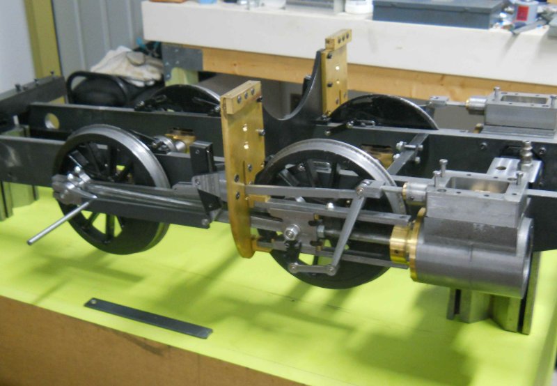
Today I installed the front cylinder covers, right running board with quadrant, and the reversing mechanism, and propped the chassis up on two bricks to clear the wheels. After attaching the air line from my mill along with an adjusting valve, it was time to test my work of the past year.

Initially I set the valves to neutral position and turned on the air at 20 psi. Most of the air leakage is between the cylinder and steam chest (there are no gaskets in place as yet). After tightening the steam chest covers a bit I moved the quadrant to full forward and increased the pressure to 65 psi. The engine didn't staer by itself, so I tried moving the drivers by hand, and it sprang to life. woohoo1

The reverse reach rod is not adjusted properly, so putting the quadrant into full reverse doesn't shift the radius rod fully up, but it does run slowly in that position once I turn the drivers backwards.

I am assuming that the engine will "run in" after a while, allowing it to self-start without my help.

So now it was time for the obligatory video:

http://www.youtube.com/watch?v=VlSsMNs8cE4&feature=youtu.be
 
Today was redo day. The running boards I'd made earlier were HRS from my local redneck steelyard, and didn't finish very well. I therefore ordered two pieces of CRS .25x2.5x36, which have been waiting my attention for a while. These will look a lot better as I didn't need to try to facemill them (definitely a problem for pieces this long, 26.75"). The extra 9" sawed off the ends of each will be used for making the eccentric rods.

I didn't drill holes for anything other than mounting to the chassis plus the quadrant. I won't be attaching the battery "tank", and the holes for attaching the cab need to be re-calculated later. I' also undecided about whether to make the manual cylinder cock linkages. I'll drill the hole(s) for mounting the lubricator when I get it.
 
Sweet! Congratulations! I loved seeing it run slower in reverse! You can see all the rods and links doing their job! Well done!
 
A big day, well done. Its tight because its been made so well made. The Rob Roy I finished was that tight to start with one of the club members recommended plenty of oil and run it on air for 6 hours or so. It soon freed up and now runs like a sewing machine.

I used Finish Line bike lubricant, because I had some, and it proved to be very effective and once you get the loco running the lube stays where you want it.

WET_Lube_Family_th.jpg


The spray can is really useful as it has a long nozzle that you can safely get lube into places you want it, even while the engine is running.

Get it from the bike store

Pete
 
Congrats kvom! Long road to there isn't it.

You'll get there...just keep going. I'm looking forward to the first run on steam....nothing even comes close.

:bow:

Dave
 
Onya kvom, :bow: :bow:

Best Regards
Bob

 
This week I drew up the cab sides and front in CAD. The sides I scaled up 2x, and the front I scaled 2x on height and set width equal to the outside edges of the running boards (13.25").

I am wondering what gauge of sheet metal to use. For the 3/4 scale Kozo specifies 1/16 thick, but 1/8 steel seems stiffer than needed. I'm thinking 13ga might be about right. What say you?
 
The "stiffness" of the material goes up as the cube of the change in thickness (as I recall) so your 13ga material is going to be about 3.75 times stiffer than the 16 ga specified on the plans for the smaller engine. I'm not familiar with the details of the cab design, but if it has any bends they will be much more difficult with the thicker material especially if they're close to an edge. If it's all made up from flat plates, this won't be an issue except for the cutting time. If you're going to cnc it even this will be a small issue. How big is the cab "box"? I'm thinking that 16ga may be just fine unless it's something that you stand or sit on and even then it may be just fine. The bigger issue may be how it's fastened to the loco. These are likely to be the areas of highest loads and, therefore, the areas most likely to distort if the cab is inappropriately loaded. Regardless of thickness, if you're going to CNC the parts there is an opportunity to cut some bend lines part way through the material and then you could probably bend the part up by hand right over the edge of your bench. This would be a really nice way to construct the "box" and would take advantage of the equipment you have to make the job easier and the results better.
Regards,
ET
 
I made the eccentric rods over the past few days, replacing the temporary ones. All of my small ball oilers are two large for these, so I still need to make some brass oil cups (some holes might be enough).

large.jpg
 
Back
Top