Kozo A3 in 1.5" scale

Home Model Engine Machinist Forum

Help Support Home Model Engine Machinist Forum:

This site may earn a commission from merchant affiliate links, including eBay, Amazon, and others.
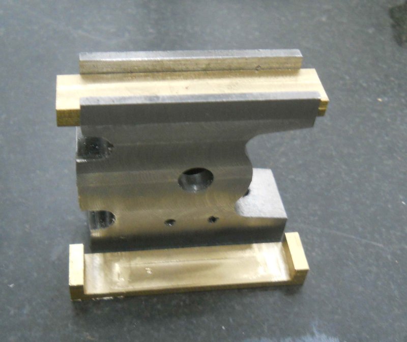
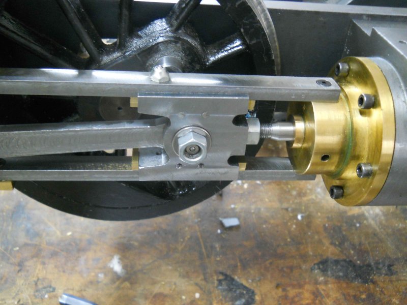
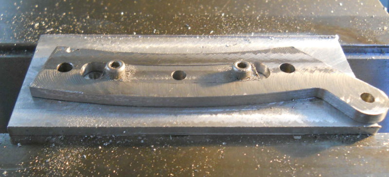
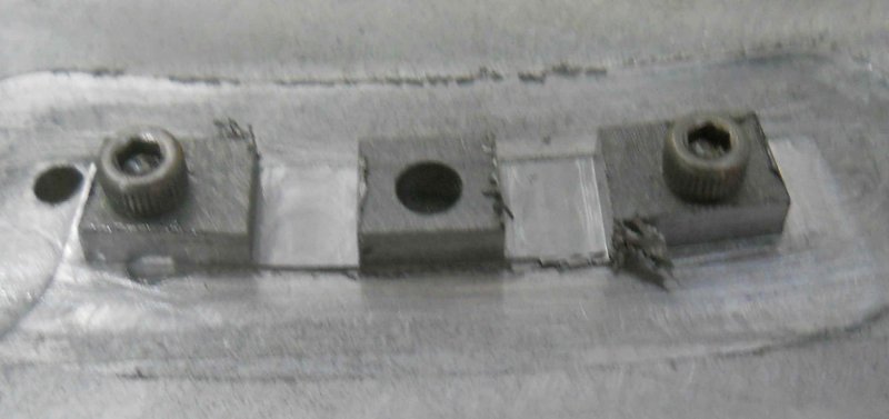
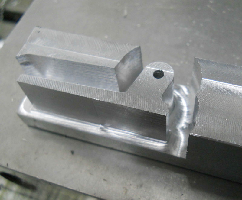
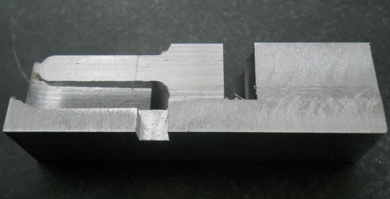
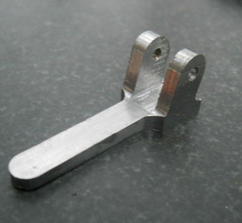
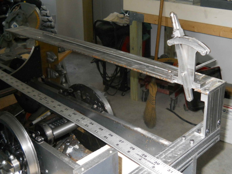
Got the crossheads machined, slippers installed, and fitted to the guide bars. These took more time and trial and error than I had anticipated. One issue that cropped up was my 5-40 flat head allen screws. With the slippers only .086" thick, the heads were still proud of the slipper surface even with countersinking. My solution is shown here:

large.jpg


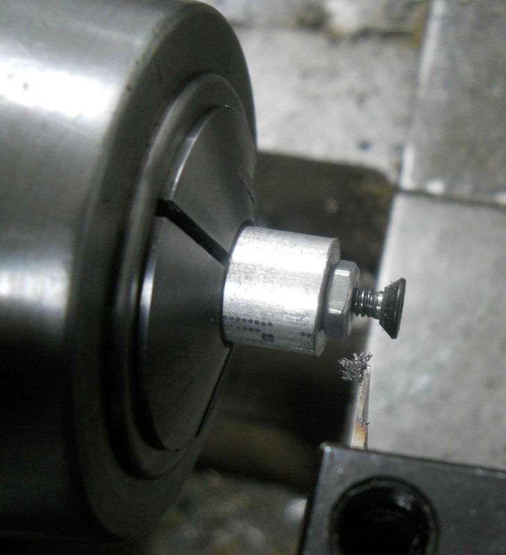
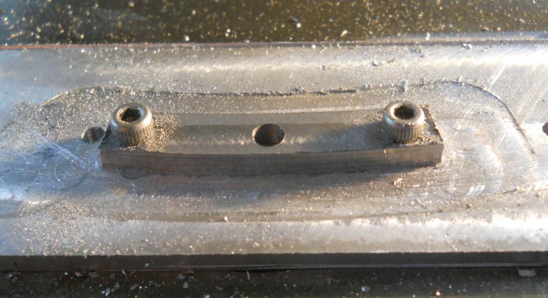
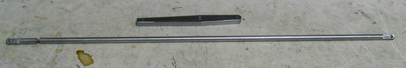
I drilled and tapped a short piece of 1/2" aluminum rod and used it as a "fixture" to hold a screw and lock nut. Then I used a grooving tool to take down the lower part of the head taper. Hopefully this is a temporary necessity until I can get some brass screws, but I am thinking that using loctite as well as the screws may be a good plan.
 
Thanks to John (FLSTEAM) for the idea, I now have slippers that don't need screws. Thanks John.

large.jpg


large.jpg


The crosshead slide pretty smoothly when I turn the rear wheels to drive the rods.

Now I can get on with the die blocks (link blocks per Kozo). I got the material and a fixture ready today, so CNC tomorrow.
 
Now that is one neat idea!!

To bad mine are already silver soldered. :-[ :-[ :-[ :-[

Ron
 
SS slippers are not a terrible idea. You can solder them in and then machine to fit.

Today I took a shot at making the link (or die) blocks, which are a vital part of the valve system. They need to be a good sliding fit to the curved expansion link grooves. Since the radius of the larger curve is over 7", it's pretty hard to even see the curvature once the block is made (it's ~ 1/3" wide). I went through two pieces of material before I got one good part, and that's with about 5 hours of shop time.

I start with a 2.5x.75" piece of 1/4" steel and mill the faces to .130" thick, then drill three holes. Two ar for mounting the blank to an aluminum fixture plate with 5-40 screws, and the other is a 5/32 hole that will attach the link block to the radius rod via a pin. The blank is then machined down to this on the CNC mill:

large.jpg


I then used the expansion link to check for fit. I needed to modify the program a couple of times to get the fit I wanted. The last pass took .001" off the radii.

large.jpg


Then the CNC program cuts the sides, leaving .010" at the bottom. The block gets detached and has the sides filed.

large.jpg


Finally:

large.jpg


I still need to file the ends of the expansion link flat, as well as making the other block and the pins, before assembling everything again.
 
Congrats, thats a lot of work to do it right. I think I may have been tempted to just take a file to that curve in the first place.
 
Not a lot to show since the last post (too much tennis and football to watch). Parts I did complete are:

1) The reverse shaft bearings (pg. 114, fig. 18-16). I made the shape a bit different from Kozo's to make them easier to machine. I also drilled/reamed the holes 1/4" rather than Kozo's 5/32" as I have a good quantity of that size drill rod. I am now thinking that a bronze bushing here might be a good idea to avoid steel on steel movements.

large.jpg


I also made the radius rod hangers (fig. 18-17); these are called lifting links in another model I've attempted. In any case, they are pinned to the end of the radius rod and are part of the reversing linkage.

large.jpg
 
Kvom---You are a very dedicated modeller, and you do beautifull work. I admire the things that you build and post here.----Brian
 
Thanks for looking in, Brian.

With not a lot of shop time available this afternoon I decided to do a simple part. However, it seems that the stock prep, fixturing, and setup take just as long for the simple parts as the more complex ones. In any case, here's the quadrant (p. 112, fig 18-5). It would been just as efficient to machine the stand and quadrant from a single piece of stock it seems. Anyway, that's for another time.

large.jpg
 
Your rapidly expanding a collection of machined steel there. Are you going to paint it all or give it some chemical blackening treatment?
 
I'm not sure what parts to paint or otherwise coat, or else leave bare. Some parts might get nickle-plated.

Today I worked on the quadrant stand, which has two pieces soldered together. Here's the main vertical part along with the previously completed quadrant:

large.jpg


The three pieces screwed together as a test fit; the stand is a bit over 3" tall:

large.jpg


With the stand and its base silver soldered together. I used a bit too much solder wire, so will have to file off the excess:

large.jpg

 
This afternoon I machined the base form of the reverse lever, and then make the 2-piece reach rod that will connect the lever to the reversing arms. Since I had no 5/16 drill rod as per plan, I made the rod from 1/4 drill rod. The adjustment end is threaded 6-32.

large.jpg
 
A short Sunday shop session today was devoted to making the "latch lever", which attaches to the reverse lever and allows for latching the reverse lever to the quadrant. I had a piece of 7/8 square 12L14 bar rescued some time ago from the school scrap bin. The first operations were to CNC mill the side profile and drill the mounting hole for a 6-32 screw:

large.jpg


Then the bottom profile, also via CNC:

large.jpg


Finally manual milling operations to whittle the lever away from the attached stock:

large.jpg


The part is a bit more than 1.5" long. It still needs a bit of polishing.
 
I made a bit of progress on the reverse lever and running board, but first had to remake the support plate and get it square, which took a bit of time.

large.jpg


I'm going to have to remake the running board as I discovered that I had drilled the mounting holes on the yoke 1/16" too close together. While I could likely fudge a fix to that, I don't like the material I used. I started with some nominal 1/4" CRS, but by the time I had milled off the slag on both sides the thickness was down to .200". I had to clamp it on the mill table and use a 1.25 facemill, but the need to move it couple of times because of clamps and its length (27") made the machined finish less than ideal. Maybe a thick coat of paint will cover the tool marks. In addition, there's a perceptible arc, which I might be able to straighten with a press.

Is there some standard stock that I can order (width is 2.5") that has a good enough surface to paint directly without milling?
 
Most anything cold rolled will, but if your machining one face of it the stresses will warp it.
 
If you were machining "slag" off the surface, you more than likely was using "hot rolled" steel. True cold roll or 1018 steel is clean except for the grease and oil they put on it to keep it from rusting. It comes in many forms and shapes. Check with Speedy Metals. He's their link: http://www.speedymetals.com/
Larry
 
Not a lot of visible progress as we had a 3-day meet at the club, plus I've been doing a few small parts not photo-worthy. The past couple of days have been for painting some parts (low gloss machinery enamel). I did make the reverse shaft (pg. 114, fig. 18-14). In the 3/4 scale version it's made with 5/32" round rod bent manually, but using 5/16 didn't look possible, and even with torch heating getting the ends to stay straight and aligned looked very iffy. My solution was to mill the curved section from some steel plate, and then press 1/4" drill rod into each end. Not that pretty but it appears to work:

large.jpg


As the assembled parts are now reaching a weight that I don't want to be lifting by myself, I've wanted to get some sort of rolling cart with rails to hold the loco in the shop, along with a railed sheet for transport in my truck bed. I found this computer desk at a local thrift shop (for all of $5). It's made of pressboard of some type, but the boards are thick and the desk and wheels seems sturdy enough. I also found some leftover T-beam steel in the garage which will serve for rails, and I bought a piece of 1x10" pine 4' long for the truck bed. So for a total of $12 in material cost I don't think I can go far wrong.

large.jpg


My plan is to make the truck bed carrier first in order to determine height of the rails off the ground, and then adjust the rails on the cart to match.
 
The first job today was to afix "rails" to my transport plank. The rails are 1/4" square steel bars fastened with wood screws (holes were countersunk). After moving the chassis to the board, I discovered that the drivers and side rods still rub on the yokes as the spring rigging is not installed. Seems to me that they shouldn't rub anyway, so I'll plan on milling some additional relief on the yokes.

large.jpg


I'll add some eye bolts for hold-downs.

Then I spent some time cogitating on the cart, how to load from the cart to the truck bed, etc. etc. The first problem was that measurement showed that the top of the cart is 6.75" lower than the truck tailgate. Rather than try to shim a railbed that high, I figured that using the auto lift to raise the engine to the truck bed would be the most sensible idea. Some experimenting with pieces of lumber left over from the shop build finally yielded a workable idea as shown below. Please remember that my engineering degree was from 1971 and is a bit rusty.

large.jpg


So 4 pieces of lumber. The bottom gives a base, and attaching it to the two "ties" prevents them from racking. The ties give clearance for the arms of the lift to go under the rails, which are supported by 2 2x4s. The rails themselves are just lengths of steel with a T cross-section. Everything will be connected with screws.

After some more thought, it occured to me that I don't need the roll cart. I can leave the loco and support mounted on the lift to work on it, and then when I need to use the lift or the parking area I can lower it onto two wheel dollies like the one shown in the photo on the right. I can then wheel the loco around with the dollies.
 
I got the support "cart" screwed together this afternoon and mounted the chassis on the "rails". With the base plank on the wheel dollies it's easy to move about the shop floor:

large.jpg


I can wheel the assembly under the lift arms and then raise it to a nice working height.

large.jpg


Now back to working on the parts.
 
Great lift. I hope there is something stopping it from rolling off the end it would be a shame, no disaster if it fell off. Just wondering what it will weigh when done?
Brock
 
Because the wheels rub without the springs rigged, the loco as shown won't roll by itself. I did put some clamps on the rail ends after the photo. Loco with boiler should end up at about 150 lbs.
 

Latest posts

Back
Top