Kozo A3 in 1.5" scale

Home Model Engine Machinist Forum

Help Support Home Model Engine Machinist Forum:

This site may earn a commission from merchant affiliate links, including eBay, Amazon, and others.
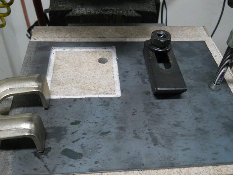
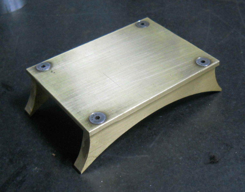
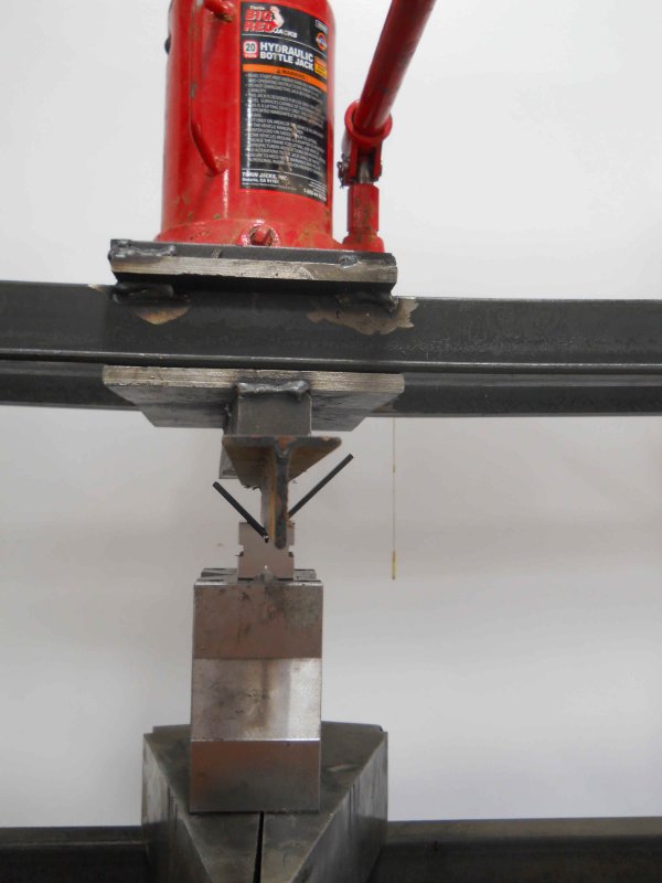
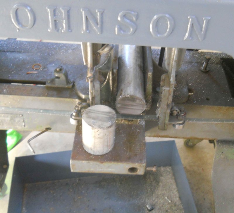
After holidays and some family obligations (and some lazy periods), I got back in the shop today. Many of the parts I need to machine next depend on the diameter of the boiler and smokebox that I'm having built, so today I decided to work on the front footplate. I had previously cut the plate itself from some angle iron, so most of the work was making the 4 brackets. First needed to bend them 90 degrees. As it's 1/8" HRS, I used the shop press set up like this:

large.jpg


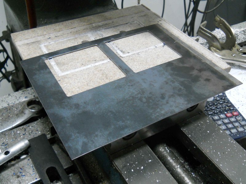
Then I just needed to mill each of the 4 to the same size and drill holes for mounting. Here's the end result:

large.jpg


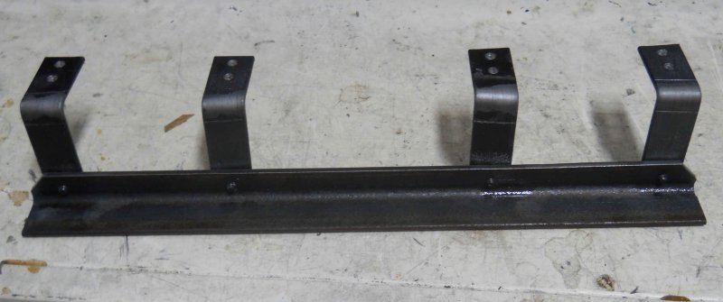
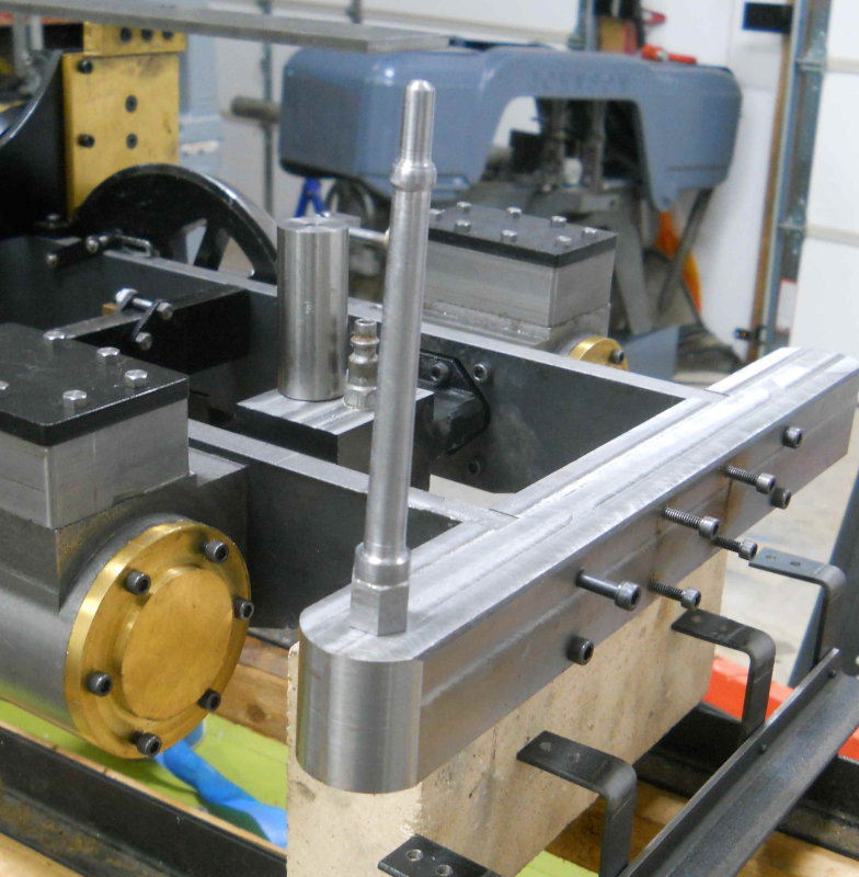
Per Kozo's instructions, the assembly will be used as a drill jig to attach it to the underside of the pilot beam.

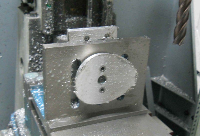
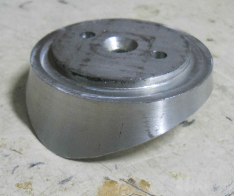
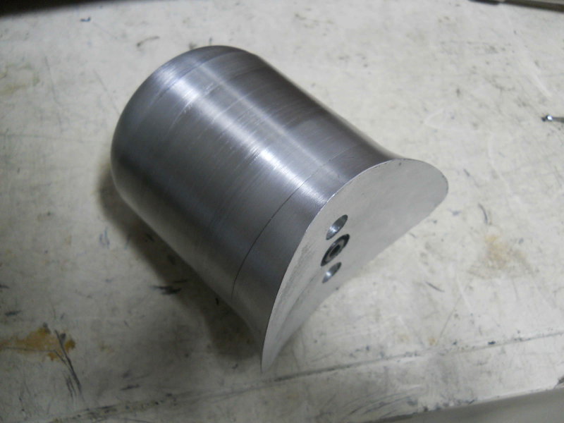
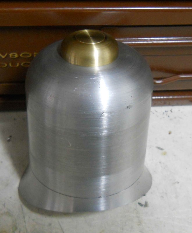
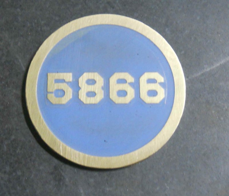
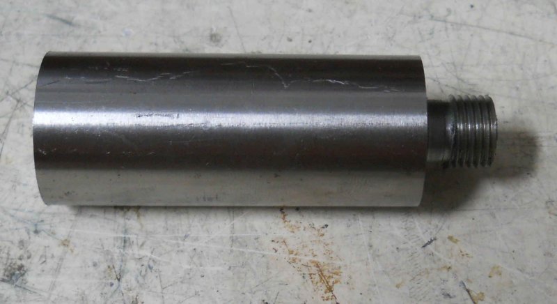
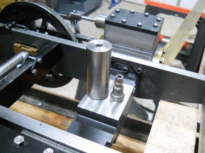
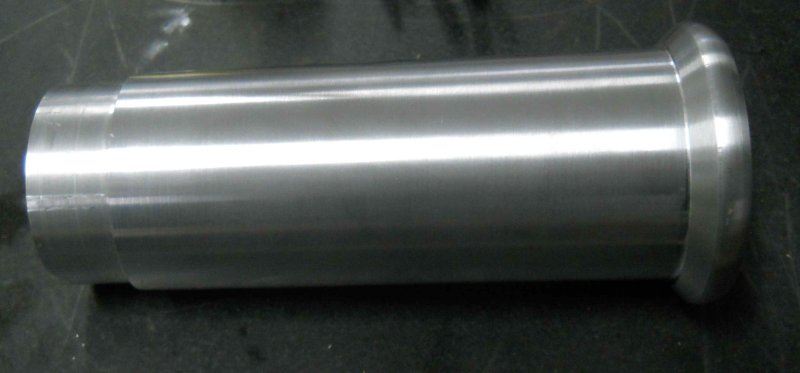
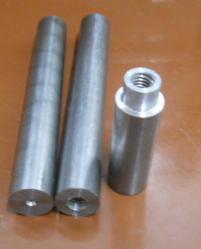
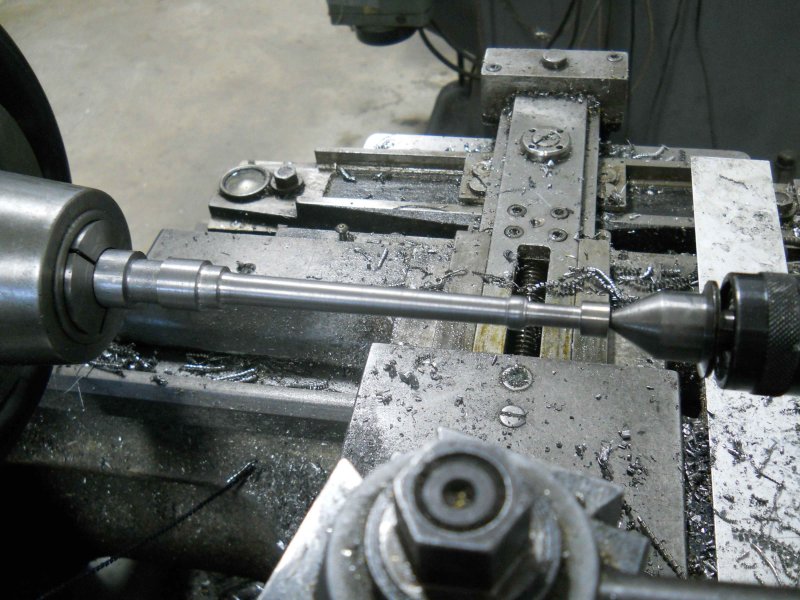
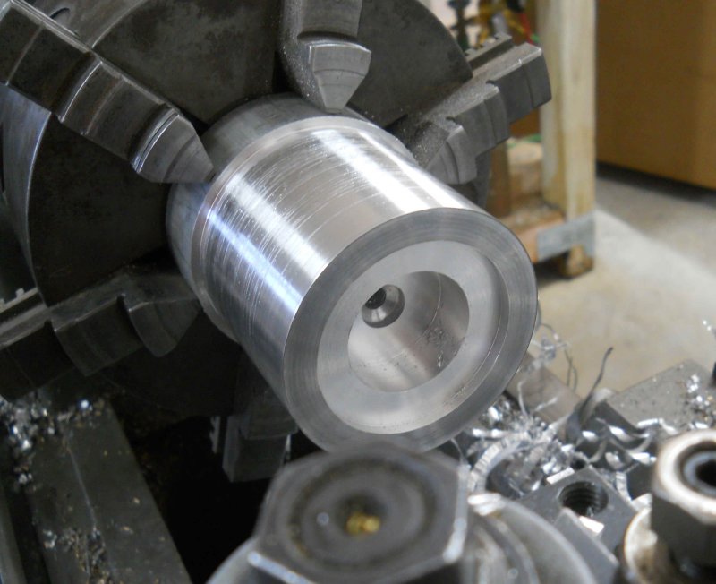
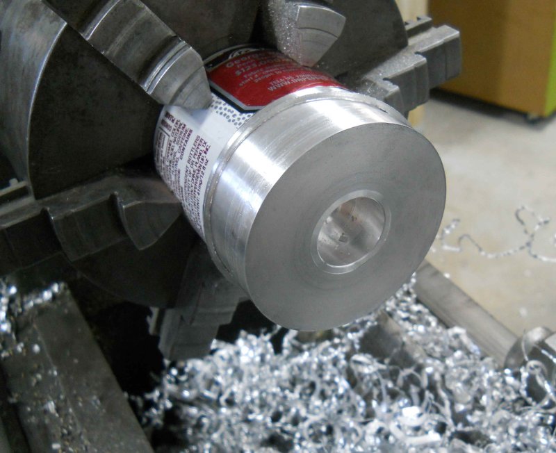
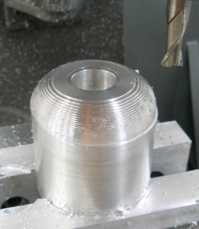
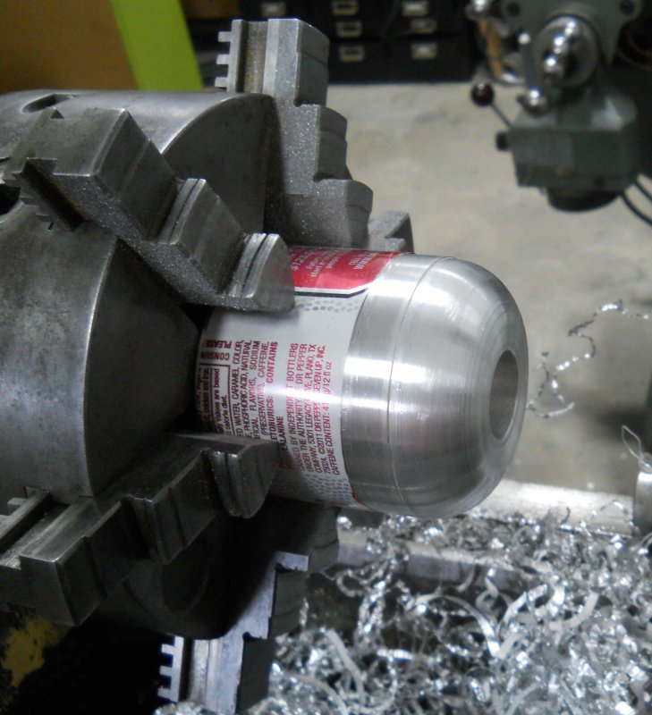
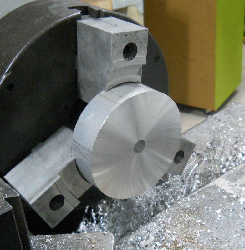
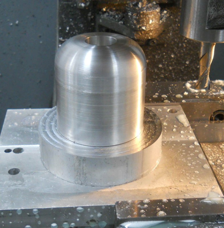
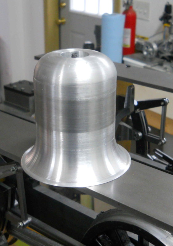
I went to Metal Supermarkets yesterday to get some 16ga sheet steel to make the sides and front of the cab, and while there found a pieces of 4" round aluminum in the cutoff bin. My plan is to mill the sand dome saddle from it, and then the dome itself from 3" diameter round that I already have. If that works out OK I'm going to do the stack saddle the same way, although I'll need a larger diameter piece of stock for that saddle.
 
Last two days in the shop were used to fabricate the body of the sand box (dome). Scales 2x the dome would have a diameter of 3-1/8", but as I have a stick of 3' aluminum it was made at 89% of scaled.

First step was cutting a 3.5" long slice at the bandsaw.

large.jpg


Next, mount on the lathe, trim the sides, then face, drill and bore the bottom.

large.jpg


The dome is fastened to its base and the boiler via a long screw that connects to a filler plug on the boiler. On the 3/4" version, the boiler is filled via this fitting, so at steam up the dome is removed to unscrew the plug. On my version, a blowdown valve will have a hose fitting. However the boiler will still have either the same plug or a bushing for attaching the dome. The deeper bore in the bottom is necessary to clear the plus or bushing, and the shallower bore is for mating with the base.

Next I reversed the piece in the lathe to face the top and bore for a removeable cab to be made later.

large.jpg


The work was then moved to the CNC mill where it was secured by pockets milled into soft jaws. The spindle was then centered using the top pocket.

large.jpg


The CNC program then mills the top contour radius using .03" steps. The CamBam program I use allows specifying sloped, conves, and concave side profiles in this manner. I'll use a similar program to mill the convex profile for the base, and later for the steam dome and stack base. A CNC lathe would make this easier, of course.

large.jpg


Then, back to the lathe to smooth out the steps with a file and sandpaper. Final sanding and polish will be done with the dome and base screwed together.

large.jpg


large.jpg
 
Continuing on today with the base of the sand dome, I started with a 4x1.2" aluminum drop found at Metal Supermarkets. The saw cuts were very straight, so only a .02" facing cut needed, followed by drilling 1/4 and counterboring.

large.jpg


Mounted on a fixture block on the CNC mill, where the first operation was a boss to fit the dome. The reason the plate is off center in the vise is so that the mounting screw could be accessed from below. I had set X0Y0 there by drilling a 1/4" hole through the plate, so no need to use a center finder. All the cuts on this part are very light.

large.jpg


Check for fit with the dome:

large.jpg


Now mill a concave profile using the same .03 depth increments I used for the dome top.

large.jpg


Then screwed the two together and chucked in the lathe to file and sand the base. Here's the result.

large.jpg


The next operation will be to mill the bottom of the base with a 3-5/16" radius to match the OD of the boiler. That's for another day.

 
Um, I hate being the bearer of possible booboo but if I'm reading the plans right shouldn't the radius be cut in the base before the rim is profiled? Cutting the radius now will remove a big chunk of the flange. :hDe:

Really enjoying the build by the way. :bow:

Cheers

Jeff
 
Looks like you are correct :eek: 
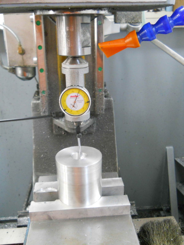
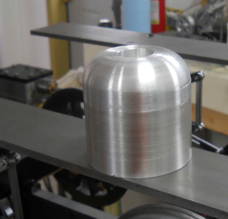
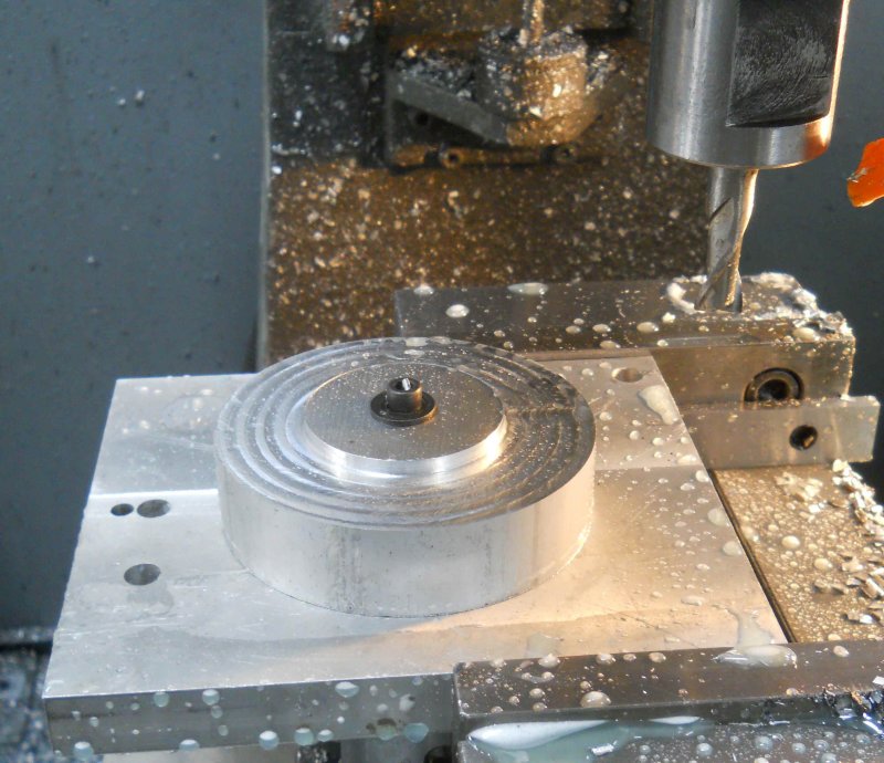
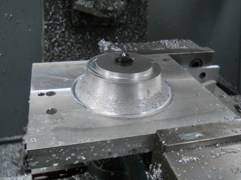
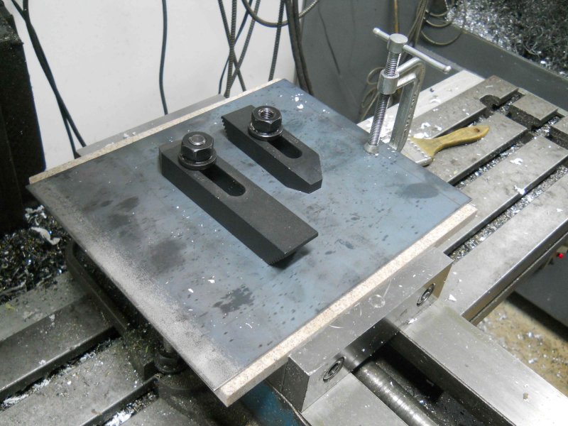
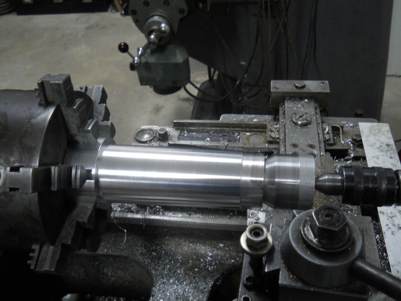
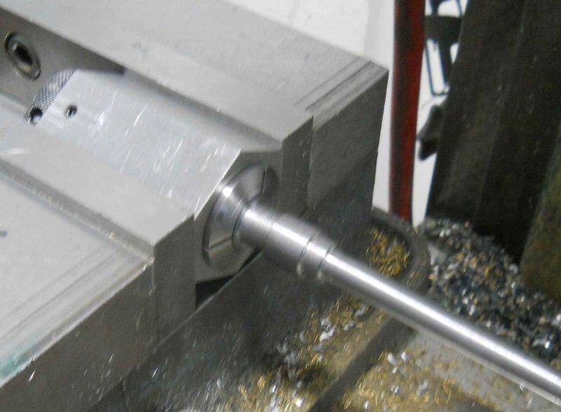
Seems that I needed to first do the radius for the front-to-back, then the radius for the boiler.

I guess I'll forge ahead as it is and see how it comes out. I don't have another piece to start over.

It might look OK ;D
 
I continued on with the sand dome base today, not without some issues. Here's my final setup after machining the radius for the boiler shell.

large.jpg


The first try I did with just the center hole and one 1/4" screw. Even as tight as I could get it the piece spun once the mill started at the top. So I drilled two more holes to bold the base securely to the angle plate. Since the raw diameter is 4" I needed to use my longest endmill to reach, and that with only .75" hold in the collet. Given 4-1/8" of stickout. G-wizard computed .05" DOC and .125" radial engagement, meaning 6 passes at each level to avoid deflection of the tool. Ran it at 54 ipm and the milling ran in about 40 minutes.

Removed from the plate and some cleanup filing:

large.jpg


And screwed back onto the dome:

large.jpg


Those edges were sharp, so I cleaned up with a deburring knife.
 
After spending the afternoon at the railroad and having a couple of hours afterwards, I made a start on the cab my machining one of the sides. Stock is 16ga HRS sheet, with fin ished part 9.5x7.25". I had a free piece of Corian that I wanted to test as a fixture plate, so I clamped the steel to the Corian and clamped in the mill vise. Note that the jaws are reversed in order to support a piece this large. The 1/2" holes for the clamp bolts were drilled where the windows will be:

large.jpg


After milling the perimeter with a 1/2" HSS endmill, I used a 7/32 2-flute to cut the windows:

large.jpg


I had to keep moving the clamps around to clear the window area, but finally got both cut.

large.jpg


The other side will be done the same way, but the front has curves and will be done on the CNC mill.
 
After a period of not working in the shop, I managed to make a little progress. The first item is a cap for the sand dome that hides the cavity where the hold-down screw lives. Made from some 1-1/4" brass round.

large.jpg


Having obtained some 1/16" endmills from my friend Ed, I made a first try at the front number plate. I had learned that PRR used their own fonts for these numbers, and that the round plates used a blue background with yellow letters. Another A3 builder (keninrc) supplied me with the PRR font, so it was time to to the CAD/CAM for engraving the plate.

I skipped photography on the steps, but here's the first attempt, from 1/8" sheet stock:

large.jpg


I had a CAM error, so this one will be scrapped after being the test for the paint background. The machining went as follows. First, I used a 1/8" 2-flute square endmill to rough out the cavity. I wasn't sure how deep I wanted to go, so did .003 at a time and finally went .009 deep. Then I used a 1/16" 2-flute square to further mill the number (the 8 is finished at this step.) Then the 5 and 6s were to get finished via a 1/16" ball mill at .005" deep. However, I didn't give this a new tool number, so no tool change and the square endmill kept running. Meh!

I gave it a brief surface polish with some 600-grit paper, and have spray-painted it with rustoleum. Once the paint dries I'll sand off the paint from the letters and border. If all goes well, I'll try to find some blue paint of about the right color and make another.
 
Today I started to draw the front and back plates of the smokebox saddle, since I obtained a suitable piece of 1/4' steel plate to make them. Then I looked more closely at the drawings, and realized that my conception of the saddle was wrong. On many models the saddle is part of the cylinder casting(s), and it serves as the support for the smokebox. However, on this model the saddle is supported by the smokebox. The support for the smokebox is provided by the vertical part of the tee containing the steam supply and exhaust channels.

Since my tee was not milled with the vertical arm, I will need to make a support piece through which the exhaust will flow. This piece will need to screw into the tee's exhaust port (threaded 1/2-20) and be the correct length to just reach the bottom of the smokebox. The top end of this support will be threaded to accept the exhaust nozzle. The nozzle will thus act as a screw to fasten the smokebox, exhaust extension, and tee securely together. The saddle itself just hangs from 4 screws that attach it to the smokebox.

Since I won't know precisely the distance between the tee and smokebox, I can't make the saddle front and back plates. I also can't finish the exhaust extension, although I can partially complete it. OTOH, I can make the exhaust nozzle and rough out the petticoat.
 
stevehuckss396 said:
The plate looks cool. It seems the cutting ended before finishing. Something bad happen?

I started by machining the main pocket with a 1/8" endmill, leaving the numbers as islands. I increased the depth by .003' per pass until .009, at which point I decided it seemed deep enough. The next op was using a 1/16 flat endmill to profile the numbers. This was at .003 (still experimenting). This finished the '8', but wasn't small enough to get into the upper parts of the 5 and 6. So the plan was to use a 1/16 ball endmill at .005.

My booboo was not changing the tool# for the last tool, so Cambam didn't generate a toolchange code, and the flat endmill then went into the numbers thinning their widths. For a remake, all three tools will have a target depth of .005.

The outer diameter was cut using 3 tabs, which were easily filed away afterwards.
 
Being a rainy day gave some shop time. The first job was to remake the number plate. The blue color was the closest rattle can I could find to a picture I'd seen of a PRR round plate.

large.jpg


I made a start on the smokebox support member. 1" steel rod drilled 1/4" through, then threaded 1/2-20 on one end.

large.jpg


With the support show in place. The final length will depend on the smokebox bottom when set level.

large.jpg
 
I will not be using the collar to attach the stack to the smokebox, but rather will have a separate petticoat. After some reading on Chaski, I watched Dave Sciavi's (trainman4602) two videos on smokebox design. The 3 "principles" exposed are:

1) blast nozzle diameter is 1/7 of cylinder bore diameter; in this case it's .25"
2) Position of the nozzle wrt the stack top is that both lie on a 7-1 cone
3) Position of the petticoat wrt nozzle is that both lie on a 3-1 one.

Given that my boiler OD is 7.5" and that the stack is scaled from Kozo's drawing, I first drew the smokebox with the stack together (using Draftsight as CAD). Next I drew the 7-1 cone from the top off the stack, and determined the position in the smokebox where the cone's width is .25". This fixes the top of the nozzle.

Then I drew the 3-1 cone from the edges of the nozzle. Assuming that the petticoat would be made from a steel tube with a 1" ID and 1.5" OD, I determined where the cone was 1" wide. With the entry flared .25" the position of the petticoat is fixed.

The result is the attached drawing. The dimensions differ quite a bit from Kozo's scaled dimensions.


smokebox and stack.jpg
 
Kvom,

Nice looking engine :bow:... been following along for some time ... great work. :)
Hope to get back to my 3/4 sometime soon.


Pat
 
Not wanting to let the entire Christmas weekend pass by without some shop time, I decided to have a go at the headlight bracket. I took a little different tack than Kozo:

large.jpg


Feet are CNCed to match the smokebox OD from 1/4" sheet, with the top from 1/8".

The screw heads will probably be hidden when installed, unless I decide to paint the whole thing black. Per the plans, the feet would be attached to the smokebox by 4 screws angled in. I'm thinking instead to just use two screws from the centers of the feet, which will be easier to locate accurately.

 
I worked on the smokestack the past two days, with around 14 hours shop time invested in it. I started with a 6.8" long piece of 3" round 6061 and ended up with this:

large.jpg


plus a huge pile of swarf stringers all over the shop floor.

The bore is tapered 4 degrees included angle, and to get the stock secure enough in the lathe (I haven't a steady rest), I bored soft jaws. After drilling through with my largest drill bit (15/16), I then bored straight to the minimum size of 1.375. Unfortunately my longest boring bar only reaches 4.5", so I was obliged to bore the taper from both ends. Since this means swinging the taper attachment to the opposite side (hard to get an exact angle match), and since there was a bit of runout at the small end, I ended up with a small ridge on the inside, but hopefully not enough to matter.

I didn't take pics during the turning, but here's a pic of my setup for turning the outside taper (2 degrees included). This was a lot easier.

large.jpg


The right end is supported with my home-brew bull center.
 
Today's task was to start the two "handholds" that attach to the ends of the front pilot beam. Those building the slantback tender would male 4 of these as there would two on the tender's foot plate.

Starting with 3 pieces of .75" round 12L14, I faced and tapped each 3/8-16 as shown here:

large.jpg


The piece on the right is a fixture to be held in a 5C collet. I screwed in a bolt and cut off the head:

large.jpg


Then for turning the setup is like this, with the work screwed onto the fixture.

large.jpg


After turning, the collet and work are placed in a hex collet block to mill the bottom section to fit a 9/16' wrench.

large.jpg


One completed item shown where it will be attached to the pilot beam.

large.jpg


The second one will have to wait for the next shop session.


Looking good Kirk. I bet she's getting a little hefty by now. ;D ;D

Ron
 
Just back tonight from Cabin Fever with thealmost completed boiler. I need to supply a drawing for the steam dome, which Wayne Godschall will ship along with the safeties. I drove up Thursday, attended the auction on Friday, looked at models on Saturday and bought stuff, then headed home this morning. I'll post pics once I get the car unloaded.

Stuff bought for the engine at the show:

1) From Locoparts: blowdown valves, boiler check valves, stancions, and lubricator check valves. I was going to get a water glass assembly, but still need to figure where to drill and tap the backhead for the glass, and then will know the size glass I need.

2) From Rail Supply: a nice casting set for a bell and mount.

3) From PMR: whistle valve, some 5/16 brass pipe, and a tree of elbows.

The loco will diverge from the Kozo design in a few ways, based on discussions this week and the boiler design:

1) Rather than a single lubricator feed through the bottom of the tee, I'll be using a dual-port lubricator with steam oil fed in through the steam chest cover as per the prototype.

2) The throttle will be located in the smokebox rather than the steam dome, with the control rod through a longitudinal stay.

3) I won't be using a snifter valve, being advised that for this size loco they are normally not needed.
 

Latest posts

Back
Top