Kozo A3 in 1.5" scale

Home Model Engine Machinist Forum

Help Support Home Model Engine Machinist Forum:

This site may earn a commission from merchant affiliate links, including eBay, Amazon, and others.
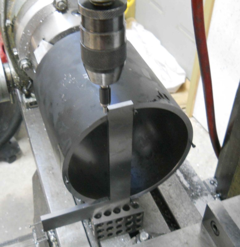
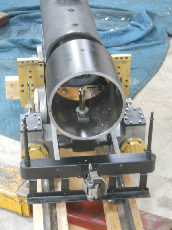
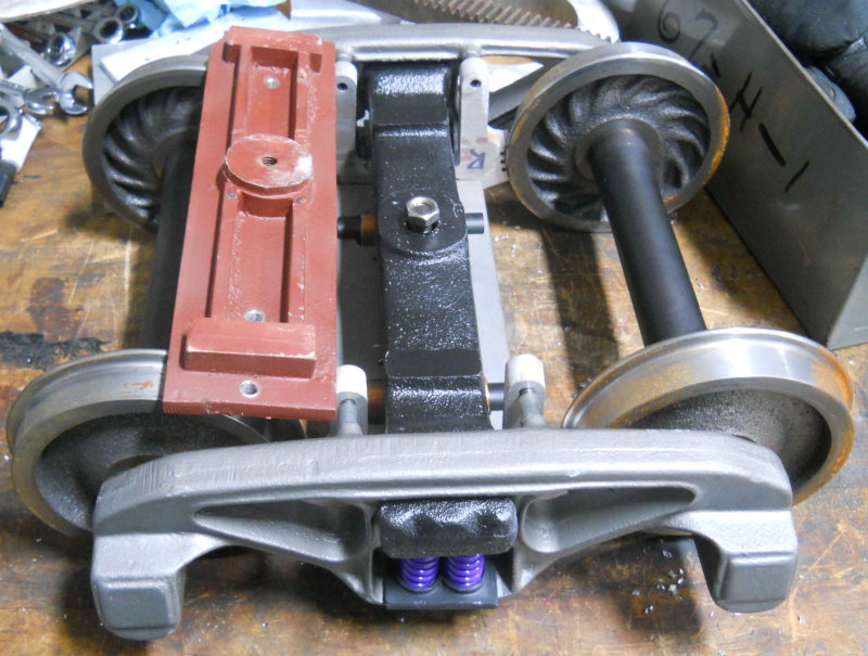
Today I mounted the boiler inside the frame for a test fit.

large.jpg


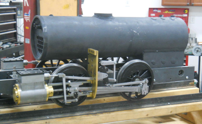
I put some metal bars under the barrel and across the frame to get the boiler barrel approximately level with the firebox bottom sitting on the grate supports. Using a digital level the barrel is about 1 degree out of level with the frame top.

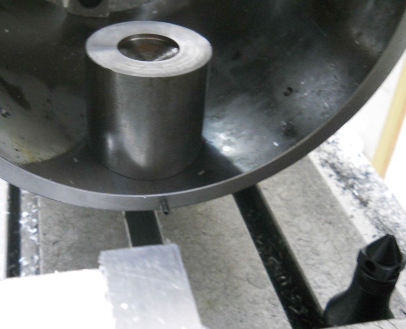
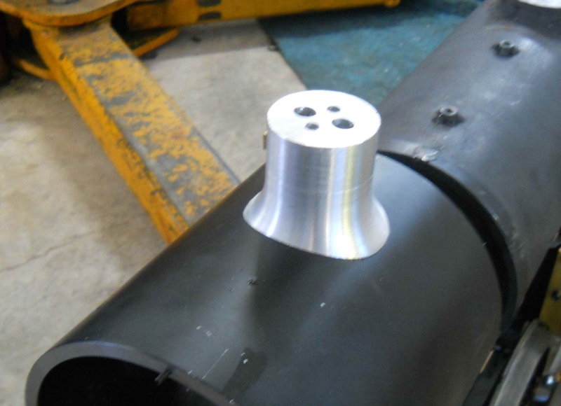
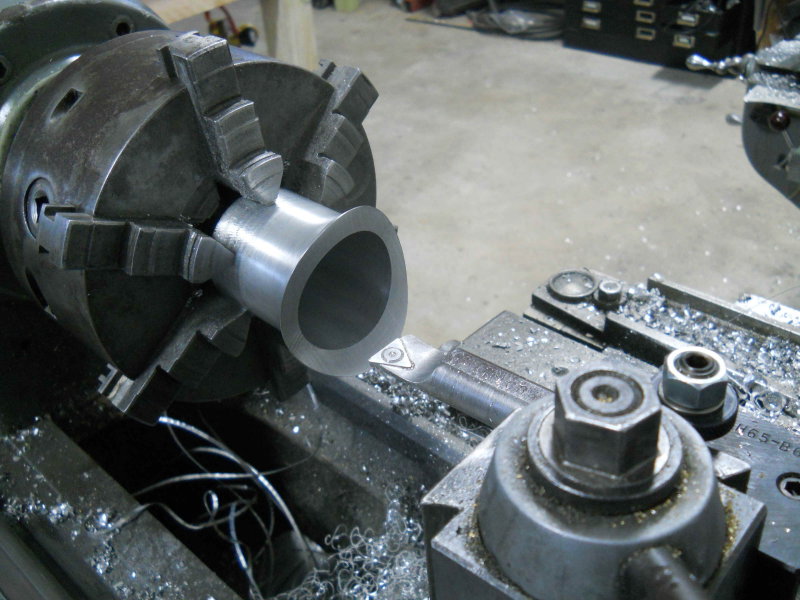
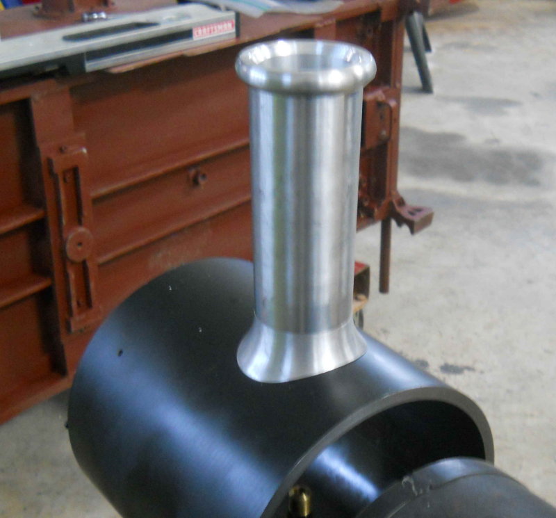
Next I wanted to find the height of the boiler's centerline above the top surface of the tee. I used a height gauge to measure the top plus a micrometer for the diameter and did a bit of arithmetic. Next I measured the OD of the smokebox using the DRO on the mill. Combining the two measurements allows computation of the length of the exhaust tube needed to support the smokebox and attached boiler to the tee.

large.jpg


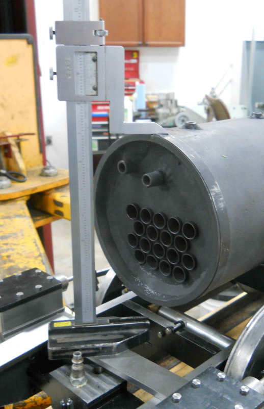
Notice that there are 18 3/4" copper flues vs. the 7 1" flues that Kozo shows. So my total draft area is 8 inches square vs 5.5.

Another difference is that the smokebox is a slip fit over the front of the end of the boiler and will be just sealed with high-temp RTV, vs. being clamped as Kozo does. This allows expansion of both when hot.
 
This is coming together real nice ... thanks for sharing. :)


Pat H.
 
Today I had a couple of hours to start on the smokebox. Raw material is a steel tube 7.3" in diameter and 15" long. I measured the ID as accurately as possible using edgefinder and DRO on the Bridgeport. Then I mounted my rotab on the mill for the first time in over 2 years. I centered it under the spindle with a DI, and then milled the outer ends of the soft jaws to match the tube's ID:

large.jpg


I then mounted the tube and turned the rotab 90 degrees in spot drilling 4 holes that will be tapped 5-40 and will be used to secure the smokebox door. With the rotab, chuck, tube, and drill chuck, I didn't have enough Z space to drill the holes, so I did this with the tube sitting on the vise.

large.jpg


Now I mounted the rotab vertically and squared to the table, then chucked the tube. I used the screws and a square to orient the tube and with an edgefinder to find the X axis centerline.

large.jpg


Finally drilled some "starter" holes for the smokestack and exhaust, plus two stanchions. That's as far as I wanted to go for now. I want to finish the smokestack base plus the petticoat so that they'll all get attached together. Those plus the exhaust nozzle are my lathe projects for the next shop sessions.
 
Wow, that is a thick walled smoke box. Is the boiler also steel? If so your engine will be a mini-monster! Do you have any idea how heavy it will be when completed?
 
Steam engines work better the heavier they are. The power of steam is such that the wheels will slip unless there is enough weight on them when pulling a load. Some builders in this scale use lead sheet for lagging around the boiler to increase traction. I'm guessing that when complete and holding water, the engine will be at around 200 lbs.
 
I've read stories about engines being loaded with slabs of lead to aid in traction, especially with the smaller gauge engines. That is one thing I will eventually have to think about doing the same on my engine as the design is apparently known for being light on its feet.
 
Today's small parts took more time than I care to admit, but at least there's progress. For the petticoat, I started with a piece of 2" round 12L14 steel. The first operation was to set up on the CNC mill to machine the end to match the ID of the smokebox.

large.jpg


Tested for fit:

large.jpg


Then onto the lathe to be drilled, and then bored to match the diameter of the smokestack. I have to give props to the new DTM boring bar and AXA holder I picked up at Cabin Fever. Perfect fit on the QCTP and very solid.

large.jpg


The brass item to the right is a roughed out exhaust nozzle. I need to make a bottom plate for the smokebox where the nozzle will set; the rounded end will be threaded and pass through the bottom of the smoke box to screw into the support bar. Hopefully I can make the plate next time out and get the smokebox sitting on the chassis for the first time.
 
kvom said:
Steam engines work better the heavier they are. The power of steam is such that the wheels will slip unless there is enough weight on them when pulling a load. Some builders in this scale use lead sheet for lagging around the boiler to increase traction. I'm guessing that when complete and holding water, the engine will be at around 200 lbs.

Kvom,

Is there provision for sand boxes in your design ???

Full size locos used them to drop sand on the rails to help stop wheel slip, particularly on wet rails, (rain, snow, dew and all the other slippery slimey things that lurk on the track.).

Best Regards
Bob
 
There's a dummy sand box. Pics of the fabrication start on pg. 17 of this thread. I'll need to remachine the radius on the base a bit to match the boiler cover.

Working sanders don't work well at this scale.
 
Today's target was to finish the exhaust nozzle and smokebox support and see how the smokebox sits on the chassis. After drilling and tapping the support bar 1/2-20, I single-pointed the bottom of the nozzle. Good fit:

large.jpg


I then did a quick CNC job to mill the smokebox ID radius onto a small piece of CRS, which I then drilled. This piece allows the nozzle to screw down flat inside the smokebox and provide a seal. Then I screwed all 4 parts together:

large.jpg


With the nozzle screwed down tight the smokebox sit quick firmly without rocking. It can obviously swivel side to side, but that will be eliminated when the steam pipe and saddle are added. The height looks to need adjusting. I think that will wait for later since I may need to adjust the grate supports to account for uneven welds on the bottom of the firebox wall.

With the boiler sitting in place, it's clear that any chassis work/rework needs to be done before trying to steam up as there is very limited access underneath. So since I have a laundry list of stuff to redo or fix, I'm planning to work on the chassis, smokebox, and boiler separately, not joining them until all the separate issues are addressed. I do need to tear down the chassis for at least the following:

1) Drill/bore hole in right side frame for blowdown valve access.

2) Drill and tap cylinders for cylinder cocks (I'm going to use some automatic ones at least initially).

3) Separate wheels from axles to address axle box oiling and replace one axle with a broken drill bit, then re-quarter drivers.

4) Finish and install foot brake system.

5) Add bracket/link on one eccentric trunion to drive lubricator

So I need to not get too "excited" about the boiler for now. The smokebox still needs the stack base made, and the stack/base/petticoat attachment figured out.

Lots to do
 
Today's shop session involved reducing 2 pounds of aluminum into a two ounce part and lots of swarf. This is for the base of the smokestack.

Started with some 3" round, faced both ends on the lathe, drilled and counterbored for two 1/4" mounting screws, and attached to a fixture plate.

large.jpg


Lacking a CNC lathe, the next best thing is milling the outer profile as a series of .003" cuts in Z.

large.jpg


Now mount on the lathe and use file and sandpaper to smooth out the layer-cake.

large.jpg


Next, drill and counter-bore two more holes to mount on the angle plate; then place the plate on the mill,

large.jpg


And mill the bottom face to match the curve of the smokebox.

large.jpg


Looks good so far:

large.jpg


Next, bore to accept the smokestack. I was shooting for a press fit, but overshot and got a tight sliding fit.

large.jpg


Part off, and assemble for another check.

large.jpg
 
Yesterday I decided unpack the pair of tender trucks that I purchased at Cabin Fever and then see about mounting them on the tender body. I discovered that the tender's bolsters were two long, and would hit the top of the brake shoes.

large.jpg


After seeking and receiving some good advice on Chaski, I decided to shorten them and add two mounting holes to replace those that would be cut away. Since the distance between the truck's center and the corner of the brake shoe was 4", I decided to mill the ends with a 3.75" radius via CNC. Here's the result:

large.jpg


I needed to drill and tap 3/8-16 in the tender bolster pivot to match the truck's kingpin, and after screwing the bolster back on the tender frame, it was straightforward to screw the trucks onto the bolster.

large.jpg


With the tender upright, I could check the coupler height; it's dead on for the IBLS standard. After towing it around the club track in the next couple of weeks to verify tracking, I'll need to do some more work on the tender before painting. The main task is adding a second water leg valve in order to support two injectors.

large.jpg


While I have both engine chassis and tender on their wheels, I'll measure to see how to make the drawbar to fit the two.

 
The tender looks as though it will fit the A3 perfectly! Have you lined the loco and tender together yet to:

A/ Get a good idea of the final 'look' of the engine?
B/ Get a photo to show the boards how impressive your future hauling machine looks?
C/ Sat behind it and pretended you're driving round a railway whilst making whistling noises? ;D

Hope to see more soon!
 
Before tearing down the chassis for some paint and fixes, I need to finish the brake system and test it. With a short shop session today before the super bowl, I decided to make the brake rod and its "fork ends" (pg. 214, fig. 3-9).

Having no 3/16 rod handy, I made the rod from 1/4 rod and turned down the ends to .190 for threading 10-24. The ends were profiled and slotted on the CNC mill from 1/2" square HRS, and then the ends drilled and tapped on the manual mill. Couldn't find a 10-24 nut for the jam nut though. I'd previously made the brake beam lever, but looking at it a year later I've decided it's crappy and will remake it. I have acquired a small metal bender that can make accurate bends in flat stock, so I'll be able to use that on the lever as well as the foot pedal.

large.jpg


We had a run day at the club yesterday where I was intending to tow the tender around to check its tracking. But since my hoist is occupied by the Jeep, and since the tender is now too heavy for me to lift now that it has trucks, I left that for another time. In the meantime I'm learning a lot about how to plumb the boiler from looking at other members' locos. I ordered some brass bar that can be made into the turret at some point. I also have on order some round-head drive screws that will become fake rivets around the ends of the smokebox.
 
Looking great KVOM! :bow:

Question....what's the primer your using in the photo...is it for copper/brass specifically?

I've never had good luck painting these metals.....always comes off easy.


Dave
 
Dear Kwom
You are doing a real masterpiece!! I'm really interested on you project!!!
Best regards
Paolo
 
Having seen quite a number of locos in "real life" since I started, I am a little ashamed of my puny efforts in comparison. I saw your thread start Paolo, and those drivers are great.

Lately I haven't been doing much for progress, other than odds and ends. I started making the fire door this week and still have a couple of pieces to go to finish it.
 
OK Kvom....I seem to remember the plans call for some copper smithing on the tender, and I just assumed.

Looking good! Stick with her , your getting near. :bow:

Dave
 
I didn't feel like doing any machining/fabrication today, so decided not to put off disassembling the chassis any longer. Now it's down to frame, drivers, and cylinders. Next step is to position boiler level on the firebox supports to determine the proper height for the smokebox supports. Since my lift has been occupied by the Jeep for the past 2 weeks, and likely another week to go, at least I can "probably" lift it down to the floor.

Once that's done it's coming apart the rest of the way. I need to bore a frame hole for the right side blowdown valve, paint the side frames, drill/tap the cylinders for cocks, and then paint the cylinders and steam chests. I will also drill and tap the steam chest covers for the lubricator check valves.

large.jpg


I also took the tender tank off the frame preparatory to painting. Now it's also in pieces that I can lift. I started painting the three removable covers, but will need more paint to cover all the rest. Paint is Valspar tractor paint.

large.jpg
 

Latest posts

Back
Top