Kozo A3 in 1.5" scale

Home Model Engine Machinist Forum

Help Support Home Model Engine Machinist Forum:

This site may earn a commission from merchant affiliate links, including eBay, Amazon, and others.
I had a desk like the one you got ,be careful that the wheels don't split out the side of the press board. I would hate to see it tip over and smash all your hard work. Dale
 
Very long afternoon in the shop to get ready for pulling the chassis around the track tomorrow.

I milled a bit off the yokes to eliminate the main rod rubbing, reassembled the pistons to their rods, then got the rods, crossheads, etc. all assembled. The chassis rolls quite well on the stand; this was the first time the piston were driven inside the cylinders since all the fitting was done with just the piston rods. Then I reattached the spring rigging. At that point the chassis was quite nose heavy, so I added the temporary running boards and a chunk of steel across the frame at the rear, plus screwed in the grate holders. With extra steel rearward, the chassis seems pretty well balanced.

I also decided that with the "stand" mounted on the lift arms, I might just as well use it as the transport too, since I can lower the stand and loco into the bed of the truck using the lift. So I added some eye bolts on each end to allow a ratchet strap to secure the loco to the stand during transport. Here's the result at end of day:

large.jpg


While not needed for testing the chassis motion tomorrow, I screwed on the steam chests and tops, plus the front cylinder heads to keep any dirt or dust out of the cylinders.

Yesterday I located a reducing bushing to adapt a 3/8-18 NPT male hole to a 1/4-18 female NPT fitting; a friend has a 3/8 tap that I'll use tomorrow to tap the supply hole in the tee, which I drilled out to 9/16 today. I'll need to do a pretty complete disassembly to install the tee as the frames must be separated. So the next assembly will have as its target to run on air. I need machine only 4 more significant parts, and the rest are pins and other fasteners.
 
Kvom,

That's just the "Ants Pants" ::)

I have never built a model loco but at 12" : 1ftwhen moving a loco from a.....b by towing it's always done with the cylinder drains open. I don't know what is fitted and what is not fitted inside your cylinders/steam chests but you don't want to over pressure them or lock up your wheels on the track.

Hope I'm not being a smart ass and that it helps.

Best Regards
Bob
 
Thanks for looking in, Bob. I have not as yet drilled or installed any cylinder cocks pending a decision on buy vs. build and type. I am leaning towards steam-operated cocks. The cylinder heads are on loosely, the o-rings in the packing glands are not there, and the rest of the openings are just covered with tape, so pressurizing is not an issue.
 
The on-track test run yesterday went pretty well. I pushed the chassis around the main loop (2 miles) without incident, so when I disassemble it I'll see if anything looks amiss. I did lose one of the spring gibs which popped off somewhere. These are simple and easy to remake. I was warned by another builder that this particular system wasn't ideal, but if/when I camber the spring packs the gibs should be more secure. Didn't get any pics as I was doing the run solo.

I also found that the "rails" on my stand are a bit too close together. The loco rolls on them fine, and unloading onto the lift was smooth, but reloading didn't work too well as the lift's track didn't line up well enough. I plan to move one rail out about 1/8".

I talked to another builder about fixing the oversize hole in the tee. I'm going to machine a round plug and press it in, then weld the seam, and finally drill/tap for a 1/4 NPT connector.
 
Started on doing a few simple things that always seem to take as much time as the big parts. First up was starting to fix the oversize steam supply hole in the tee following a club member's recommendations. I used an endmill to enlarge it and remove the cocked threads, then measured the hole with a bore gauge I bought a few months back and hadn't used until now. Then turned a steel plug .001" undersize and pressed it in using the 3-ton arbor press. After milling the top of the tee flat the joint for the plug is almost invisible, but my friend might want to tig-weld the edges anyway. After I'll drill and tap 1/4-NPT for an air fitting, and later a compression fitting for steam. That was the first time I'd machined a press fit steel on steel, so I was pretty happy with the result.

Then the simple spacers for the quadrant (need paint) plus the pin for attaching the reversing lever to the quadrant. I made this from brass rather than steel hopefully avoiding rust later on. The pin is retained with an e-clip on the other side.

large.jpg
\

Next I made the two square valve nuts; these are ~.5" on a side and drilled/tapped 10-32 to match the valve spindle. When I went to try a fit on the cylinder I discovered that the groove in the valve where the nut lodges wasn't deep enough by 1/8" *(I had misread the plans). So back to the mill to *(carefully) deepen the groove on both valves. Seems to fit well now.

large.jpg
 
Awesome! Looking good! I'm still working on my 3/4" A3 but I'm way behind you. I hope you get lots of video of your loco because there is a serious shortage for how popular the Kozo A3 is. Youtube has maybe 3 videos that I know of where you can see it running. 2 on test stands and 1 on track. Again awesome work!
 
Hi,

Very cool results... Lots of patience!

Cheers,

Alexandre
 
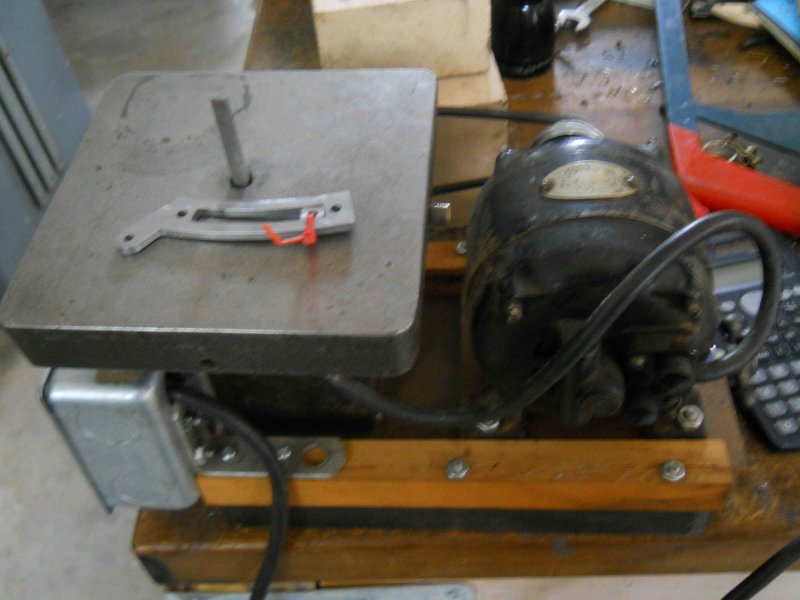
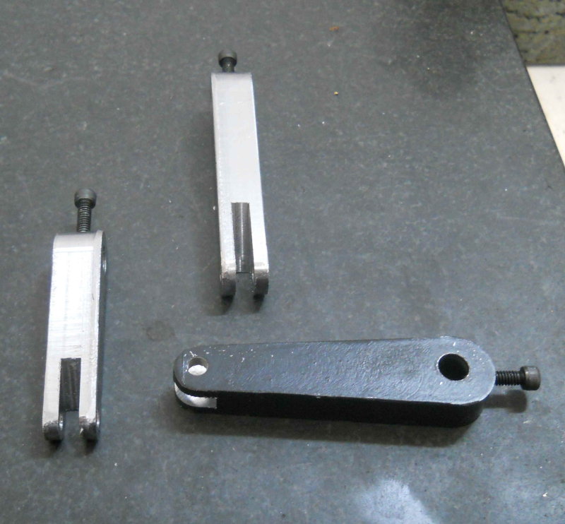
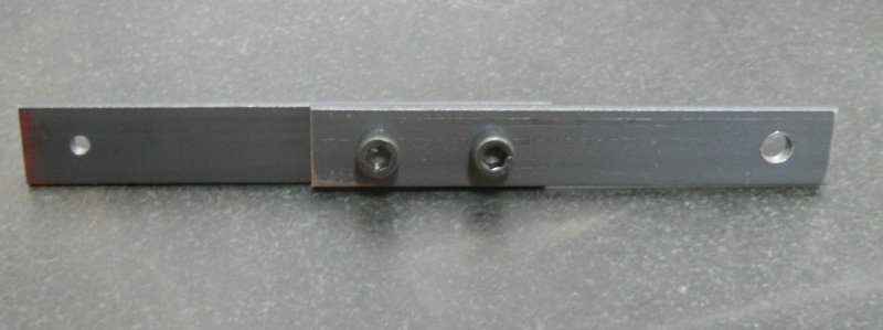
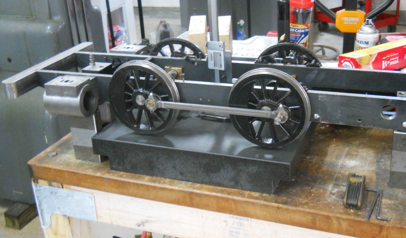
The work for the past couple of days was finishing some pieces to do a trial fit of the valve parts. First up was filing the ends of the slots in the expansion links square to the die block, to allow full-travel. I did the first one by hand, but then said to myself, "why am I doing this when I have that little antique die filer I bought a while back and have never used?" The second one went a lot quicker.

large.jpg


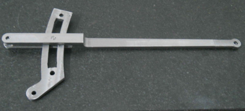
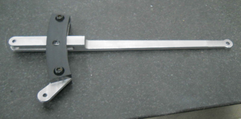
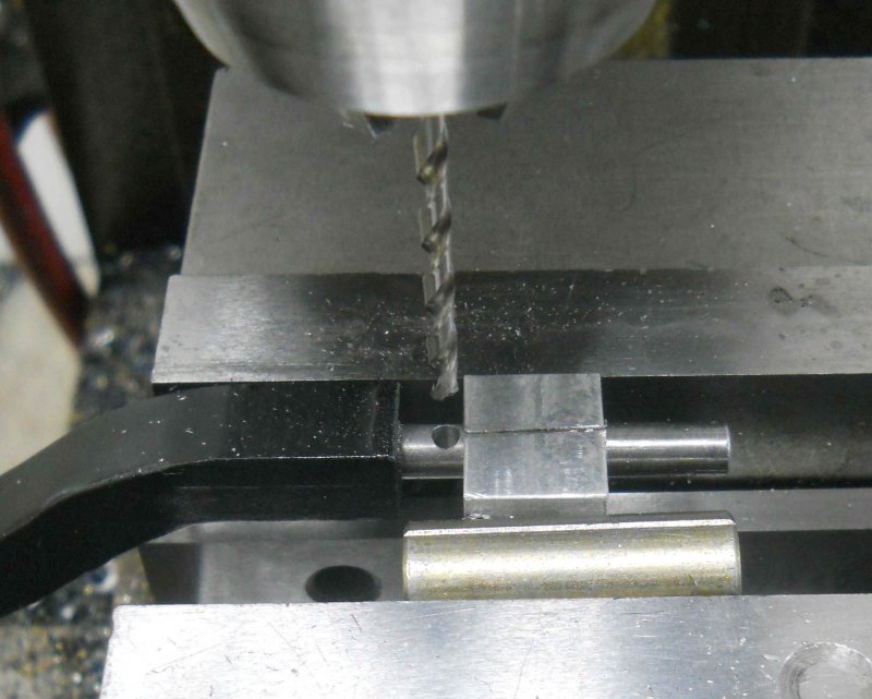
After quickly making a couple of pins, the expansion links and radius rods were attached.

large.jpg


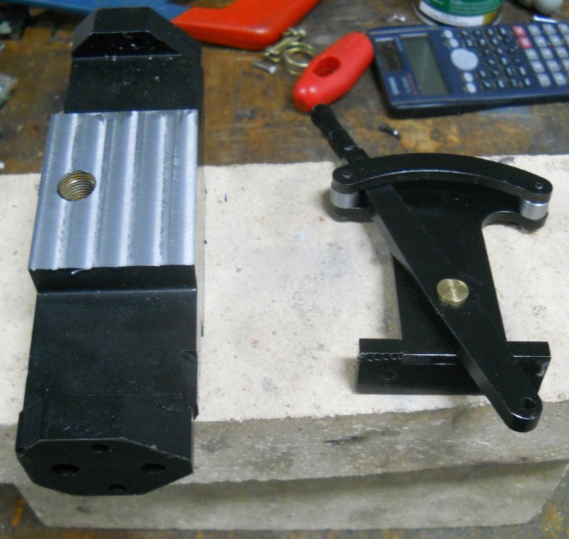
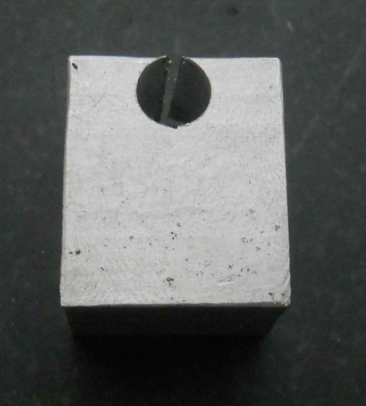
Then the trunions were screwed together, but the resulting assembly clamped the radius rod too tightly to move. Some experiments showed that it's the outer "arm" of the rod that's too thick, or the trunion is too thin. For the time being I inserted some thin washers as shims.

large.jpg


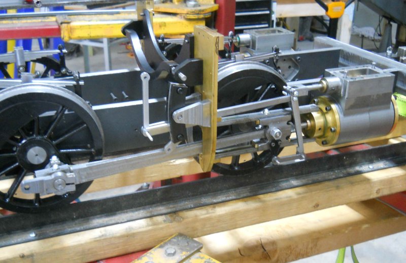
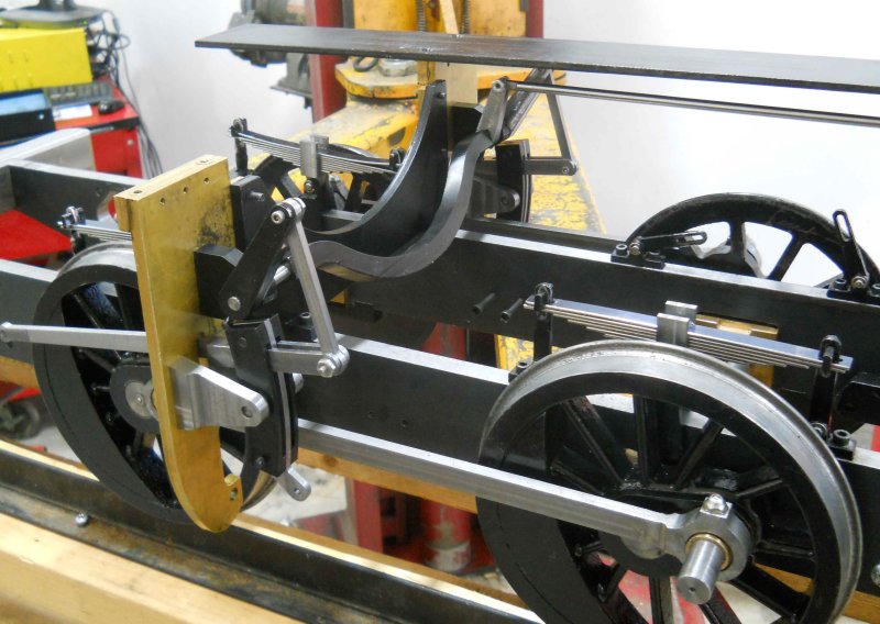
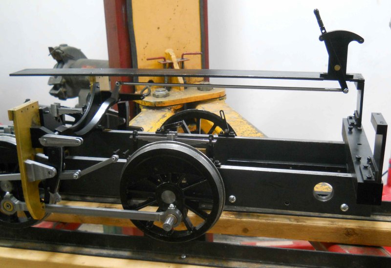
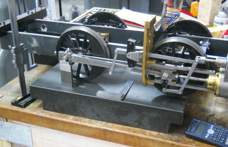
Now I tried to put it all together on one side, using some screws as the needed pins/e-clips aren't made yet. Most everything went together pretty well.

large.jpg


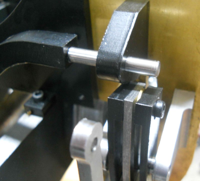
I found a few places that rub. The top of the inner expansion trunion just touched the bottom of the reverse lever bracket.

large.jpg


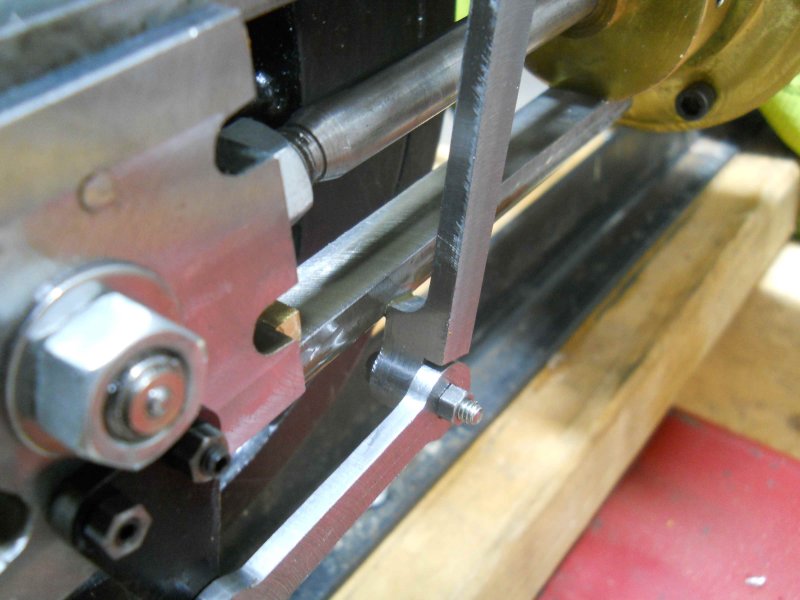
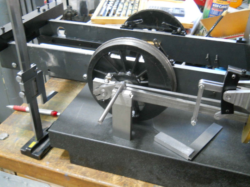
And the bottom of the combination lever rubs the lower crosshead guide (apparently a known issue with the plans).

large.jpg


I also found that the main rod was interfering with the inside trunion, and some examination shows that the spacer bushing on the rear crankpin is too wide, pushing the end of the rod out. I'll need to take about .050" off to correct the problem and get the main rods parallel with the side rods.

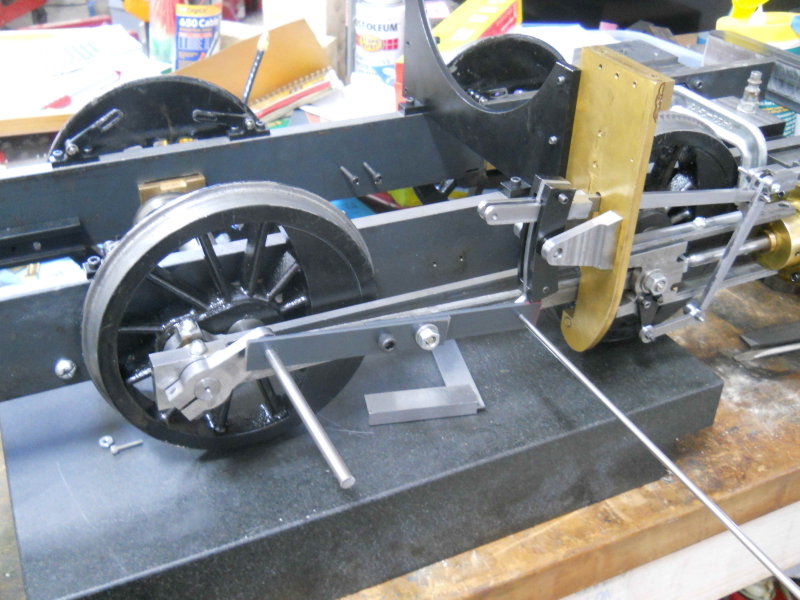
I took it all apart again. In addition to the above fixes I need to machine and attach the 3 reversing arms to the reverse shaft, plus make the temporary eccentric rod. The chassis-on-air goal is in view, but still lots to do.

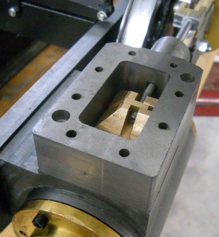
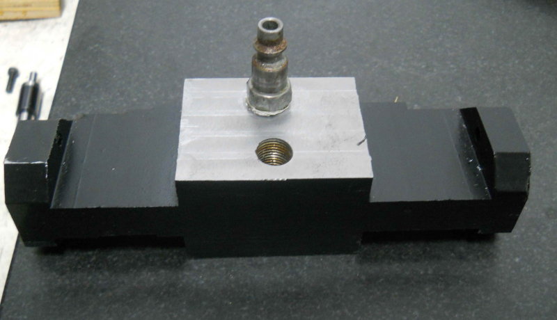
I had been wondering how hard it would be to adjust the valve nut in order to set the valve travel properly. It turns out that by unscrewing the steam chest from the cylinder the chest and valve rod can pivot up on the combination rod pin making the nut easy to access. Given 32 thread/inch and a square nut, a quarter turn of the nut gives an adjustment of 1/128" (.008), which ought to more than enough precision.
 
My order from McMaster arrived at noon: o-rings for the engine and a 1/4-18 HSS pipe tap. The rings serve as the packing glands for the piston and valve rods, and are made of Viton rubber. They come in packs of 100, and since I needed only 2 of each size I have a lifetime supply. Sizes needed are 010 for the 1/4" valve rod and 012 for the 3/8' piston rods. After installing the rods seem to slide as well as they did without, so we'll see if the rings seal as expected.

I decided to finish drilling and tapping the steam supply port in the tee now that I had the correct tap, so after drilling the hole in the plug (7/16" diameter), I found that the square end of the tap was too large for my small tap wrench. I jury-rigged a substitute by combining two wrenches, a 12-point box end and a standard. that could both fit onto the end of the tap. I used a dead center mounted in the mill to ensure the tap started straight, and with the wrenches pointing in opposite directions I could keep even pressure. With lots of tapping fluid and removing the tap a couple of times to clear chips, I got the tap to the needed depth fairly quickly.

large.jpg


I also got the eccentric trunions and combination lever issues fixed, but ruined one of the reverse lever brackets when the part slipped in the vise. So I plan to remake both with a bit of extra clearance for the eccentrics.
 
Over the past few days, I have been working on the reversing gear. The first task was to machine the two arms I hadn't already done. The smaller one attaches to the reach rod and thus to the quadrant lever. The longer two are connected to the radius rod by the hangers.

large.jpg


I had disassembled most of the drive gear from the chassis, so I replaced the yokes on the tie plate and mounted the eccentrics. Then mounted the reverse arms on the reverse shaft at the distance from the shaft's center indicated by the drawing:

large.jpg


I attached the assembly to the yokes and was happy to see that the reverse arms, hangers, and radius rods all lined up.

large.jpg


Now it was time to drill the mounting holes for the three arms into the ends of the shaft using the angular positions show on pg. 114, fig 18-20 of Kozo's book. I needed a way to hold the shaft at specific angles, so I decided to make a little collet clamp from a piece of aluminum.

large.jpg


I drilled the hole .01" from the edge and cut the slit with a coping saw.

I could set the necessary angles using angle bars against the sides of the shaft, and then clamp the rod tight in the vise. Then it was just a matter of setting the position with the DRO and edge finder and drilling the holes.

large.jpg


Remounted on the yokes, it was time to set the reach rod. I had to cut off a few threads on the far end to get close.

large.jpg


With the reversing lever all the way forward, the reverse arms are supposed to be horizontal. I had to remove the spacers on the quadrant to get the necessary full range shown on Kozo's drawings. If I lengthen the reach rod to avoid this, then the neutral position is away from vertical. I'll wait until it's time to set the valve timing before seeing what's needed for full forward and reverse. For now it's pretty close.
 
Hi Kvom
Its looking great !
:bow: :bow:
Pete
 
Now I need to continue finishing up lots of little stuff before it can run on air. The only large parts to do are the eccentric rods, but these can't be completed until I know the exact distance between the rod ends, and this distance must be measured precisely once all the rest of the valve mechanisms are adjusted. The measurement also needs to be done separately for each side. To do the measurement, a temporary adjustable eccentric rod is needed, so that's one of today's projects. I made it from two 4.5" pieces of .75x.125" steel bar.

large.jpg


The screws are .25", and in one of the bars there are slots allowing the total length to be adjusted +/- .10". The holes on the ends fit into the pins on the return crank and the the eccentric. When these two pieces are positioned correctly, I put on this bar to fit and tighten the nuts to lock in the length. The bar then serves to measure the distance between holes drilled in the real eccentric rod.

I also made a brass plate to seal off the bottom of the steam supply hole in the tee. Under steam, this plate will be modified to connect to the lubricator and admit steam oil, but I'm not ready to make that yet. I chose brass so that the steam oil conduit can be more easily silver soldered.

Finally, I wanted to start to smooth the top of the cylinders where the valve slides. Kozo recommends wet sanding with 400 grit wet/dry paper, which I lack. So instead I sanded the valves using different grades of paper through 320, and then a final pass with 600. Tomorrow I'll try to get some large sheets of 400, plus some coarser grades to start. It would be nice to surface grind these, but paper will have to do. Rather than try to do a lot of sanding on the fit between the ends of the tee and the cylinders, I plan to install gaskets here even for air.

My 5/32 drill rod also arrived from Enco today, so I can also start making the pins for joining the valve gear components.

As Jack Bodenmann says, no lack of things to do.
 
The past couple of shop sessions were devoted to tearing the entire chassis down to individual pieces so that I could get the tee between the side rails. Then I could attach the cylinders to both the tee and frame rails. I made some gaskets from a fiber sheet I purchased at Ace Hardware, and coated both sides of the gaskets with anti-seize, this being on the advice of a fellow builder.

With that done I could start to put things back together, this time sitting on my surface plate that would be needed subsequently.

large.jpg


With the valve gear and rods installed, the first part of valve tuning is setting the return crank. To do this, the crank pin needs to be at dead back center. I measured the wheel diameter with the height gauge as well as the diameter of the crank pin, and was thus able to calculate the necessary height of the bottom of the pin above the plate. Using gauge blocks to make up this height, I moved the chassis until the crank pin was pressed against the blocks.

large.jpg


I locked the chassis in this position by clamping the front driver, placed the return crank on the crank pin, and rotated it until the 1/4" pin was pressed against a second stack of gauge blocks. The center of the link pin is supposed to be directly above the center of the axle. Since I knew the distance between the holes in the crank and the distance of the crank pin center and the axle center, a bit of trigonometry yielded the height of the gauge block stack.

large.jpg


After tightening the clamp screw on the return crank to lock it in place, I now used the temporary eccentric rod to attach the crank to the eccentric.

large.jpg


Now I followed Kozo's instructions to position the eccentric such that moving the radius rod up and down fully causes no movement in the valve. Once I had a good position I could tighten the lock screws on the temporary rod. I then measured the distance between the rod's holes by clamping the rod in the mill vise and using the DRO. Doubling Kozo's estimated length gives 6.054", while mine measures to 6.148". Given that my wheels are slightly larger than Kozo's scaled plus all other machining variances possible, I'm pretty happy with the result. The same measurements need to be done on the other side next time out as the length is likely to be slightly different.
 
That is real pretty Kvom, gerat work as usual.
Brock
 
Kvom,

Wow :bow: this is coming along great guns and pretty fast as well :bow:

Best Regards
Bob
 
I declared victory on the eccentric rod too soon. In addition to the radius rod not moving the valve, the pin attaching the eccentric to the rod needs to be close to level with the axle center. Since the 3/4" scale model has no springs, the axle can't move relative to the frame and eccentric, so there's no problem. However, the 1.5" scale has springs and sliding axle boxes. My setup was without springs, so the frame slides to the top of the axle boxes leaving the eccentric pin lower than the axle center.

I measured the height of the eccentric pin center with the temporary eccentric rod installed, and it is .182" lower than the axle. The obvious solution would be to try to raise the frame .182" and remeasure with the temporary rod. However, since the eccentric itself would be in the same position relative to the valve, I realized I could use trigonometry to solve for the new value, which turns out to be 6.124".
 
Excellent Kirk,A really nice job
Don
 
I got some shop time this afternoon, so it was finally time to work on the pins for the valve gear (p. 108 in the book). These seem to be more finicky for me than they should be, but I did manage to make four for the one side I have assembled plus one for the other side. I really should have soldiered on, but my feet were telling me I'd been standing too long. The e-clips for the union link were a PITA to attach on the inside where they belong, so I reversed them for the time being. Better to pre-assemble these, which I'll do on the left side build-up.

I discovered that "somehow" the pin for the left side valve spindle had been drilled 3/16 rather than 5/32 like the right. These are the parts my daughter helped make a while back. So I just enlarged the matching holes in the combination rod to match and remake the pin with 3/16 drill rod.

7 pins to go, so hopefully I can speed up and get them all done the next time in the shop.
 

Latest posts

Back
Top