Kozo A3 in 1.5" scale

Home Model Engine Machinist Forum

Help Support Home Model Engine Machinist Forum:

This site may earn a commission from merchant affiliate links, including eBay, Amazon, and others.
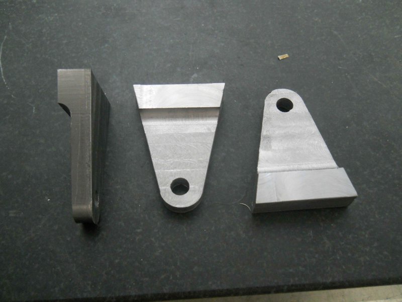
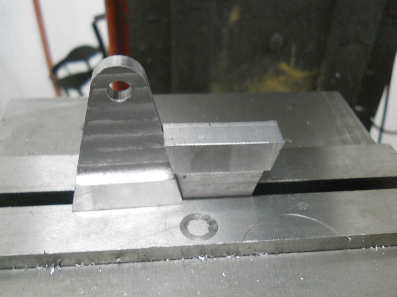
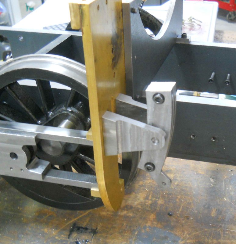
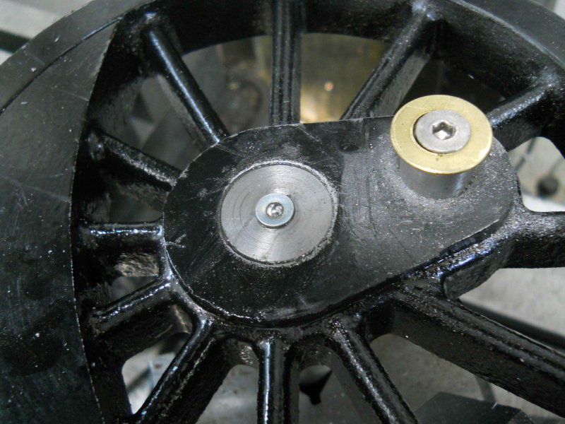
I made the doodads for attaching the expansion links to the yoke brackets, and then decided to attack the "bad" crosshead in an attempt to save it. I drilled out the crooked threads, tapped the new hole 7/16-14, and secured a 7/16-14 bolt in the new hole with red loctite. Also used red loctite to secure screws in the bad 5-40 holes. After a couple of hours cure, I used a hacksaw to cut off the three screws and milled the stubs flat.

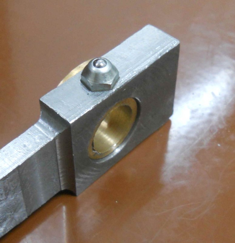
Next I re-drilled and tapped the 5/16-24 hole for the piston rod connection, this time using my nice new HSS tap. All looks OK.

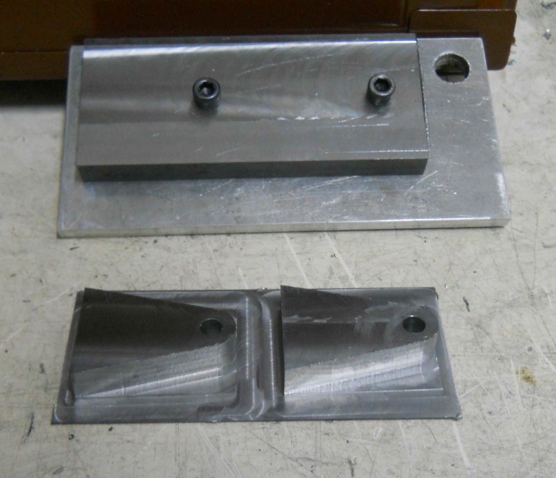
Then I cut some 1/8" brass to use for the crosshead slippers.

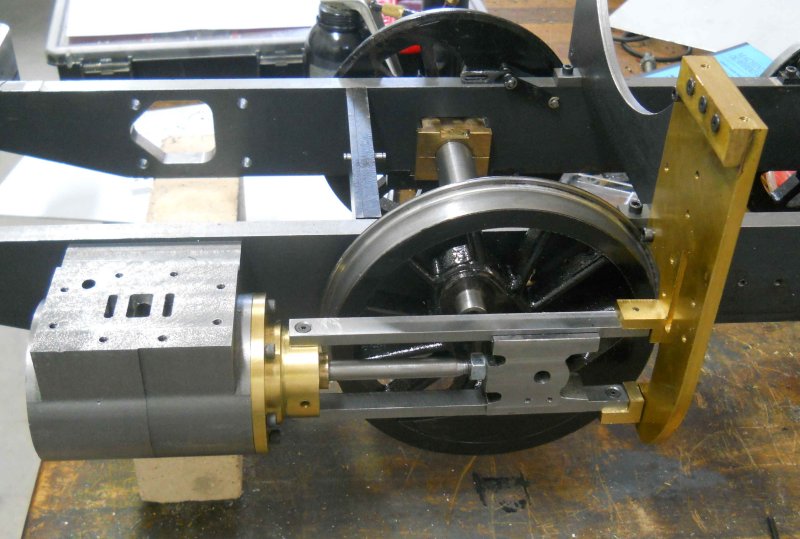
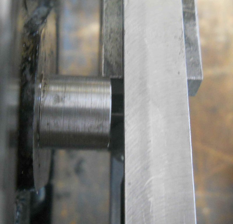
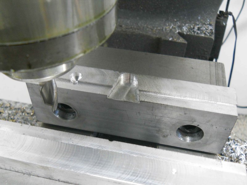
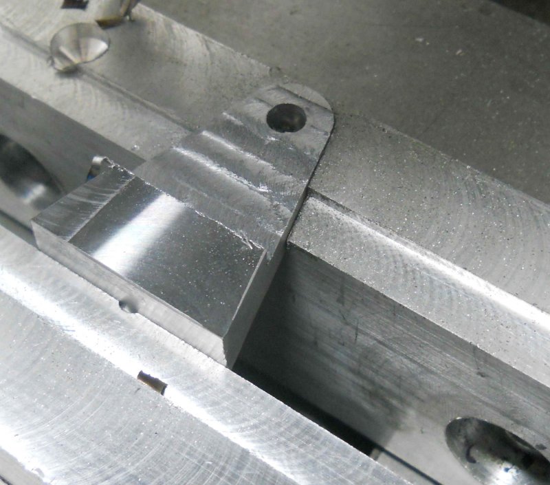
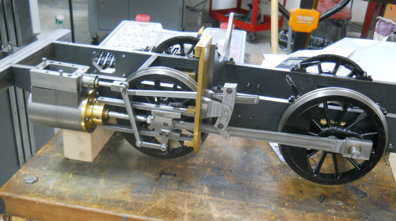
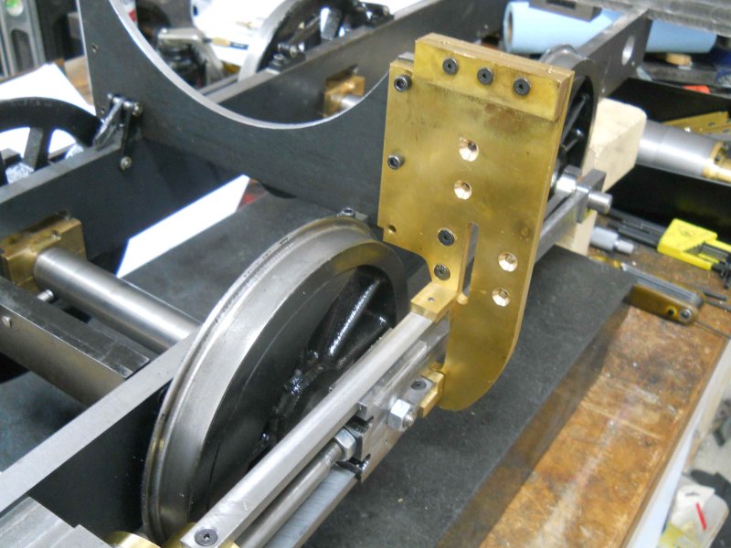
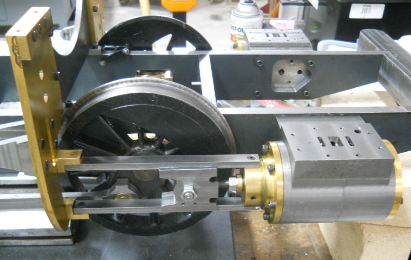
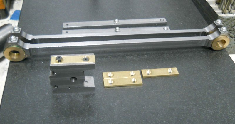
Finally started to try to fit the left crosshead to the guide bars. I used Kozo's method to mill the channels for the guide bars, using the piston rod on parallels to ensure that both channels are parallel to the rod. For this I had to take the piston off the rod. I milled the slots to match the bars without slippers; Once I get a decent fit this way I can deepen the channels by the slipper thickness. The first try afterwards fitting the cylinder, head, guides, and crosshead to the yoke ended up being too tight for the crosshead to move. Measurement showed that the yoke side bars were over .015 closer than the cylinder side, so it appears my mounts weren't measured as good as I thought last week.

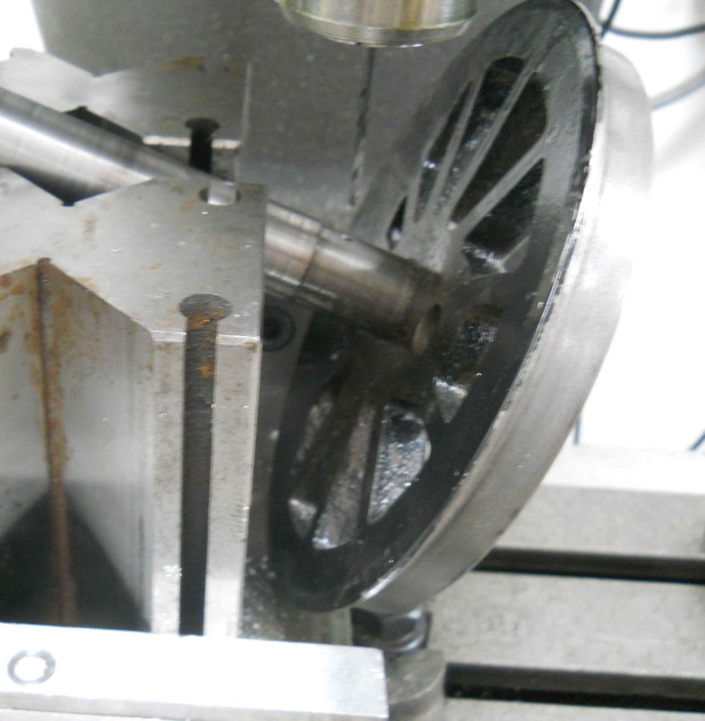
My immediate goal is to get the first crosshead adjusted properly fore and aft, and then I can see how much I need to narrow it or elsewhere to avoid hitting the front crankpin.
 
Spent a good amount of time milling the first crosshead and guide bars to allow the head to slide on the guides freely. They're still a bit tight at the rear so a few more thou clearance seems to be needed. The crosshead doesn't have slippers yet, but once it move freely on the guides then milling the slots to adjust for them should be straightforward.

large.jpg


With the guides and crosshead pretty close to good, I was able to investigate how much the front crankpin interferes with the crosshead. With the wheel tight against the axle box the pin just clears, but at maximum side play I get this:

large.jpg


I measured the side play as .071", so I plan to shave .080 off the pin and crosshead between them, and the same amount from the front end of the side rod bushing as off the pin.

I also did a quickie lathe job to make the bronze bushings for the main rod's small end, now that I have made the pin's diameter at 5/16". The next re-assembly I'll try to get the side and main rods attached and check the full range of motion.
 
Looks good Kirk. I'm glad you were able to save the cross head.

Looking more like loco each update.

I silver soldered bronze slippers on my Simplex cross heads too. The plans called for case hardening the cross heads but I don't have the equipment for that right now.

Ron
 
Rather than disassemble and mod the crossheads/crank pin, I decided to go ahead and make the link brackets and link blocks, so that I could test the fits there. For the link brackets, they are CNC'ed two to a fixture so that the two holes are present to secure the stock to the fixture.

large.jpg


Then I machined this pocket into a soft jaw:

large.jpg


The pieces are separated and held in the pockets to remove the excess from the bottom, and then to mill the relief cuts.

large.jpg


I ended up with 3 after screwing up one via a brain fart.

large.jpg


So I need to remake the others and then drill tab the mounting holes, but that's for another day.

While the above process is straightforward, I spent the entire afternoon on these as I needed to revise my programs a good number of times. The remake should go quicker.
 
Kirk

We are probably guilty of not giving you enough credit with your work here. Its some amazing stuff, and you keep churning it out.

Fantastic

Pete
 
I finished up the expansion link brackets by drilling and tapping the mounting holes. Here's a technique for making sure they're vertical in the vise:

large.jpg


Trial mount on the yoke with the expansion link assembly. It rocks very smoothly.

large.jpg


So I decided to do a trial fit of a lot of the made parts, holding them together with some screws:

large.jpg


Nothing looks too out of place, although I need to have a few more parts made before I can check the full range of motion with everything connected. Assembling everything is quite a puzzle as to the order needed. For example, with the wheels installed the bottom mounting screw for the yokes are inaccessible:

large.jpg


And as well the crosshead pin that holds the main rod can't be inserted.. On the other hand, the side and main rods can't be installed with the yoke mounted. So it seems that the tie plate needs to be removed, install the rods, then bolt the yoke to the tie place and install the pair as a unit. Still some experimenting to do.

In any case, I took it all apart, took .030" off each side of the crosshead and .020 off the side rod bearings and reinstalled as a check. Still some interference between the front crankpin and the crosshead, so the next task will be to shorten the crankpin.
 
Looking Great Kvom!

Nice trick with the parts in the vice!

Dave
 
Pete is absolutely right Kirk. This is quite a complex bit of kit, as your temporary build illustrates, making your progress so far even more deserving of our applause. Keep up the good work. Oh, and thanks for the tip.
Cheers Les.
 
With other commitments this week, I got only a few hours in the shop the past few days. The first order of business was to get the right side crosshead and guides lined up properly with clearance for the crankpin. This went a lot smoother than the left side.

large.jpg


I also wanted to provide an oil supply for the front axle bearings. This would have been done much, much easier had I considered it before mounting the drivers to the axle. Holding the axle and drivers on the mill was a problem, but I finally came up with this setup for the 3/32" radial hole:

large.jpg


Then drilled a hole down the axis to meet as well as a 1/4" hole for the ball oiler:

large.jpg


Unfortunately when doing the other side the drill broke off in the axial hole, so I'm not sure what I can do about getting it out.

I then installed one of these oilers onto one of the main rods:

large.jpg


These are threaded 1/4-32, so I had to order the tap along with the oilers from McMaster. I plan to use these on the side rod ends as well as the top guide bars once I tear everything apart the next time.

The next tasks in view will be to fit the slippers to the crossheads and make the link blocks. With those done I can contemplate mounting the full valve assemblies on both sides and possibly towing the chassis around the club track once again.
 
The "easy" solution will be to remake the axle, as it and the crank pins are just fixed with green loctite. However, I don't currently have the necessary big v-block with a clamp to redo the quartering.
 
Drilling intersecting holes always seems to be the culprit. I have yet to see any surefire tips on how to accomplish it without drill breakage. If you cant stuff something removable in the first hole I tend to just pray and go very slowly when the drill is about to break through.
 
A short session in the shop this afternoon resulted in this

large.jpg


I mounted the screw in ball oilers on both side rods, the top guide bars, and the other main, plus drilled and countersunk the brass slippers. Then drilled and tapped the slipper mounting holes on one crosshead. Although the 5-40 screw heads are countersunk, I think brass screws, if I can fine them, would be superior.

Hopefully I can finish fitting the slipper to both crossheads next time out.
 
Hi I beleive that your brass slipper are to be set dipper so that it will stay on your guide bars .Please let me know . I am also building this engine . Dale
 
dalem9 said:
Hi I beleive that your brass slipper are to be set dipper so that it will stay on your guide bars .Please let me know . I am also building this engine . Dale

That's correct. The crossheads currently have the slipper channels at the correct depth to match the guide bars. So for each I can measure the distance between the bottoms of the slots, and shoot for the top of the slippers being the same distance. Since I made the slippers from .125" brass sheet, my original intent was just to machine each channel .125" deeper. However, checking the drawing dimensions makes the clearance with the inner cavity a bit thinner than I like. So I plan to reduce the thickness of the slippers to .08" in line with Kozo's dimensions.
 

Looking good Kirk. I agree that brass screws would probably be better.

I was going to use screws like you did but I don't have anything smaller than 2-56 taps so I silver soldered them on. I hope I don't regret that choice later.

Ron


Latest posts

Back
Top