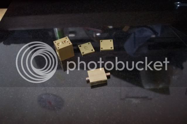
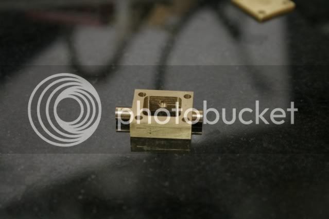
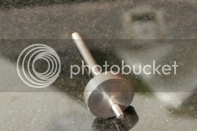
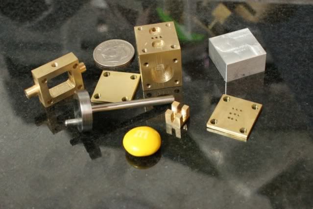
Elmer's #6 -- Slider, a slide valve engine

Home Model Engine Machinist Forum

Help Support Home Model Engine Machinist Forum:

This site may earn a commission from merchant affiliate links, including eBay, Amazon, and others.
Ok, time to get back to the engine. It’s another cold one here in the Midwest so I didn’t spend much time in the shop. For those that looked in on the vise stop build this is what I needed it for. I put the clearance holes in the valve and cover plates.

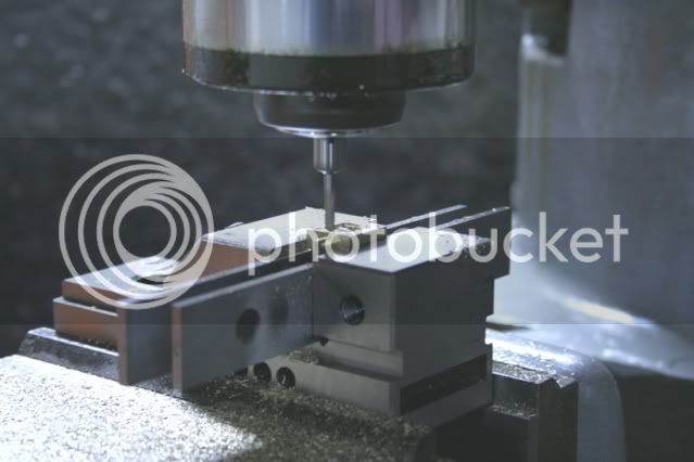
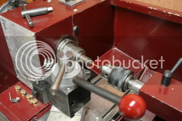
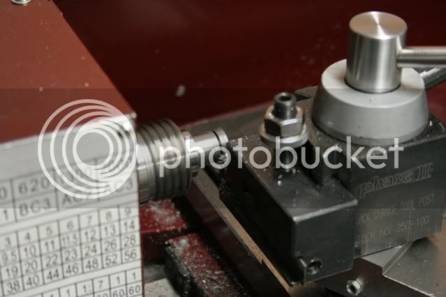
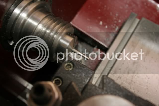
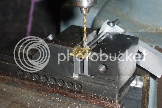
The part to be drilled was set up on parallels and indicated in using the edge sticking out and the fixed jaw of the vise, there wasn’t enough of the part sticking out to get the edge finder on it. The vise stop was also set in place and tightened down.

tn_e6_plate_1.jpg


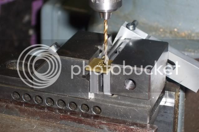
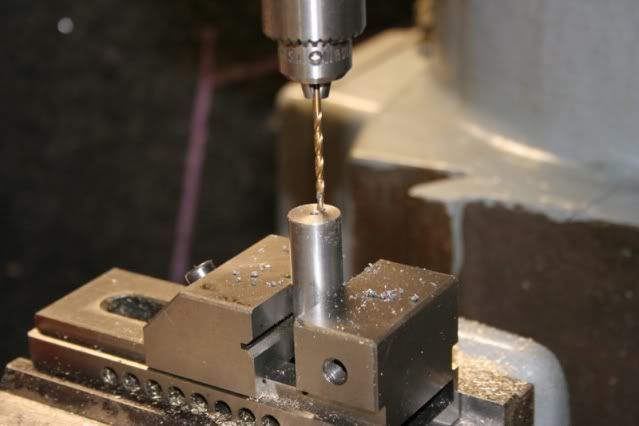
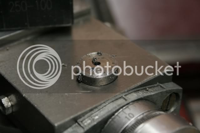
Once the hole was located it was a simple matter of drilling it.

tn_e6_plate_2.jpg


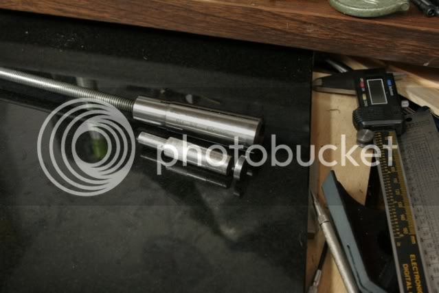
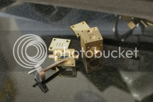
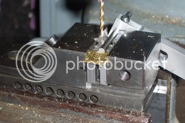
Here is where the stop came in handy. The part is symmetrical, the holes are in the same place relative to the corners. Once a hole is drilled the part is simply flipped and placed against the stop and the next hole drilled.

tn_e6_plate_3.jpg


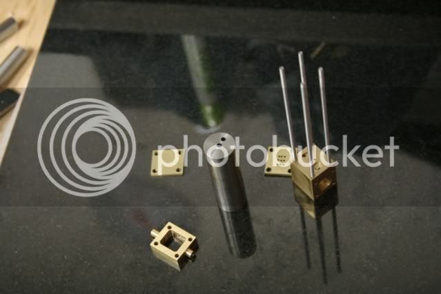
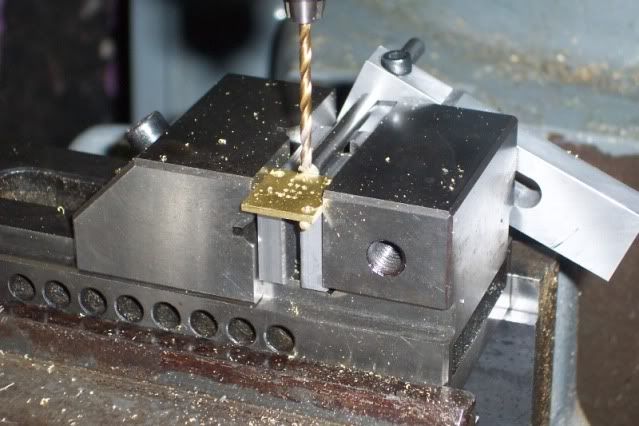
The part is then flipped again for the next hole, and so on till all are finished.

tn_e6_plate_4.jpg


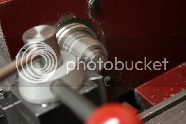
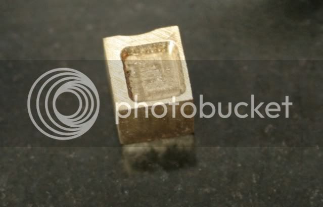
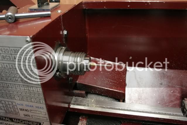
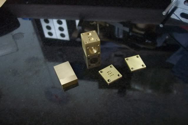
I also cut a piece for the steam chest and fly cut it to size. Next job is some 4-jaw work on the lathe. I get to work in heat for a change. Yes!

tn_e6_cyl_9.jpg


Thanks for looking in.

 
Your parts look good, Kevin.
Nice demonstration of the vise stop in use, too.

Dean
 
Thanks Dean.
Just tellin' the story for posterity so when I'm old and feeble my wife can read it back to me as she wipes my chin ::)
 
ksouers said:
Just tellin' the story for posterity so when I'm old and feeble my wife can read it back to me as she wipes my chin ::)

What you too.
LolLolLolLol.gif


Seriously Kevin nice work and the scale is pretty small. Your eyes must be pretty good for an old guy ::)

Best Regards
Bob
 
Nice work Kevin. Thm: I'm with Bob - impressively small scale for my eyes. For reference sake, what size are the holes in the 3 x 3 grid?

Cheers,
Phil
 
Maryak said:
Seriously Kevin nice work and the scale is pretty small. Your eyes must be pretty good for an old guy ::)

Bob, thanks for stopping by.
Uh, I use several cheaters of various types :D


Philjoe5 said:
Nice work Kevin. Thm: I'm with Bob - impressively small scale for my eyes. For reference sake, what size are the holes in the 3 x 3 grid?

Phil, thanks for looking. The grid is #57 (.043) sized holes, .100 x .0625 center-to-center from each other. The entire grid is .200 x .125 on a side.


I can see things well enough most of the time. My biggest problem is holding onto the bloody things. I'm always dropping something then it's a scramble to find where it bounced to. ::)
 
Not much done on the engine today. But did get to spend most of the day in the shop. The mill got trammed and lubed. Since the vise had to be removed that led to a few general maintenance projects. It was still a good day in the shop.

After getting the mill squared away I spent the rest of the afternoon in the heated shop doing lathe work. The steam chest has two spigots turned on the ends with holes drilled through them. One hole is where the valve rod enters the chest and a longer one opposite for a guide for the free end of the rod. The rod guide spigot is supposed to be a blind hole, but I drilled it from the end. I’ll close it later with a plug that will be soft soldered in and finish it off with a file.

The steam chest is rectangular and the holes and spigots are off center, so this was a job for the 4-jaw. The 4-jaw is set up in the C2. A pump center is used to get the part lined up. The part was marked up earlier and the centers for holes punched. The pump center is just a length of 3/8 drill rod (silver steel) that has a sharp point on one end and a small center drilled in the other. The point rides in the punch marks made earlier, the other end is held by a dead center. As the chuck rotates it moves the end of the rod around, this is measured with a DI.

tn_e6_chest_1.jpg


Once a hole was drilled it was time to turn the spigot. There’s a couple things going on in this picture. To the right of the saddle is a holder for a dial indicator. The cutting tool is touched off on the end of the work piece, then the indicator is moved in compressing the plunger enough to measure the length of the cut and locked down. The saddle is advanced the length of the spigot. On the left side of the saddle is a stop. Once the saddle is in place the stop is moved up against it and tightened down. I can now make the repeat cuts to bring the spigot to diameter without worrying about the length of the cut.

tn_e6_chest_2.jpg


The part was then turned around and whole process repeated. The remaining rectangular part is supposed to be the same dimensions as the valve face on the cylinder block. I ended up .003 too long. Close enough for gummint work. ;D

tn_e6_chest_3.jpg


Tomorrow I’ll finish it off in the mill. Several holes need to be drilled and the center milled out. Then we’ll see what other jobs I can get done.
 
ksouers said:
One hole is where the valve rod enters the chest and a longer one opposite for a guide for the free end of the rod. The rod guide spigot is supposed to be a blind hole, but I drilled it from the end. I’ll close it later with a plug that will be soft soldered in and finish it off with a file.

Kevin,

It's also a possible to mount a displacement lubricator on the guide rod spigot, instead of closing it off.

Best Regards
Bob
 
Nice bit of work, Kevin. I laughed about that .003" over part. If it were really gubment work, it could be 3" over, and you could tell everyone it was a good job.
; )

Interesting idea from Bob, that one about the lubricator.
 
Bob,
Good suggestion there! Yes, it would be the perfect place for it. Hopefully other readers will take note. This engine will be run strictly on air, however. It's intended as a gift for a friend who is into model railroading, but he hasn't a clue about how steam engines work. Hopefully by having one in his hands to play with he will understand. He's an engineer type so I'm certain he'll have it apart within 5 minutes of my being out of sight :D


Dean,
...And it would have been made out of wood. ;D
 
I got back on the steam chest today. I drilled the clearance holes for the studs and drilled and tapped the inlet and milled out the center portion. I didn’t want to take a chance on hitting the parallels so I milled a little more than half way through then flipped it over and finished from the other side.

tn_e6_chest_4.jpg


tn_e6_chest_5.jpg


Then I started making the crank disk out of 4130 steel, just because it was handy. I cut a short piece and chucked it up in a collet on the 9x20. Faced it and drilled the center hole 3/32 for main shaft.

tn_e6_disk_1.jpg


The part was then moved to the mill, centered vertically, and the offset hole for the crank was drilled, also 3/32. That’s as far as I got before my back gave out.

tn_e6_disk_2.jpg


I also cut a couple pieces of 1/8 inch 303 stainless to finish off the crank, but that’s going to have to wait till tomorrow.

tn_e6_group_1.jpg

 
I finished up the crankshaft today. I started out by parting off the disk from the parent stock. Using the parting tool always increases my pucker factor, reminding me of a metaphor about a straight pin and a sledge hammer.

tn_e6_disk_3.jpg


It was successful. No shorts were soiled today. Here is the part with the back side ready to be cleaned up.

tn_e6_disk_4.jpg


Doing something this short requires a little backup. In this instance a short piece of aluminum stuffed inside the collet behind the part. The draw bar adjusts how far the part sticks out the front. I have enough extra length on the draw bar to make this possible.

tn_e6_spider_1.jpg


Here it is in use, the back side of the disk is being faced off.

tn_e6_disk_5.jpg


Now it’s time to turn the bearings. The main bearing is just a piece of 1/8 inch rod with a for section turned down to 3/32 that plugs into the disk. The throw bearing is turned down to 3/32 it’s full length. Here is the throw being turned.

tn_e6_crank_2.jpg


And a finished crankshaft. The pieces are a very tight press fit and locktited into place.

tn_e6_crank_done.jpg


I also got started on the D valve. I cut a piece of 1/4 inch square brass and cleaned up the ends on the mill and brought it to size. It was now time to mill out the pocket. I used a 1/16 inch end mill and went round in circles a couple times. Seems it was also time for a stuff up. When it was done I found my math was a little off. This thing is so small I can’t see what’s going on. All I can do is read the DRO and only later do I find the mistake.

tn_e6_dvalve_fup.jpg


It’s starting to look like a collection of engine parts.

tn_e6_group_2.jpg


Thanks for looking in.
 
Yes, it does look like engine parts, Kevin!
I keep forgetting the size, until you mention something like the crank journal being 1/8" diameter. You need M&M's for scale.

Too bad about the goof. That happens to everyone, unless they don't build anything.
You deserve some cheaters so you can see what's going on. ; )

Dean
 
Deanofid said:
Yes, it does look like engine parts, Kevin!
I keep forgetting the size, until you mention something like the crank journal being 1/8" diameter. You need M&M's for scale.

Too bad about the goof. That happens to everyone, unless they don't build anything.
You deserve some cheaters so you can see what's going on. ; )

Dean

Thanks Dean.

I'm not worried about the stuff up. It certainly wasn't my first ::) Nor the last.
Just another part to be made, that's all.

I've got lots of cheaters. It's the getting old part that I need to cheat on...

The trouble I had with this part was (well, other than my math mistake) line-of-sight. The end mill is so tiny that the work is hidden under the mill head. I don't have direct sight of the part, it's just a little golden spot in the middle of the vise tucked way up under the spindle somewhere. I even extended the quill a bit to try to get a better view. It did help some, but the angle is still bad. Also the pocket just holds chips, in short order the tool is just moving through a pile of chips and somewhere at the bottom of it some work is being done.

I don't want to sound like I'm blaming the machine or the part, I'm not. I screwed up the offsets. All the other stuff just makes it awkward is all.

But I don't really need to see it. All the info is on the DRO. If only I had calculated the offsets correctly the pocket would have been where it was supposed to be. Ah well.

Yeah, I'm going to have to find a size reference. I think an M&M is probably too big. Do they still make tic-tacs?
 
Kevin, Your build is coming along nicely. Don't feel bad about the little milling mistake. It's happens to me more times than I'll ever admit. I concentrate on reading the hand wheels and counting turns. I cant see, or bother to look at some of the small stuff till it's over. And once in a while, "OOPS, the end mill just went out the side!" :big:

-MB
 
Thanks for the support, MB.

Naw, I don't feel bad about it. A little disappointed maybe, but that's about it.
I didn't get fired. ;D

Besides, I've got plenty of opportunity to make more ::)
 
ksouers said:
Thanks for the support, MB.

Naw, I don't feel bad about it. A little disappointed maybe, but that's about it.
I didn't get fired. ;D

Besides, I've got plenty of opportunity to make more ::)

Kevin,

Commiserations on the part, great hobby because you can make another bit and the good bits stay good. ;D

Best Regards
Bob
 
Thanks Bob.

They are all "good parts". Uh, just not for this engine ::)
And those that end in the trash bin (not the scrap bin) were never parts to begin with.

At least that's my take on it ;D
 
D valve: 1
Kevin: 0

Round 2

I redid my numbers and gave it another try. This time was successful. Yep, it's a tiny part.

tn_e6_dvalve_good.jpg


After finishing the D valve I started on the valve rod. I messed up the first one. On the first part I finished the 1/16 inch end and started on the middle part, doing it in sections so as not to stress the rod. I knew I was shooting for .090 rough size but for some reason I was thinking .0625 and proceeded to take another 20 thou off. Just dumb. Brain fade, old age, dementia. Something like that.

Any way, here is the second part. I’m waiting for some tools due to arrive tomorrow so I’ll have a 2-56 die to finish this up.

tn_e6_valve_rod.jpg


I also got started on the bearing block. All cut and faced to size. I should have it finished tomorrow.
It's starting to look a little crowded.

tn_e6_group_3.jpg


Disclaimer: No M&Ms were harmed during this project.
 
Holly molly! Are those parts small or what! :eek:

If I ever build this engine, it will have to be at least double in size.

Good work Kevin! :bow:

-MB
 
Back
Top