Post #38
Boiler
The time has come to build the boiler. Ive been putting the boiler off because I wanted to get more silver soldering/brazing experience but Ive reached the point where it has to be in place in order to continue with the build. So here goes.
First off, Im going to follow Rudys plans exactly. I figure there have been lots and lots of these boilers built and operated successfully, so if its built in a craftsmanlike way it should be a safe boiler. According to other builders, their tractors operate at 15-20 psi and with a 30psi safety valve this is a relatively low pressure boiler.
Quoting Rudy: Before starting the boiler, it
must be pointed out once again that the boiler
must be built entirely of copper with all its joints either threaded or
silver soldered. Mine will be.
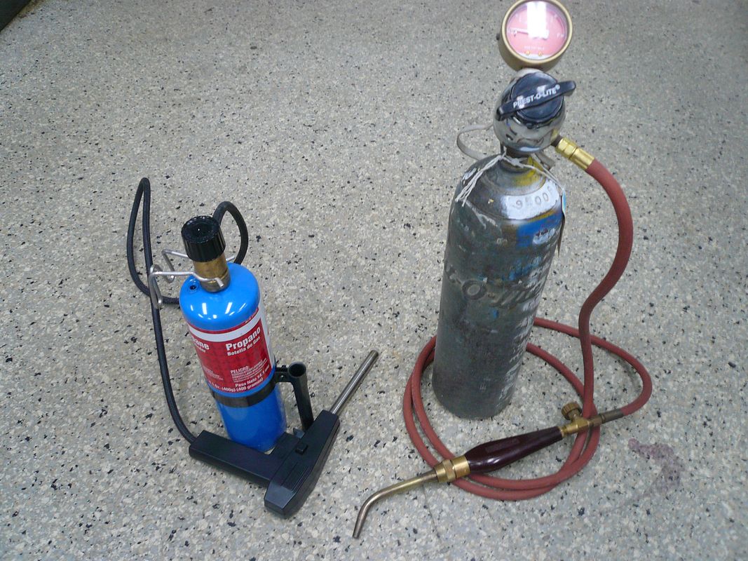
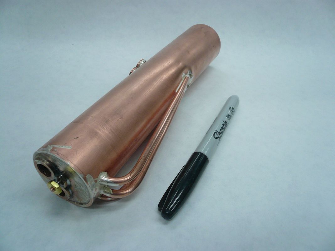
The boiler is fabricated from an 8 piece of 1 1/2 ID copper water pipe. The end caps are made from 3/32 copper sheet. The safety valve comes from Coles Power Models (
www.colespowermodels.com) and is their part number 29M3-2. It has a 5/16-27 MTP thread and pops off at 30 psi.
The 5/16-27 MTP is an unusual thread (at least in the US) and the tap is expensive, however, it turns out that, for this size only, a 1/16 NPT pipe thread is the same. The 1/16 NPT is somewhat standard and considerably cheaper. If youre not as anal as me and dont feel like you have to make every piece yourself, an even less expensive answer is to just buy pre-threaded bushings from Coles Power Models. Theyre about a $1.50 a piece.
I started by cutting the pipe to length and facing the edges.
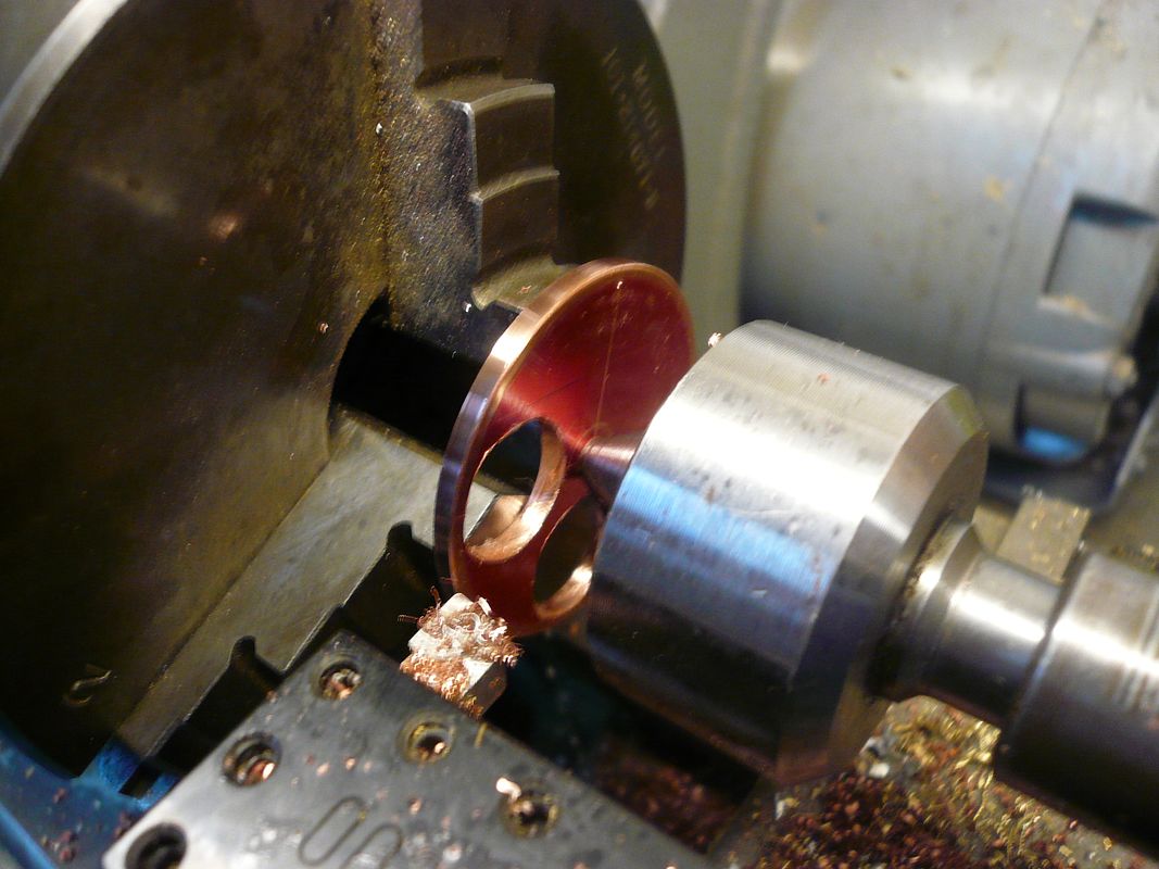
The boiler heads, or end caps, are made from 3/32 copper plate. I drilled the bushing holes before cutting the round because it was easier to hold. Copper is a bear to drill. After rough sawing the round, I took it to the lathe and faced the edges.
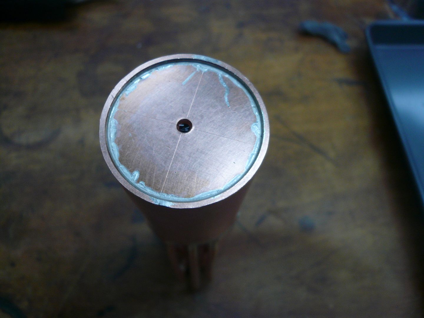
The live center applies enough pressure to the disk to hold it against the chuck jaws for turning. (A tip of the hat to Bogs for showing this in his flywheel post.) I forgot to mention earlier that theres an 1/8 longitudinal stay running through the boiler. Thats the stay hole the live center is in in the above photo. Also, its hard to see, but theres a slight chamfer on the edge of the cap. Thats to aid silver solder penetration. Silver solder doesnt like to flow over sharp edges. The cap is turned to a light press fit in the pipe.
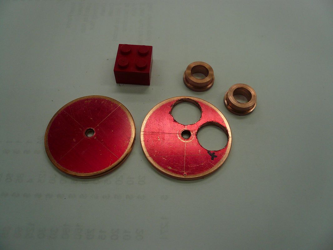
The bushings are turned from copper rod. I left them un-threaded because I couldnt come up with an easy way to hold them.
The above bushings are for the test valve and the pressure gauge. Bushings are also required for the safety valve and for the throttle valve.
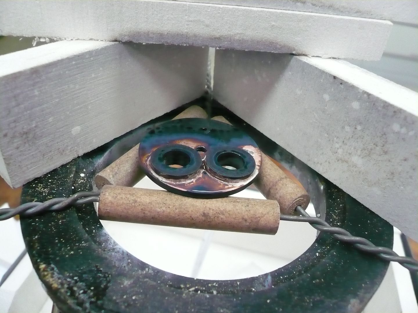
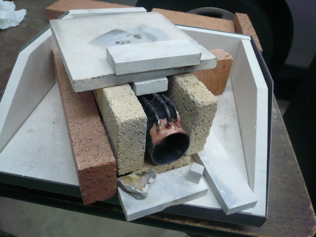
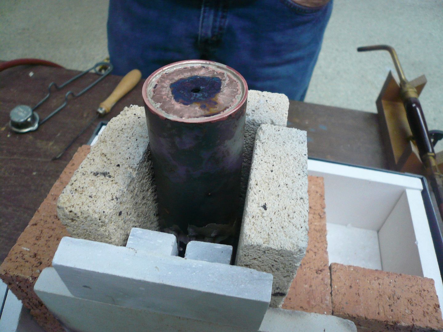
The end bushings were soldered with Medium solder.
I used medium because I didnt want to have to worry about the bushings unsoldering while I was soldering the cap in.
I should mention that Im doing the soldering in multiple heats. An experienced solderer could probably do multiple connections per heat, but I wanted to be able to check things out as I went.
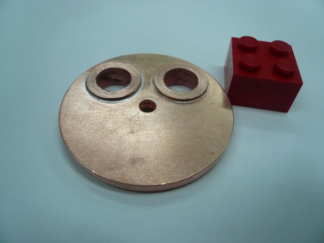
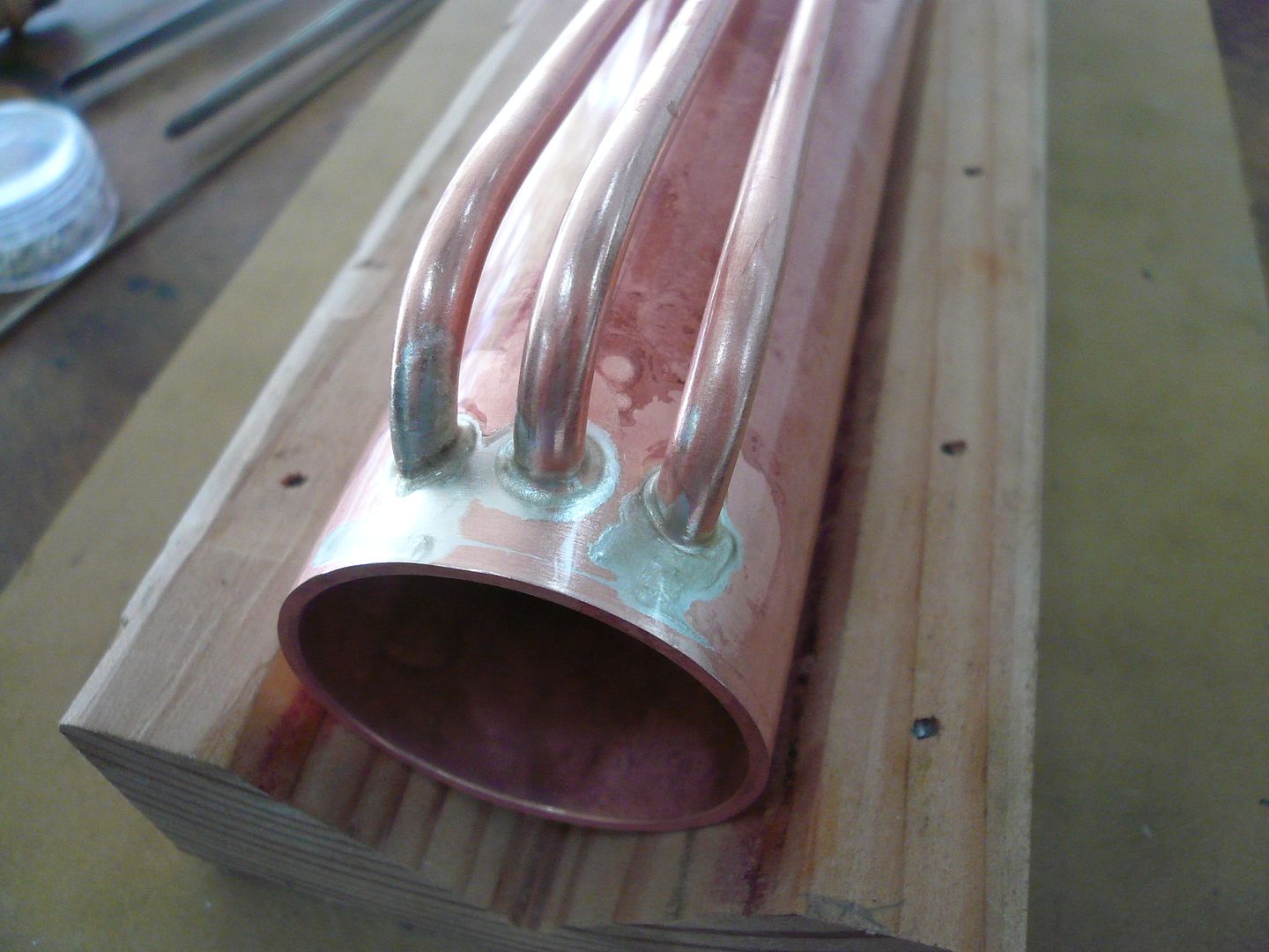
Anyway, the bushing joints turned out great and I was feeling pretty good.
However as we go along, youll see pride goeth before a fall.
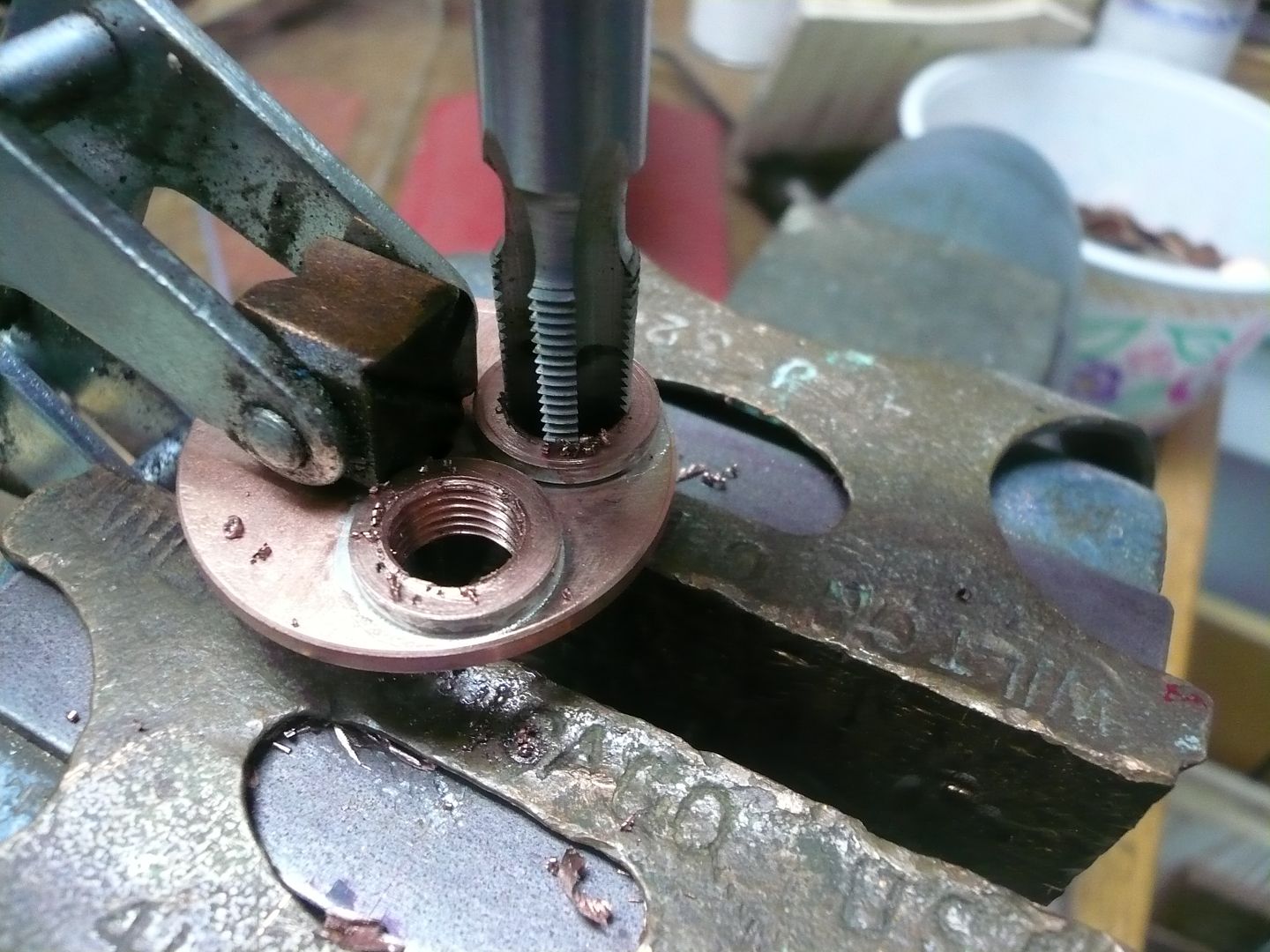
Next the bushings were tapped 1/8-27 NPT. Thats the head, held in a clamp, held in the vise.
Id never tapped tapered pipe threads before, so I had no idea how far in to run the tap. From looking on the web, it sounded like accepted practice is to run the tap in 12 threads or about three fourths of the tap length. If any of you can shed more light on this, please do. As it turns out, I could only get the tap in a little over half way anyway, but the fitting seems to go in okay.
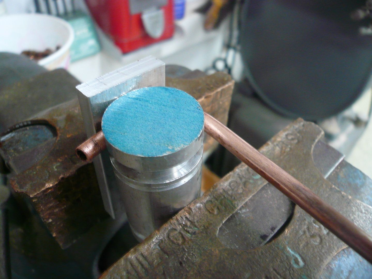
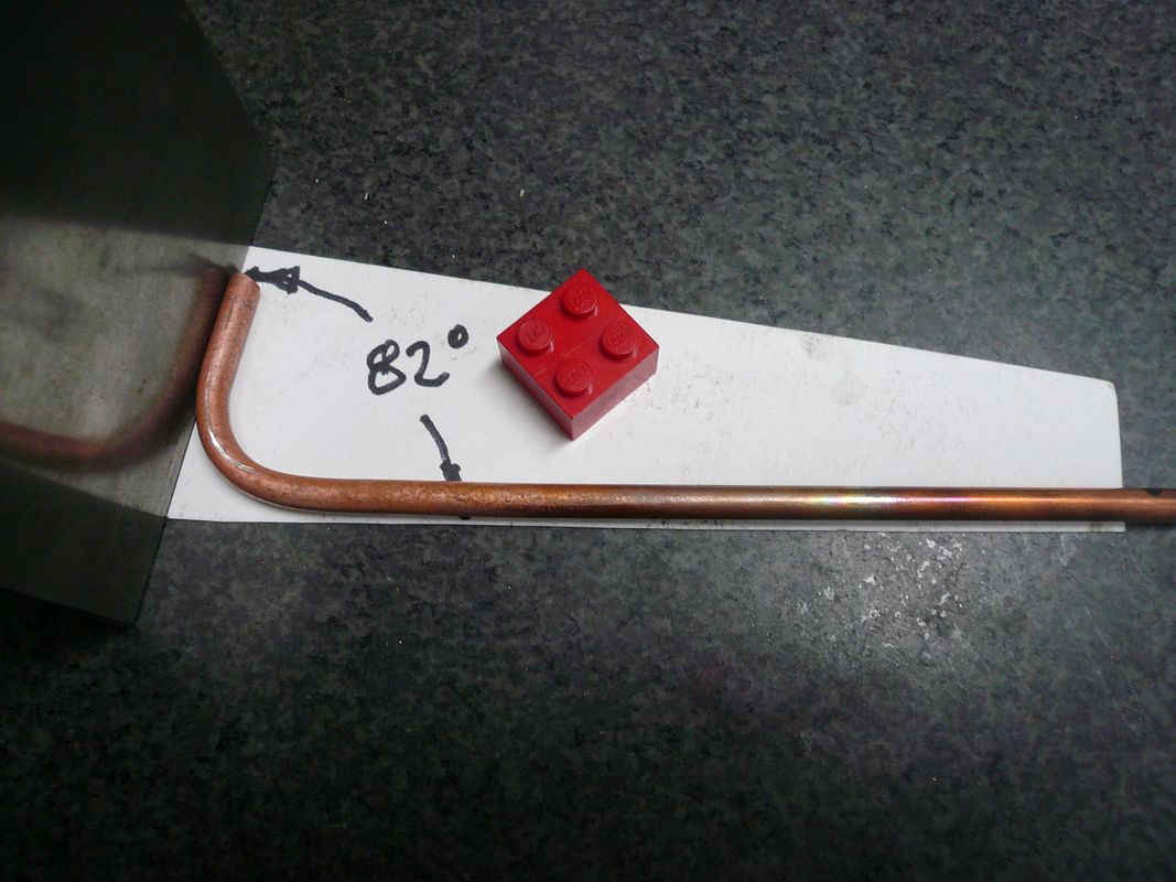
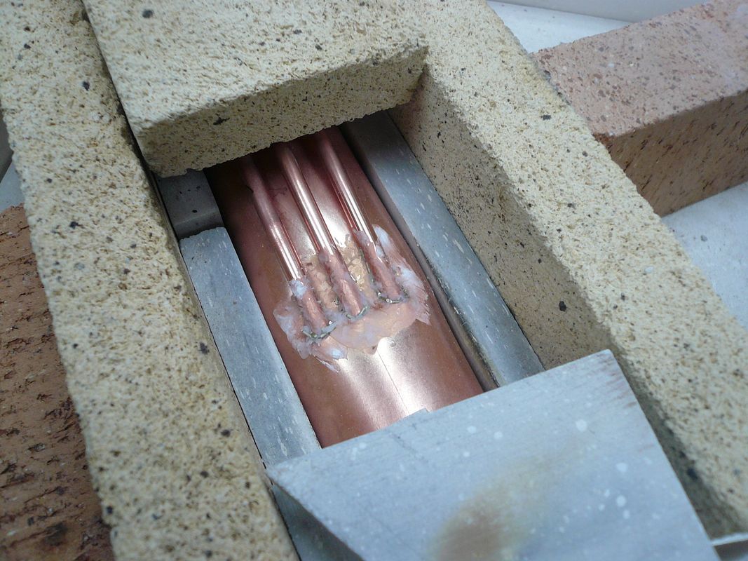
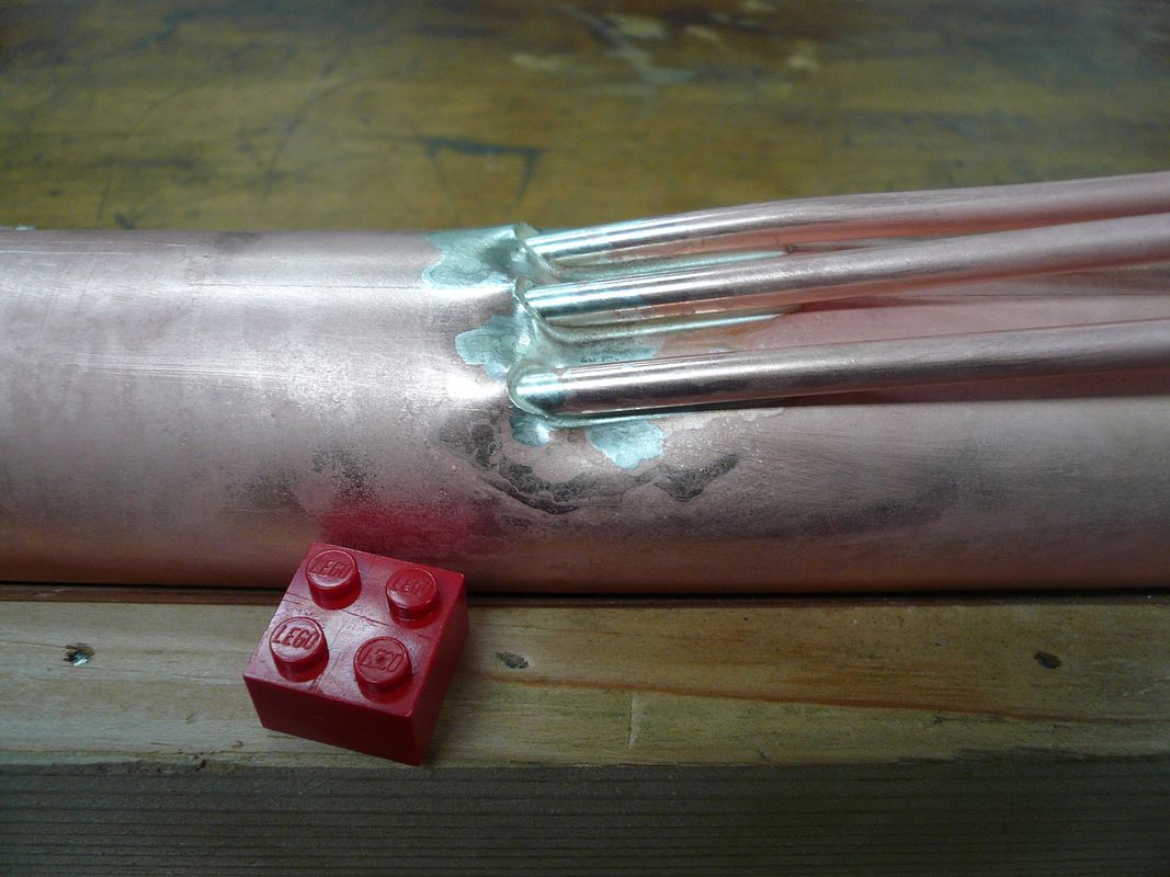
The boiler has three water tubes on the underside. These are formed from 3/16 copper tube. I formed them using a piece of aluminum with a 3/16 x 3/16 groove in it.
The aluminum is 1 OD, so the groove bottom is 5/8 OD. The groove keeps the tube from collapsing.
Make three tubes, all shaped the same. They'll be cut to final length when they're fitted to the boiler.
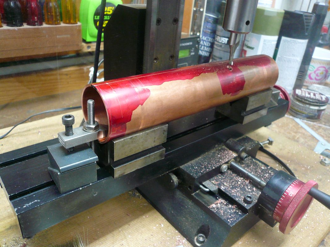
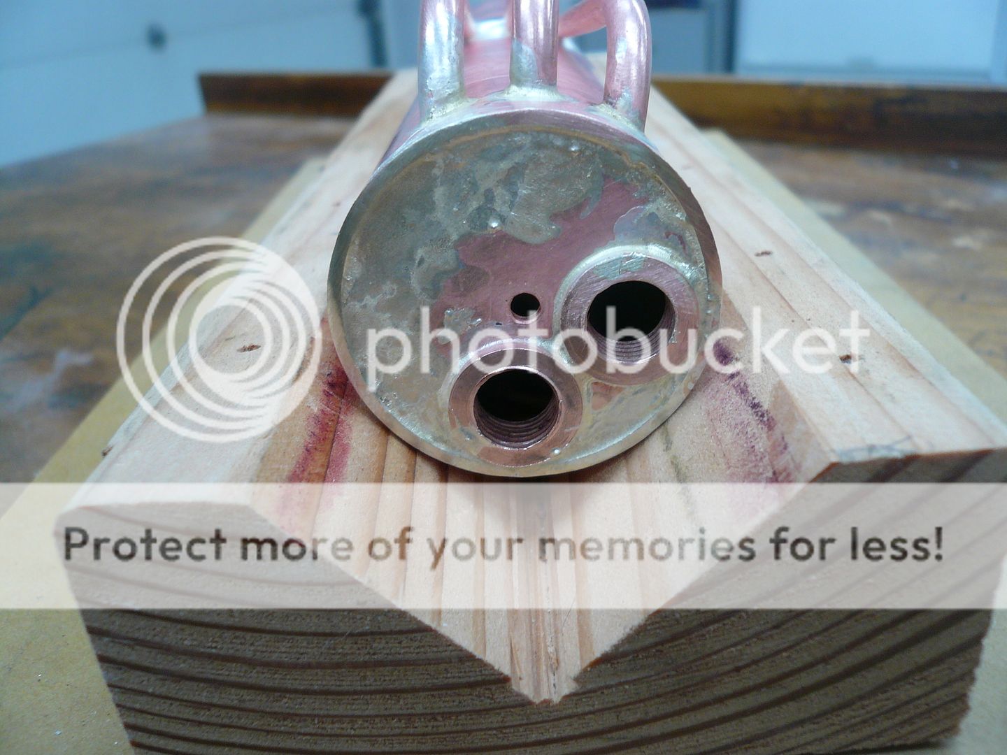
The six holes for the water tubes were drilled on the mill using a 3/16 end mill
I chose to do it on the mill, because the water tubes extend parallel to each other rather than radially. That requires drilling off the center line of the boiler which is almost impossible with a drill bit. The end mill holds its position better. (With this set-up, I also drilled the holes for the two bushings that go on the other of the boiler.)
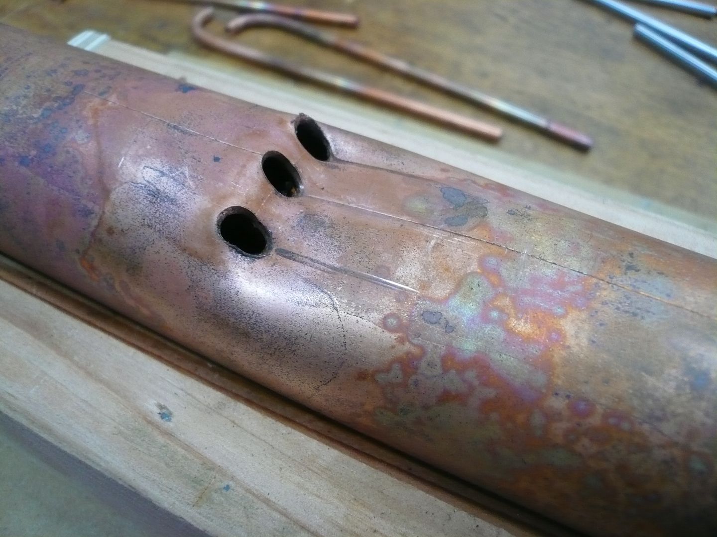
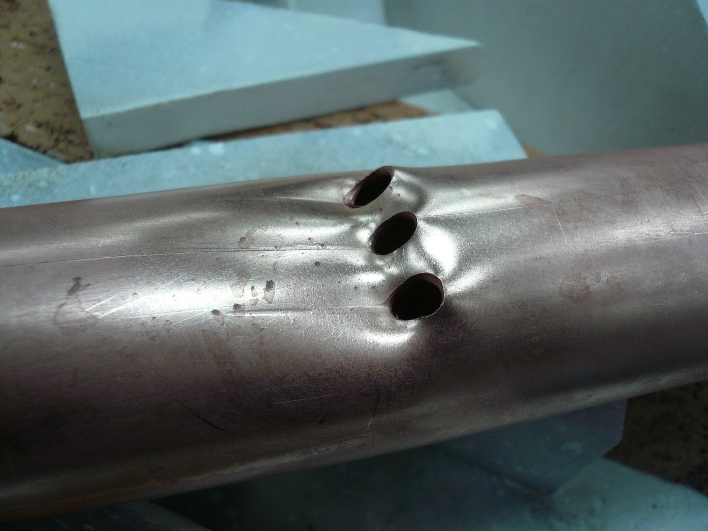
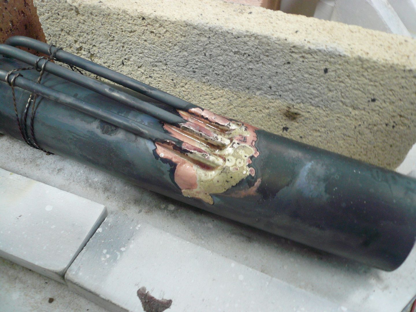
The water tubes enter the boiler at about a six degree angle, so the vertical holes had to be deformed to allow for this. First I annealed the boiler pipe. Then I inserted three pieces of 3/16 drill rod into the holes. The rods are vertical at this point (sorry, no photo). Then I pushed all three rods down at the same time to the required angle. Youll want to over bend slightly because the drill rods bend a little.
These are the resulting holes.
I need to stop here for now
more later.
Regards,
Dennis