Jerry,
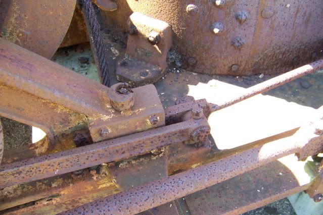
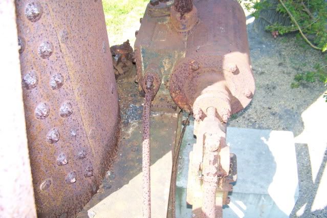
I would build it as shown in the photo.
Make a piece of flat with a boss to take the valve rod either screwed, silver soldered or welded into it. Then, dare I say it, BENT, to alignment.

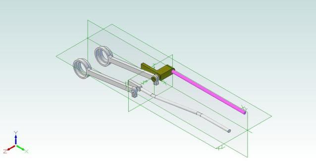
Reason - you have done such a great job of replicating and scaling the engine and your straight rod seems somehow not right. As my Grandfather would say, "Listen lad, don't spoil the job for a halfpenny of tar." :bow:
Remember free advise is sometimes worth exactly what you pay for it. :
Best Regards
Bob