Building Jerry's Donkey

Home Model Engine Machinist Forum

Help Support Home Model Engine Machinist Forum:

This site may earn a commission from merchant affiliate links, including eBay, Amazon, and others.
I made the crosshead guides today.

When I started this project, I considered all of the big pieces. If I had looked at all of the little pieces, I might have started on something else. The small parts aren't any harder, just harder. This is the cross head.

D10.jpg


Here are some pics of the successful (mostly) processes. My camera doesn't seem to get pictures of the disasters. I have a lot to learn and mistakes are one way to do that.

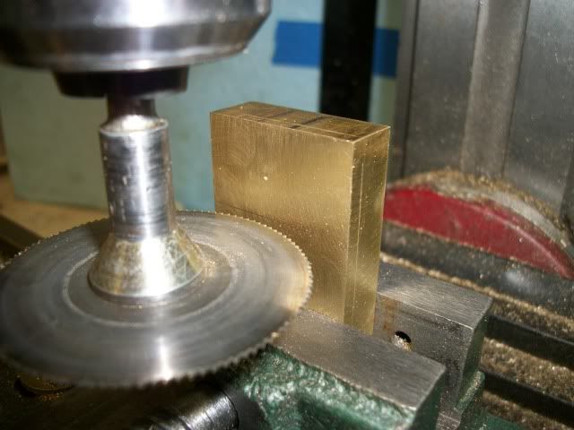
I started by sawing some chunks of brass to size:
Crossheads001.jpg


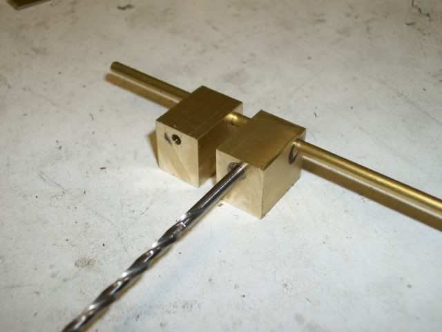
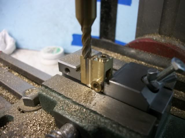
Drilled crosswise for the con rod pin and lengthwise for the piston rod:
Crossheads004.jpg


Once again, I'm using the tailstock ram and the live center to mash the part against a piece of oak against the 3-jaw chuck. I know, I look like a one trick pony, but its a good trick and it gets around my limited equipment. I don't have a 4-jaw for the lathe and this gives me a way to center the bore when it is not centered on the part.
part on lathe
Crossheads008.jpg


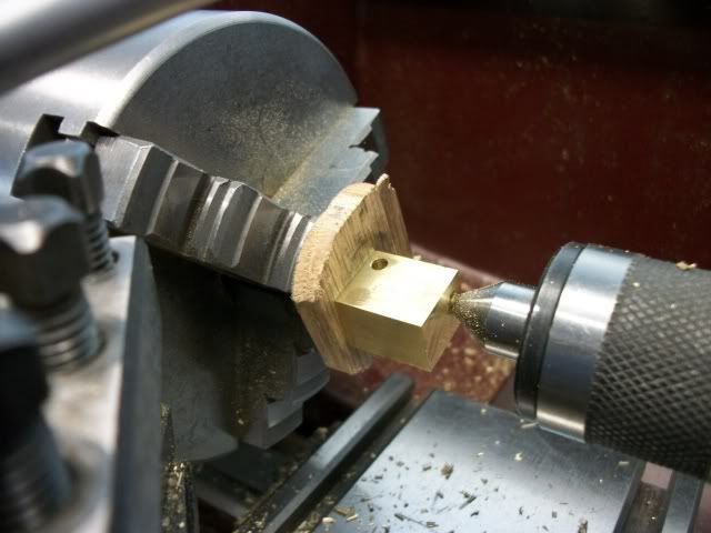
I modified the setup by adding a centering pin to maintain alignment. The part is longer than it is thick. Its not like a disk or a flat plate so this is important:
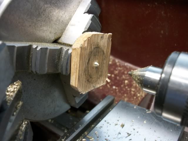
Crossheads007.jpg


The bosses turned:
Crossheads010.jpg


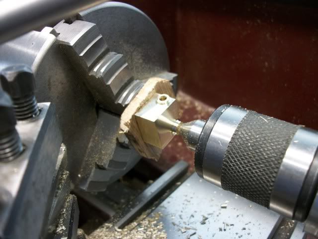
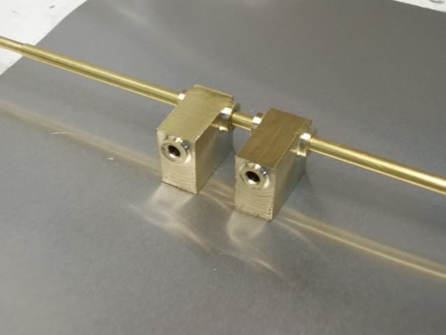
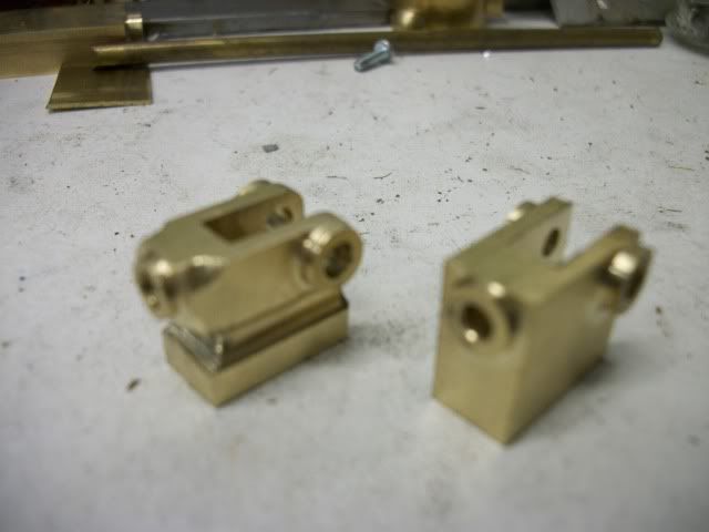
The piston rod boss was turned first and then one of the side bosses. When the part is reversed for the second side boss the first side boss sinks into the oak. Here is the pair complete with bosses:
Crossheads012.jpg


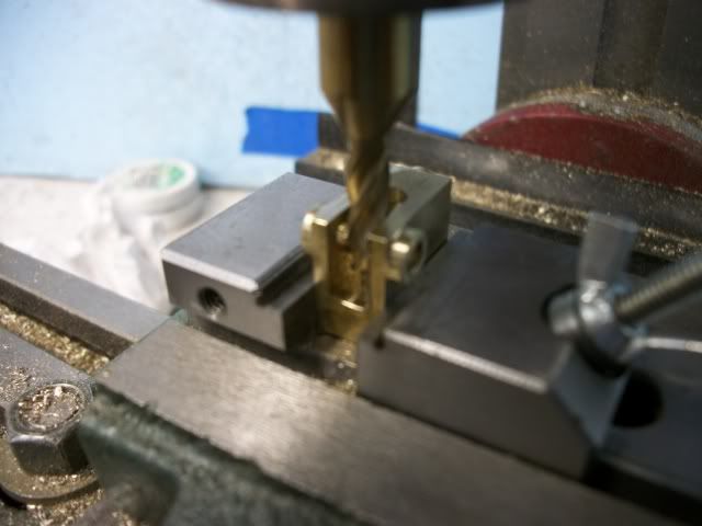
The slot for the connecting rod is milled:
Crossheads013.jpg


After a little profiling with an end mill and a little hand filling:
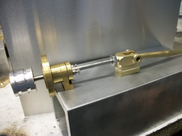
Crossheads018.jpg


Crossheads017.jpg


Trial assembly:
Crossheads019.jpg


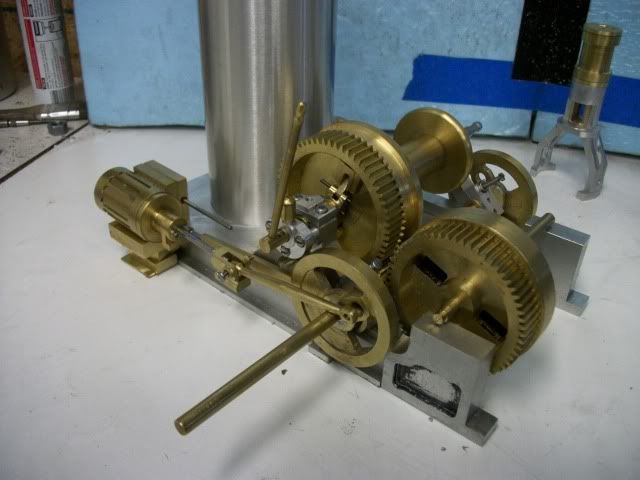
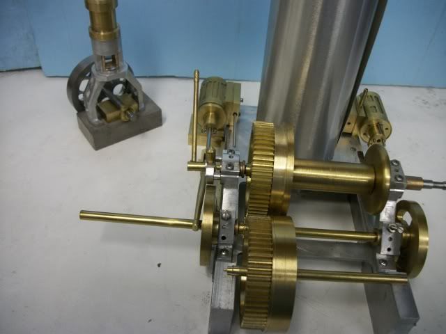
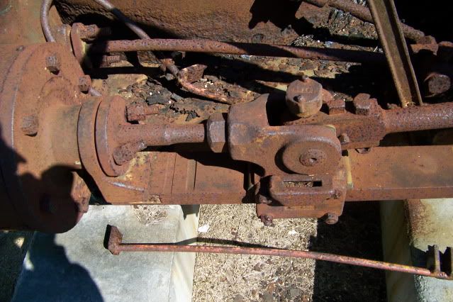
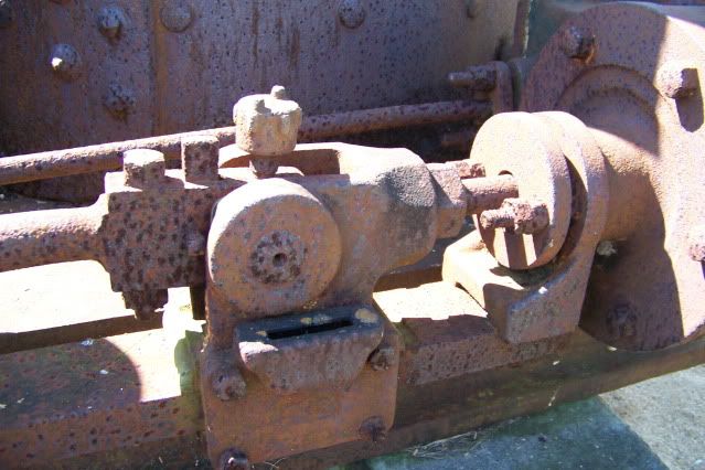
Thats it for the progress. Now a question for the experienced engineers. Referring to the first pic in this post, you will see two slots cut across the cross head guide between the crosshead and the piston. There is a similar slot across the guide at the far end of the stroke. These slots are probably to prevent a wear ridge from forming at the end of the stroke. But why two slots at the piston end? There is only one slot at the other end. Also not little evidence of wear on the bar. Based on obvious wear at other points, I would have expected to see more wear here.

Jerry

PS

When I started this post, I put some eggs on to boil for potato salad for the holiday weekend. Note: It took longer to write this post than it did for the pot to boil dry and for the eggs to explode!
 
I went back and looked at the picture of the crosshead guide bar and realized that those slots are way beyond the end of the stroke. The crosshead could not reach them so my first guess as to their purpose is wrong. So what are they?

jERRY
 
That's a headscratcher, Jerry. Those slots don't look like they do anything, but it's hard to imagine they
just put them there for fun. I don't know how this assembly was mounted or fastened down. Could
they have been for mounting brackets of some sort?

The guides look really nice!

Dean
 
Dean

The guide bar is suspended from the bracket on the packing gland at this end and from a plate that is bolted to the deck plate at the other end. It is attached by one bolt at each location, the bolt passes up through the bar into bracket, a screw really. It is difficult to make out from this photo because of the rust but the bracket is slightly wider than the guide bar and is notched to the width of the bar. The part number of the bar is "E204" and you can see the "4" sticking out from under the bracket. The rest of the part number is obscured because of the viewing angle.

My other thought was that the part might be used on other hoist and the notches were used to locate the bar but I believe that there was only one smaller machine in the series, so why 2 notches and the "E" prefix designates the "Eagle" model.

I used to know some people at American Hoist but they are all probably dead now and of no help.

Jerry

Jerry
 
Jerry,

SWAG............Oil retention grooves for pick up by a comb attached to the Xhead. They can be filled without getting the can munched by the Xhead. ??????????

Best Regards
Bob
 
Darn! Bob beat me to it! ;D

Bob's right....those are "oil cups" A piece of thin brass cut to look like a comb....which is what it's called attached to the crosshead....would dip into those "cups" and drag the oil across the cross head guide...every stroke....probably why you don't see any wear there....

You're doing a great job Jerry....I like the thinking on the setups..very creative way to deal with the situation......I would say your doing just fine....

If I can find a reference for a good comb design I'll send it along, but there were as many designs as grains of sand at the beach....I would take another good look at the prototype...there might be a remnant piece to look at.

Dave
 
Bob and Dave,

Thanks for the replies. Oil cups, maybe. But according to the brochure, lube is provided by an oil cup on the side of the crosshead visible in the photo. I dug up a pic of the other side where the cylinder is at TDC and the crosshead does reach the first groove so maybe my first thought (wear edge) is right, or a combination of both. This pic also shows the mounting of the guide bar a little better.

D342.jpg


Thanks for looking in,
Jerry
 
I'm enjoying this very much Jerry.
A very interesting project.
Any chance for a pic showing where you are? Some kind of "here's where I'm at"?
 
Captain Jerry said:
Oil cups, maybe. But according to the brochure, lube is provided by an oil cup on the side of the crosshead visible in the photo.

Jerry,

I agree about the oiler on the side of the X head but my understanding was that this provided oil to the underside of the guide and a comb was used on the upper side. However depending where the holes were drilled it could provide oil to both or one or the other.

Best Regards
Bob

 
Zee

Thanks for inquiring. At your request here is a picture of where I am with this project.

hoetieandShed004.jpg


Bob

I guess the side mounted oil reservoir could lube both top and bottom. Seems like all the rod deflection thrust would be down so the top bears the load. If the slot is an oil cup it still doesn't explain the second slot (closest to the cyl.) How long would oil last in those slots? I don't know what the crew for a rig like this would be but I doubt there was a full time Oiler. I would guess there would be an Operator, a Fireman, and a Line Handler or Tender with the Fireman doubling as Oiler. Most of the lube points are screw down grease cups which were probably daily. The Xhead and the piston rods look like the only regular oil points.

Jerry
 
Zee

After thinking about it for a minute or two, I realized that you may have wanted to see how the donkey was progressing so here is a current picture of the donkey:

hoetieandShed001.jpg


Jerry
 
Hi Jerry,

Often times....as I know too well, the engineer was the firemen was the oiler.... ::) ;D

I wouldn't have used grease on the cross head....attracts too much dirt...definitely oil there.

As to the final word on the subject...we may never know....but a path to the truth lies in the engine itself...who owned it?

What was it used for?.....Your local historical society may have a picture of her in use at some local industry......you'll never know till you look......

Dave
 
Captain Jerry said:
Zee

After thinking about it for a minute or two, I realized that you may have wanted to see how the donkey was progressing so here is a current picture of the donkey:

hoetieandShed001.jpg


Jerry


Rof} Rof} Rof} Rof} Rof} Rof} Rof} Rof}
Now I not only have cookies in my computer, I have cookie crumbs all over it.
Don't laugh with a mouthful of cookies.

Ron
 
Had enough of the smart ass?

Sorry. I didn't get to the shop today so these are pics from my archives. Seriously, I will try to get a progress update together on the donkey hoist and engine project in the next day or two.

Donkey Info:

Name: Hoetie. It makes more sense if you think "windmills" and say the full name out loud. "Donkey Hoetie"
My daughter has a wierd sense of humor and a literary bent.

Job: Companion. Horses are herd animals and don't like to be left alone, even when they are sick or injured.
Hoetie will keep them company with no antagonism, no running or playing. Just that sympathetic look.

Jerry
 
That's a fine looking donkey Jerry.

I wouldn't have guessed that was what you were building from all those parts you've made. Very creative. CNC?

:big:
 
Hi Y'all

Here is an update of the donkey. It actually looks like it is more complete than it is. A lot of the parts are in approximate position but not actually mounted.

donkeyupdate005.jpg

donkeyupdate006.jpg

donkeyupdate007.jpg

donkeyupdate008.jpg

donkeyupdate014.jpg


Progress has been fairly slow lately. I need to create a work plan and stick to it but it is easy to get distracted. There is a lot of design detail that still needs to be done. 3D modeling is deceiving. You can place a part and make it stay in position without really placing a bolt or a screw or a bracket to hold it there. When you actually get around to making the part, it becomes a whole design project of its own. It lots of fun but thankfully, I didn't submit a proposal that I have to make good on.

Jerry
 
Jerry,

What an impressive project.

When I try to hurry, it ends up taking me twice as long to finish.

If I slow down a little, I tend to get there faster.

Keep up the good work.

SAM
 
That is fantastic looking Jerry. Thanks for the pic.
I've been interested in this thread since you started it.
 
The assembly shot really shows off your efforts, Jerry. Looking great!

Dean
 
Looking Great Jerry!


......just one bite at a time.... ;D

You're doing just fine....just have fun with the challenges....

Dave
 

Latest posts

Back
Top