Building Jerry's Donkey

Home Model Engine Machinist Forum

Help Support Home Model Engine Machinist Forum:

This site may earn a commission from merchant affiliate links, including eBay, Amazon, and others.
Jerry,

I am enjoying your build.

The fluted lagging looks really good.

Thinking outside of the box is working well for you.

Regards,

SAM

 
Sam

Thanks for watching.

SAM in LA said:
Jerry,

I am enjoying your build.

The fluted lagging looks really good.

Thinking outside of the box is working well for you.

Thinking outside the box is necessary when the box is so small. This is my first ever attempt to model from reality and with no plans to follow some of the steps get pretty hairy.

I had to leave the shop today because the AC was loosing the battle with 100 degree outside so I'm trying to plan the next challenge. The front head has a long spigot with what looks like a hanging bracket. The bracket supports the cylinder end of the crosshead. The spigot also holds two studs that adjust the packing. It looks like it is cast and machined as a single piece! (not including the packing nut).

SteamDonkey004.jpg


I would like to make the bracket as a separate piece but I'm not sure it would be strong enough to support the crosshead. The two studs passing through it add to the strength problem. I guess I'll have a go at making it one piece.

Jerry
 
It turned out to be a lot easier than I thought. I didn't get any pics of the process but If anyone really wants to see how it was done, I'll be making the other one and I'll try to get pics. The only real problem is the tight clearances of the packing gland studs. The nut will clear the piston rod, but the corners of the hex hit the rod when turned. Rats!

PackingGland010.jpg


Jerry
 
Captain Jerry said:
It turned out to be a lot easier than I thought. I didn't get any pics of the process but If anyone really wants to see how it was done, I'll be making the other one and I'll try to get pics. The only real problem is the tight clearances of the packing gland studs. The nut will clear the piston rod, but the corners of the hex hit the rod when turned. Rats!

PackingGland010.jpg


Jerry


No Worries....make up some nuts to fit. The general rule is 1 1/2 times the bolt diameter.....eyeballametrically...it looks like it would clear if they were that size.

Dave
 
Jerry,

How about some socket head cap screws. They may give you the clearance that you need.

SAM
 
Dave,
Good idea, whittle some stainless down to 1/8" hex, :p drill and tap it 2-56, extract the broken tap, :mad: start over, get it tapped, cut it off, ZING!!! :hDe:, look for it on the bench, the floor, swarf bucket, start over, get it right!!! repeat 36 times. Pause.....thinking.....ZZZZZZZZZZZZZZ! Huh!! What!! No honey, I'm okay, just a small nightmare. :fan:

Sam,
In spite of the wrong appearance, my brain keeps nagging, "cap screws, yeah, that's the ticket". I've even thought about counter bored fillister head screws. Either one would be easier to adjust.

Kvom,
That's the answer. Damn the expense! I'll use them on the bearing caps as well.

The valve rod uses the same style gland. Only smaller. No problem, whittle some stock down to 3/32", drill and tap #0-80......... No honey! Nothings wrong, just another nightmare!!!

Jerry
 
Ouch. Kind of got your head bit off there, Dave...

Probably not worth mentioning that a pack of 25 scale SS #2-56 nuts is only $7. :hDe:
 
steamer said:
OK guess I won't bother doing that again...

Dave

My most humble apologies, I didn't mean to sound snappy. I forgot to put goofy little smiley faces all over the place to show I was joking. Some guys might be able to do that kind of work and not even think about it. I'm not one of those guys but I appreciate that you might think I am. In reality, I'm way over my head in this project, just scratching to keep it moving. Any indication that someone is watching helps tremendously.

Jerry
 
Awe that's alright Jerry. I would second American Model Engineering Supply in the sunny state of Florida.....Ask for Ron...as KVOM stated, he'll fix you up..

Damn fine man Ron is....good stuff, worth every penny. If your going to put the time into a model such as this....a few bucks for the jewelry is money well spent.

The best piece of advice I can give you....is slow down and enjoy the build.
I know there is some things to get accustomed to...small fasteners for one. Doing it infront of the audience isn't easy either. Scratch building from nothing is REALLY tough...ALL the engineering has to be done...either up front or in the mix....

Now, It's going well! its looking good, ........have fun with it too...and just keep eating that elephant...one bite at a time. You'll be fine.


I'll pull my other posts.....you add the funny faces.....deal? ;D

Dave

PS.... I mean it, that is really looking great....stick with it.


As promised, some pics of the gland/hanger. I don't throw away small bits of brass. This is the corner I cut off the square plate before turning the hoist gear blank. Next to it is the part hidden inside.

DonkeyGland001.jpg


DonkeyGland002.jpg


Probably not the way to hold it in the chuck. I recognize that it is putting a strain on the chuck but I was careful not to over tighten the chuck. Its brass, I'm taking very small cuts with a very sharp HSS tool bit. I'm working very close to the jaws so torque is reduced.

DonkeyGland005.jpg


When I am working this close to the chuck, I take steps to prevent a crash. With the compound set parallel with the ways, I run the compound to the limit of its travel toward the head. I then move the saddle up to the head and touch the chuck jaw with the cutting tool. I then back the saddle of just a few thou and lock the carriage. I use the compound travel to back the bit out beyond the end of the workpiece. All movement of the tool is with the crosslide or the compound and I can be sure that the tool will not be crashed into the jaws. This might be normal practice, I don't know. It's just how I do it.

A 1/2"OD spigot is turned and faced. It is then spot drilled, drilled through 13/64" ( the diameter of the gland nut ). Then a flat bottom hole was bored using a 3/8"dia end mill to match the depth of the spigot on the cyl head.

DonkeyGland007.jpg


Then over to the mill to shpe the lower support leg.

DonkeyGland015.jpg

DonkeyGland016.jpg


Now there are two.
PackingGland012.jpg
]

Jerry

 
You are doing some really nice work here Jerry. keep it coming.

To get back to the fasteners bit, and my personal view is that having the wrong fasteners on a model can really spoil it. I basically use three different types.

If it is a scale engine, as yours is, I will always try to use scale fasteners, either home made or bought. I will even modify bought in ones if needs be to get the 'look'.

If the engine is only semi scale, say like a lot of Elmer's ones, I try to keep the fasteners within the look of the engine, so I do make a few special nuts and bolts, but mainly scale.

If it is an engine that really resembles nothing, and came from inside my head, I use fasteners of any sort (except that I do hate Philips heads for final finish), as long as it looks neat, and I do try to hide most of the fastenings as well, if at all possible.

One thing I do do though is if buying in fasteners, it pays to do a good search around. I can usually get 100 normally for around the price you would pay for 10 or 20 from a model retailer. It does mean you have a lot in stock, but it also means that over the years, you can build up quite a collection and I usually have what I need at my fingertips, only needing to top up when they start to get low.

BTW, how to make acorn nuts is shown about half way down this post.

http://madmodder.net/index.php?topic=1054.msg9447#msg9447


John
 
Ok John spill the beans,where do you get fasteners at that price.
Don
 
Don,

If you can wait a bit, I was at Stew's this morning and he has found an even cheaper place, and he is sending me the link. I think he just paid less than 2 pounds or about 4 bucks for 2,000, yes that is right, 2K of 2mm nuts. He has also bought a load of cap screws as well. So until I get the link and have a good look about myself, I can't comment too much.


John
 
Cheers John,Sorry to hijack your post Jerry.
Don
 
don-tucker said:
Cheers John,Sorry to hijack your post Jerry.
Don

No problem Don.


steamer said:
Awe that's alright Jerry. I would second American Model Engineering Supply in the sunny state of Florida.....Ask for Ron...as KVOM stated, he'll fix you up..

Damn fine man Ron is....good stuff, worth every penny. If your going to put the time into a model such as this....a few bucks for the jewelry is money well spent.

Dave

I ordered scale nuts from American Model Engineering Supply yesterday. I ordered the 2-56 nuts and also a package of 0-80 which I will need for the valve rod gland. I talked to Ron a bit about the machinery that he uses to produce these little gems. It reinforced my feelings about doing it myself.

These things are not really all that expensive. Just a few pennies more than the standard stuff at the hardware store.

Jerry
 
Glad it worked out for you Jerry...

One of Ron's lubricators did yoeman service today on my steamlaunch
 
At last, some more progress on the donkey. I haven't been in the shop much lately. Lots of stuff going on around here and I keep losing my concentration. My grand daughter went back to college last week and she took my dog, Pearl, with her. Pearl is really Katie's dog but she couldn't go to school with her for Katie's freshman year, so she became mine for a while.

Damn dogs have a way of getting to you with their constant attention and complete approval. I'll miss her. I'll miss Katie too but I can talk to her on the phone.

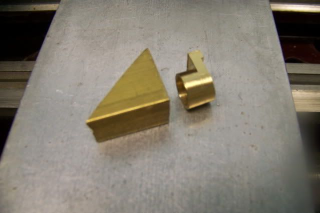
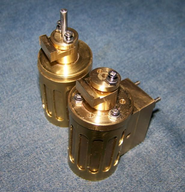
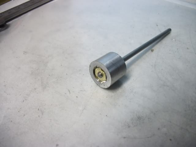
Today I made pistons. The piston rod is 1/8" stainless steel with 1/2" of #5-40 thread. The piston is .625" dia. and .5" long. I don't have any suitable aluminum rod so I decided to make them from a piece of 1/2" aluminum plate.

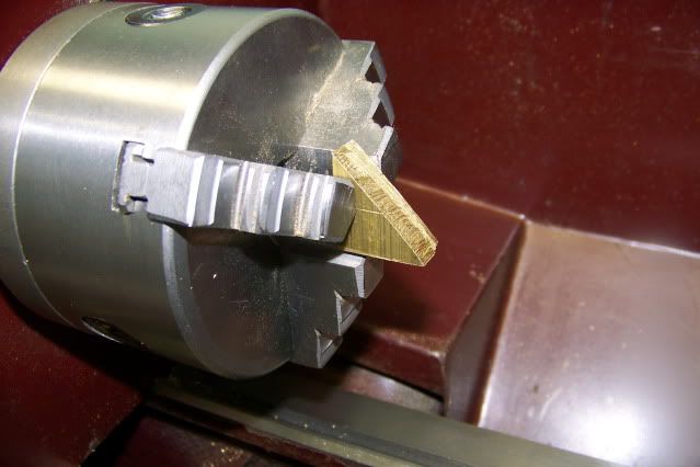
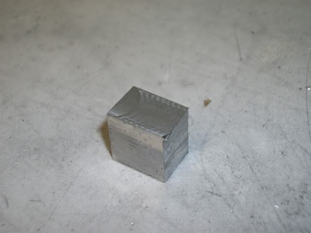
First pic is a little chunk of plate hacked of with a hacksaw:
Pistons003.jpg


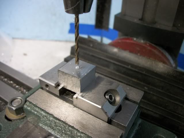
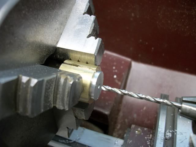
I drilled a little hole in the center for the live center:
Pistons008.jpg


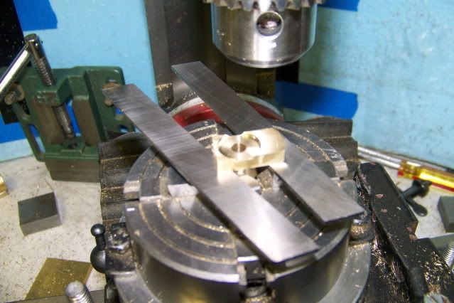
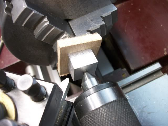
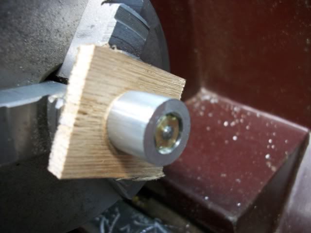
Then I mashed it up against the 3 jaw with a slice of 1/4" oak between the stock and the jaws:
Pistons010.jpg


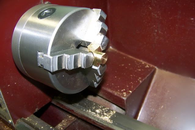
This is a slight modification of Bogs' plate flywheel method. The oak provides enough friction that I don't need to use any double faced tape, and I can cut the full length of the part and cut into the oak without damage to bit, part, or chuck:
Pistons012.jpg

Pistons013.jpg


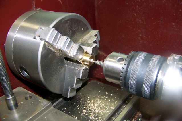
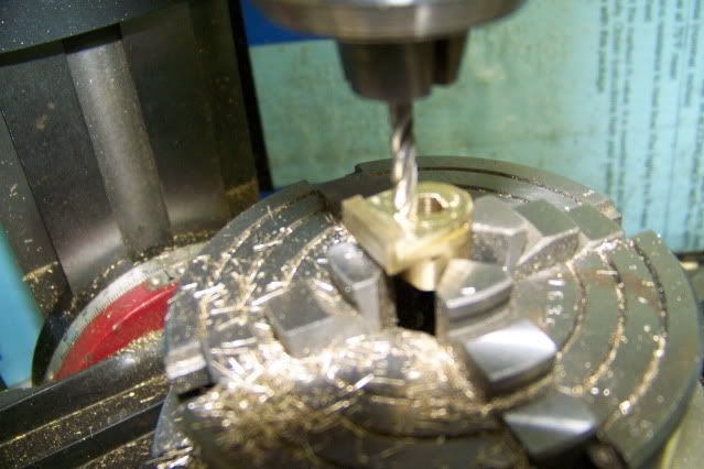
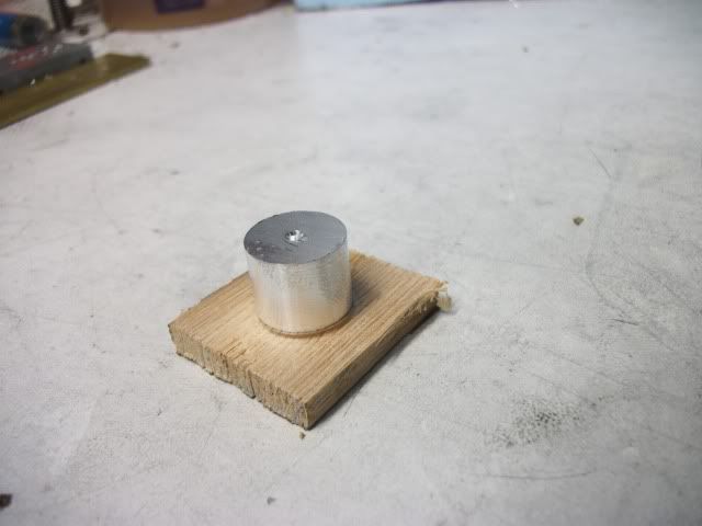
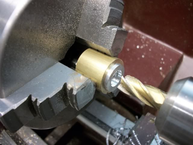
I left it slightly oversize so i can finish it concentric with the rod. Now that its round, I can mount it in a split collet and drill, counterbore, and tap it.
Pistons015.jpg

Pistons017.jpg

Pistons019.jpg


The counterbore is for the locknut. Its a close fit so if you look closely, you can see that two opposite sides of the nut have a small notch filed in them so they can be tightened with a two pin spanner.
Pistons020.jpg


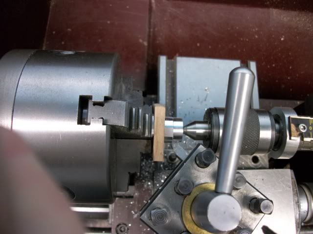
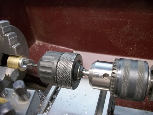
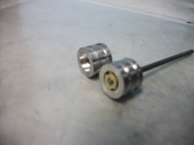
A 1/8" hole in the oak plate lets the assembled piston and rod be put back in the three jaw. I used the tailstock ram to press the piston and plate hard against the jaws before clamping down on the three jaw. The piston was then turned to size and grooves for packing added:
Pistons021.jpg


Pistons022.jpg


More to come. I think I've got the fire lit again.

Jerry

 
Back
Top