Building Jerry's Donkey

Home Model Engine Machinist Forum

Help Support Home Model Engine Machinist Forum:

This site may earn a commission from merchant affiliate links, including eBay, Amazon, and others.
Captain Jerry said:
The cylinder has a 6.25" bore and a 1" stroke in keeping to 1/10th scale.

I hope that is .625 Jerry ;D,shows I am paying attention anyway.
Don


This is truly a neat build. Learn something every time I look.

Ron
 

Bogstandard said:
The engine you are designing might do a little better if you make the bore somewhat smaller, 6.25" is a little on the large size. scratch.gif

John
don-tucker said:
I hope that is .625 Jerry ;D,shows I am paying attention anyway.

Don

Pesky little decimals. I'm sure that one moved after I posted. If you guys hadn't caught it, there's no telling where it might have gone.

Jerry
 
Gerry,

I wish the decimals in my bank balance would go the same way yours did. ::)

For compressed air I can't see any advantage in messing about with anything other than a bit of lead to give some cushioning at the end of each stroke.

Best Regards
Bob
 
Bob

Thanks for the suggestion. If I have this right, increasing the lead means that the steam valve starts to open before TDC and this is achieved by reducing the length of the valve slide. If I reduce this from .470" to .460" starts to open the steam valve at about 5 deg BTD but since this is an eccentric operated valve it only open slowly and slightly to ease the reciprocating motion of the piston at TDC. Is that enough?


Ron

Thanks for the link. I had seen the video on YouTube but not the Ebay listing. Interesting but I'm not bidding.

Jerry
 
Jerry,
Reducing the length of the valve with zero lap will give you negative lap.

The lead is altered by changing the angle of advance. This is done when the engine is timed so it will be easy to experment with different amounts, 5 degrees sounds like a good starting place.

Dan
 
Dan Rowe said:
Jerry,
Reducing the length of the valve with zero lap will give you negative lap.

The lead is altered by changing the angle of advance. This is done when the engine is timed so it will be easy to experment with different amounts, 5 degrees sounds like a good starting place.

Dan

Jerry,

What Dan said ;D This means you need some way to move the eccentric sheave from + 90 deg to +95 deg relative to each crank.

If the eccentric sheaves are set in their 90 deg position the other way around the problem is to add a bit, (say 1/64") of exhaust lap to the valves

Hope this helps

Best Regards
Bob
 
Dan and Bob

Direct quote from the AMHOIST Brochure:

"Eccentrics cannot slip nor be set wrong - they are an integral part of the crank web."

They make it sound like a good thing. There is no statement of the angle, (its not a technical document) so mine are set at 90 degrees. They could be changed but with some difficulty. I'm trying to get a good handle on all of the relationship in this slide valve mechanism so I have spent a great amount of time playing with Charles Dockstader's interactive Zuener Diagram

If I increase Lead by reducing the valve width, the steam valve opens before TDC but the opposite steam valve is still open. I guess that's negative steam lap (baaaad). On the other hand, I can reduce the valve cavity which provides the cushioning by closing the the closing the exhaust valve before TDC. I guess that's positive exhaust lap (gooood). That's what I will attempt to do.

Thanks for making me think about this a little deeper.

Jerry
 
Captain Jerry said:
If I increase Lead by reducing the valve width, the steam valve opens before TDC but the opposite steam valve is still open. I guess that's negative steam lap (baaaad). On the other hand, I can reduce the valve cavity which provides the cushioning by closing the the closing the exhaust valve before TDC. I guess that's positive exhaust lap (gooood). That's what I will attempt to do.

Jerry,
If the eccentric is fixed at 90 degrees which is proper for zero lap then the lead can not be changed as the angle of advance is fixed at zero degrees.

Negative lap is not good because at one point of valve travel both ends of the cylinder will be open to supply pressure.

I do not really see the need for lead with a small model engine as the reciprocating forces are small. Lead is needed on a large engine and on large vertical engines it was common to add more lead to the bottom cylinder end to counter the force of gravity.

I think your plan of exhaust lap is a good one. It was common to have zero steam lap on engines built for power like winches or ships steering engines.

My favorite valve diagram is the Bilgram diagram I find it much simpler to construct and visualize than A Zuener diagram.

Dan


Dan Rowe said:
If the eccentric is fixed at 90 degrees which is proper for zero lap then the lead can not be changed as the angle of advance is fixed at zero degrees.

Jerry,
That statement was not fully accurate as the lead can be changed with a fixed eccentric by changing the lap. However reducing the lap below zero is never done because admitting steam to both ends of the cylinder at the same time is so wrong.


Captain Jerry said:
I'm trying to get a good handle on all of the relationship in this slide valve mechanism so I have spent a great amount of time playing with Charles Dockstader's interactive Zuener Diagram

I would find Dockstader's Zuener diagram more usefull if the lap and the angle of advance were the slider variables and use the diagram to calculate lead and cutoff. The things you can change in a model are angle of advance and lap and valve travel so to me that makes more sense to make them the user input variables.

I had to try zero lap and lead on a Zuener diagram and the thing goes all flat line, the same thing will happen on a Bilgram diagram.

I really like valve gear discussions because they make me rethink the subject from a different direction.
Dan
 
Dan

Yeah, I agree that the Dockstader diagram seems a little wrongfooted but then It is a big help to me. Not so much the actual Zuener Diagram representation which I do not claim to fully comprehend. I get a better understanding of what is happening by moving the valve position slider and watching the valve edges. It would be even better if the valve position slider showed crank angle in degrees instead of valve position as a length dimension.

If I had thought to check out this stuff before building the crank webs and eccentric positions, I would probably set about 5 deg of advance angle.

Jerry
 
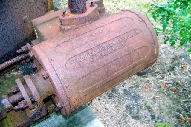
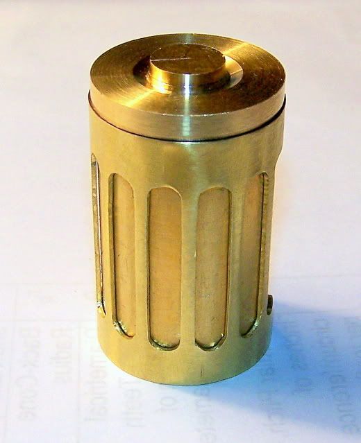
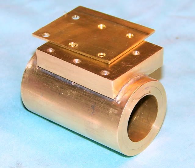
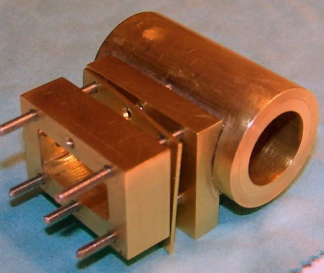
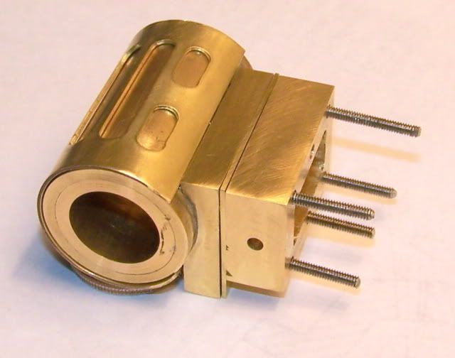
Today I got to work on the cylinders. This is what I am aiming for:

SteamDonkey004.jpg


The cylinders hang outside the frame. They are mounted by bolting the valve steam chest to the deck. The packing gland is not the normal threaded nut. The adjustable part (normally the nut) is a clamp adjusted by nuts on studs 180 deg apart.
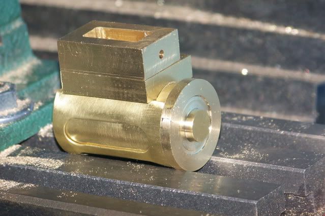
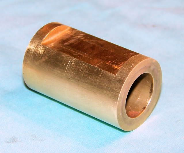
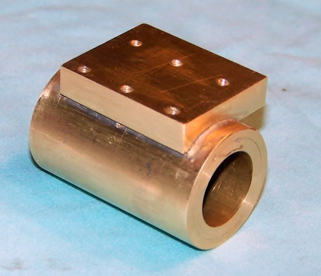
There is an extended neck on the cylinder head that supports a bracket that in turn supports one end of the cross head.

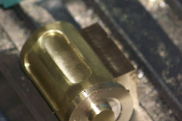
The most eye catching feature is the fluted lagging on the cylinder body. This has been a nagging concern since I started this project. I thought for a while that I would just ignore this little detail. There's no way I can do that, so I'll just make the cylinders plain and try to do something with paint. Then Cedge started show impossible stuff on his tandem engine build and that plan went out the window. Nothing replaced it. I still didn't know what I was going to do.

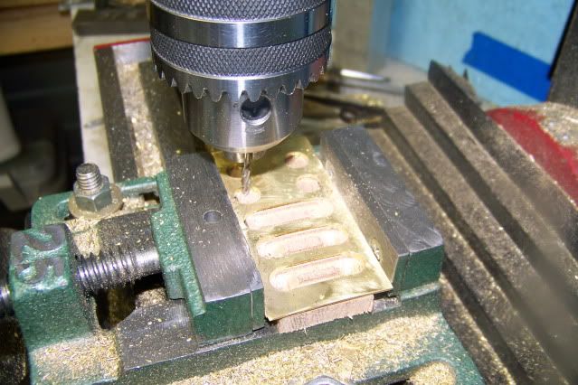
I was working on a valve plate and clamped down on the vise a little two hard and it bowed up in the middle. AHA!

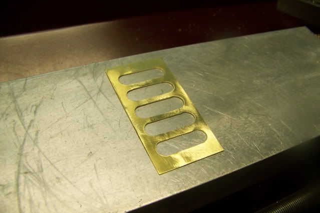
A little layout, a little drilling and milling:

DonkeyCylinder004.jpg


DonkeyCylinder005.jpg


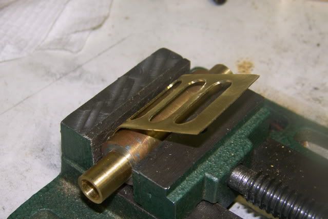
A little clamping and bending:

DonkeyCylinder006.jpg


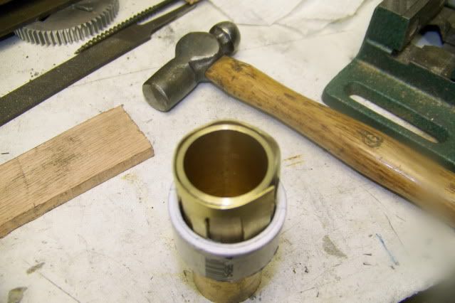
And I'm almost there. The problem is that with the cutouts the plate doesn't bend evenly. I tried lots of things but what finally worked was to turn a mandrel about 1/8th inch less than the cylinder body and bend the plate around that and then drive the assembly into a piece of PVC Pipe fitting. The next picture shows the plate inside the pipe and as you can see, it is not perfect, still has lots of sharp bends and flats.

DonkeyCylinder009.jpg


DonkeyCylinder008.jpg


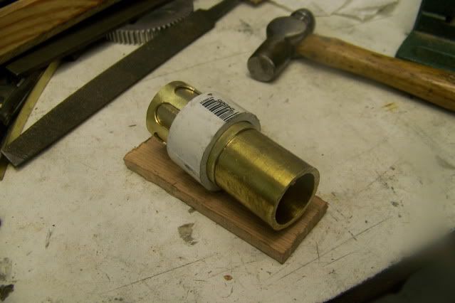
But, the PVC provides protection and form and the little hammer provides the persuasion and before long the plate is looking so good I forgot to take another picture in the fixture.

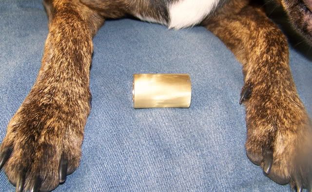
This is where I was when the thunderstorm hit and tree limbs and branches were bouncing off the shed so I grabbed the camera, called the dog, and headed for the barn.

DonkeyCylinder016.jpg


DonkeyCylinder017.jpg


It ended quickly with no real damage, but by that time It was beer and dogie play time so we called it quits for today. More tomorrow.

Jerry
 
That looks soo good, Jerry. You really have a head for figuring things out!

Dean
 
Dean and T70MkIII.

Thanks for waching. This was a real triumph for me. I got the method figured out but I was a little off on the proportions. I don't mind remaking a part if I can make it better and the cost is not too painful. Here is the revised part. The width of the flutes was reduced from .375" to .20" Much closer to the original.

DonkeyLagging007.jpg


Lot easier the second time around. I also learned that it is a lot easier to clean up the edges of the cutouts with a file BEFORE the piece is bent. Scrap cost less that $1.

Jerry
 
Thats a great job Jerry,I'm the same,if I am not happy with the finished job I will make another,learning from the first effort.
Don
 
I was not real sure how this part was going to work out so I kept putting it off. Somehow the cylinder and the valve chest have to get joined. Silver solder would be one way but its not the only way. I decided to use soft solder and screws. The main reason I chose this method is its reversible. If I screw something up, and that's very likely, I may be able to recover.

One of the reasons that I hesitated in this decision is that most of you will think it's lack of skill and nerves. I can live with that. HOWEVER...I don't think the integrity of the construction will be compromised. The project is intended to be run on compressed air so temperature is not a concern, but even if it were ever to be run on steam, the temperature will not reach the melting point of the solder. It might reach a temp that would reduce the strength of the joint but I am not relying on the solder to hold it together. After the plate is soldered to the cylinder, the holes for the studs are drilled and tapped into the cylinder. The studs penetrate through the plate an into the cylinder, stopping short of the bore. The solder is more like a gasket.

Here are some pictures. Those are not my hands in the first shot. My hands only look that way when there is a full moon. Those are the hands of my loyal assistant helping me to frame the shot.

101_5651.jpg


The cylinder has been milled flat to a depth of 1/8" to seat the plate.

101_5658.jpg


The plate is soldered, then drilled and tapped for the studs.

101_5659.jpg


The valve plate ...

101_5660.jpg


and then the valve chest are drilled to clear the #2 studs.

101_5661.jpg


Here it is with the lagging fitted.

101_5665.jpg


I didn't get to the valve cover or any of the steam passages but the sun will come up tomorrow, just like it did today.

Jerry

 
Back
Top