Back to Steam

Home Model Engine Machinist Forum

Help Support Home Model Engine Machinist Forum:

This site may earn a commission from merchant affiliate links, including eBay, Amazon, and others.
Jens,

Many thanks for the link to all four volumes. Lots of interesting reading there.

Colin

Colin

Nice to hear, but these books are mostly about control, regulation, etc. via camshaft, gear, lever etc .. :)
 
And now we have two!! The second stand turned out a bit nicer than the first one, mainly due to using a larger torch tip when soldering the joints. Although my solder joints on the second piece I built were quite lumpy, I also had enough build up of solder that when I machined/filed/sanded away the solder I didn't want, I had very few "craters" left below the finished surface. These two stands were probably the most difficult pieces to build. I'm looking forward to machining the aluminum base in the coming week so that I have something to mount these two pieces on.
CkLf5j.jpg
 
Hello Brian

I have lurked for some time on this forum and now you have gone and inspired me to get busy with this engine.

I have done the easy engines that most of us have started learning with and been successful with getting a runner eventually. I am going to follow along with your build as I have most of the material already for it.

Wish me luck!

Frank
 
The base for this engine is going to be Ahhhh---Interesting. Nothing horribly complex, just a lot of milling and drilling. I am going to make a simple jig to hold the soldered "towers" in the correct position and mark thru with a transfer punch to establish the 8 tapped holes which hold the towers in place. I find it a bit strange that the pillow block bushings for the crankshaft are mounted 'upside down' to what I consider normal practice. I still have not fully recover from the sciatica pain in my lower back, but at least I feel improved enough today to do a bit of CAD work. I was supposed to be working in my office on the other side of town today, but I phoned over and begged off for today.
tM4EIO.jpg

ythFkN.jpg
 
This afternoon I have been well enough to dick around with 3D cad, but too sick to machine anything or go to my real job across town. The base for this engine, as originally designed had a lot of machining on it, 80% of which was purely cosmetic. Same for the crankshaft bearings. I have endeavoured to get rid of any machining which was not absolutely necessary for the function of the engine, and it makes for a tremendous difference in the amount of work. The changes shown here will not effect the operation of the engine in any way.
VvlRXI.jpg

z8GEqW.jpg

0DMIHA.jpg
 
I have yet to tackle a steam engine with a reversing gear. I'm looking forward to see how you make that part.

Thanks,

...Ved.
 
Ordinarily, I don't use transfer punches, instead depending on my DRO's to match all the holes in different parts that have to bolt together. However, in this case I deemed it necessary, for a number of reasons. The 5/8" diameter rods you see sticking out of the top of the brass assemblies (which have reamed 5/8" thru holes) are also fitted into 5/8" reamed holes in the aluminum baseplate. I used a machinists square to align the brass assemblies "square" to the side of the aluminum baseplate, then used a transfer punch to mark thru to the baseplate. I will now put a small, discrete "match mark" on each brass assembly and on it's corresponding home position relative to the base so I don't mix them up later. There is about 0.030" clearance between the top flanges of the brass assemblies. I have a ton of machining to do on the base now, and I know that the brass assemblies will go back together with the base the way I intend them to. Each of the transfer marks will be tapped #5-40 in the base for the bolts which hold the brass assemblies in place.
7YI7V8.jpg
 
YOWZAHH!!! We have the two built up brass cross-head guides mounted to a base. There is a lot of work in that base, but I like the way it turned out. I can't get over how small this thing is. I'm not sure what part I will build next, but probably the bearings and crankshaft are the most logical.
8VYOJ1.jpg
 
Way back at the beginning of this thread, I said that it appeared as if some of the engines dimensions looked like they might be straight conversions from metric to Imperial. Not so--it's just that they built this thing with a 9/32" diameter crankshaft. That is a really unusual size.--A quick check of my reamers shows that I do indeed have a 9/32" (0.281") straight flute reamer, but----I don't have an undersize reamer to use for making a built up crankshaft. However, all is not lost. I do have a 5/16" (0.3125") diameter reamer and an 0.3110" reamer for press fits. So--I'm going to bump the crankshaft up from 9/32" diameter to a full 5/16" (0.3125"). I have checked and there is enough room on the bearings and the connecting rods to bump the bosses up by 1/32" to accommodate the larger crankshaft diameter.
 
Here I am carving the outboard crankshaft bearings out of some aluminum bronze. Either my endmills are all duller than a hoe, or else this stuff is harder than the devil's horn.
JfxYrS.jpg
 
I'm sure that if 100 engineers/machinists were asked "How do you turn that round bit on either side of the rectangular bearings?" you would probably get 100 different answers that all work. This is what works for me. I machine the bearing blocks to finished size on the outside, put the appropriate bolt holes in, and ream the bore to 1/32" undersize. Then I turn up a short piece of round bar that is a snug fit in the bearing block, coat the round rod with Loctite 638 and assemble as you see them. For the two outside bearings which have 1/16" oil holes in one side, I drilled 1/16" thru the bearing and thru the round rod so that I can Loctite a short piece of 1/16" crs rod thru both bearing and shaft because the cuts taken in the lathe will be interrupted cuts and I wanted the extra insurance that the bearing wouldn't break free from the round rod while I was turning them. The center bearing has an oil hole also, but when I made the two halves I drilled a clearance hole on one half and a #5 threaded hole in the other half, so it will put enough "squeeze" on the stubby shaft that I'm not concerned about it breaking free from the shaft while turning it.
lq0NG5.jpg
 
So, very carefully the bushings are turned on their stub mandrels and fitted to the aluminum base. The bushings are all currently reamed to 0.281" during this first operation. A bit of experimenting shows that a 0.281" reamer will pass thru all three bushings after they are installed in the base without wanting to take any large amount of bronze of any of the three bushings, which is very encouraging. The next stunt is to take my 0.311" reamer and take a complete pass thru all of the bushings with it, watching very closely to make sure that the reamer is not being pulled "out of position" by any radically "out of alignment" holes. This seemed to go very well, so now I move up to the final size 0.3125" reamer and slowly run it thru all three bushings. Now for the big test---does a 0.3125" shaft fit thru all three bushings? This is not guaranteed, because if any one bushing was too far out of alignment, the reamer would be quite happy to follow the out of alignment hole. Reamers will not straighten or "true up" a misaligned hole. They are more flexible than you would ever believe. Luck was with me!! A 5/16" shaft does fit thru all three bushings.--a bit reluctantly, but only a bit, and it can be turned when in place. Before I go any farther with things now, I will mount the base to my work-bench, put an 8" v-pulley on the shaft, and after a liberal application of oil I will drive the shaft for an hour with my old half horsepower bale elevator motor. this will take any "stickiness" out of the bushings and should let a shaft rotate very freely, which is what I am aiming for.
y8Ef1K.jpg

c9IupM.jpg
 
Here we are "running in" the new bronze bushings. I bought that motor from a farmer for $10 about 10 years ago for a replacement motor on my big power hacksaw. Turned out it was only a stuck brush on the big hacksaw motor, so I have kept my red 1/2 HP motor for a "spare". The 8" pulley originally had a 3/4" bore, but I have made up a collection of split bushings so I can run it on 1/4", 5/16", 3/8", and 1/2" shafts. The pulley on the 1750 rpm motor is a 2" diameter, so the crankshaft is turning at about 440 rpm, which seems to be about right for running in bushings. Any faster and it burns them and they end up too sloppy, any slower and it takes too long to get the job done.
HibAwD.jpg
 
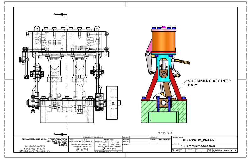
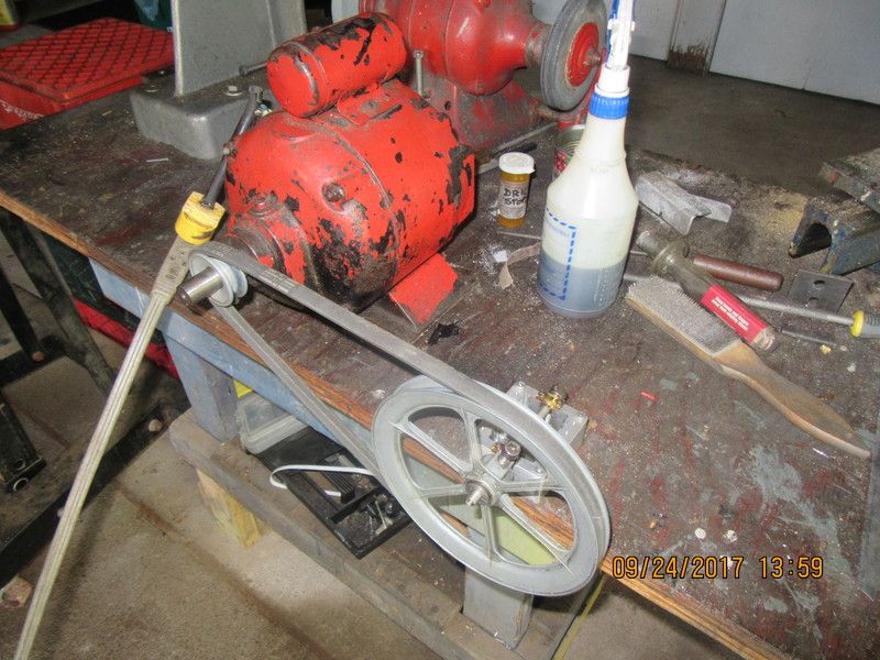
After the motor ran for half an hour the crankshaft bushings were much looser---but not loose enough. These little steam engines really don't like any resistance in the crankshaft bushings at all.---So--I switched out the short piece of 5/16" shaft with the pulley on it for a piece about 12" long, coated it with 600 grit carborundum paste, and using the pulley somewhat like a steering wheel I pushed the shaft thru all 3 bushings with a twisting in and out motion for a couple of minutes, making sure at all times that the shaft was engaged with all 3 bushings. (It wouldn't do much good if it was just a rotating movement--that would give annular grooves around the inside of the bushing.) Pushing the shaft in and out and turning it at the same time very quickly cut a couple of tenths off the inside of the bushings. After cleaning up everything in a varsol bath and blowing thru the bushings with compressed air, I reassembled the short shaft with a bit of lubricating oil, and it spins very freely.
 

Latest posts

Back
Top