90 degree V-twin engine

Home Model Engine Machinist Forum

Help Support Home Model Engine Machinist Forum:

This site may earn a commission from merchant affiliate links, including eBay, Amazon, and others.
When I look at pictures of your finished parts, I catch myself
looking for tool marks. Every machining operation leaves tool marks.
With your attention to detail they are often very hard to find.

Rick..
I thought I was the only one doing that. I'm at a total loss for adequate superlatives over this project.... and I know lots of big words...LOL. I can truthfully say that I come on the board looking to see if George has posted new photos.

Steve
 

Nice machining job on those fins, your choice of depth of cut for those fins is very well thought out, it gives a nice balance to the rest of the part.

Very nice attention to detail, as you filed the fins to give a nice smooth corners, that takes good filing skills.

As well as the sheen you were able to get on the rockeers them selves. very nice round over on the edges.

Verry good choice of sizes of the individual components, everything put together has very nice proportion to the overall part.

I like how you took the time to do rotary table work on the individual pieces, that encourages me to take the extra time and set up my RT. to get that extra detail, I would like it to have.

All in all good progress on your build.... :)
 
It's been awhile since my last update. I started on the cylinders, got through roughing the O.D.'s and started drilling and boring when my Logan started acting up. I've had the lathe about 12 years and bought it from the original owners wife. On several occasions it would start, hum and trip my breaker so I had it looked at. The repairman said it was in good condition and could find nothing really wrong so I put it back together which is no mean feat in itself. Over the years it would do the same thing once in awhile. I found that by cycling the switch (rotary) several times it would go away. Well this latest occurrence could not be overcome so I took it to another motor shop. The fellow there said that the starter switch was jammed so he bent the tab allowing it to open with the governor. I paid my money, took it home, reinstalled it, fired it up and starting making chips. That lasted for 2 days, and then back to the same old shenanigans. I called up the motor guy and he said there were no parts available for it and he didn't know what to do. After a short conversation of how it didn't even last a week he said bring it back and he would look at it again. I'm getting pretty good at lugging that brute out from under the lathe cabinet so back it went for 3 more days. Long story short, he could find nothing wrong and in fact he couldn't get it repeat the problem. I picked it up installed it again for the umpteenth time and so far it's working.
Now that you've heard my motor story I'll get on with the cylinder build.
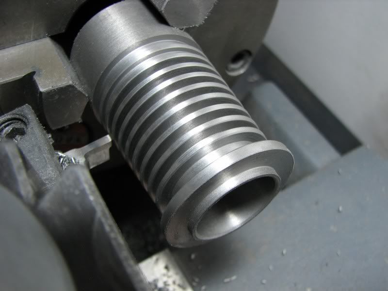
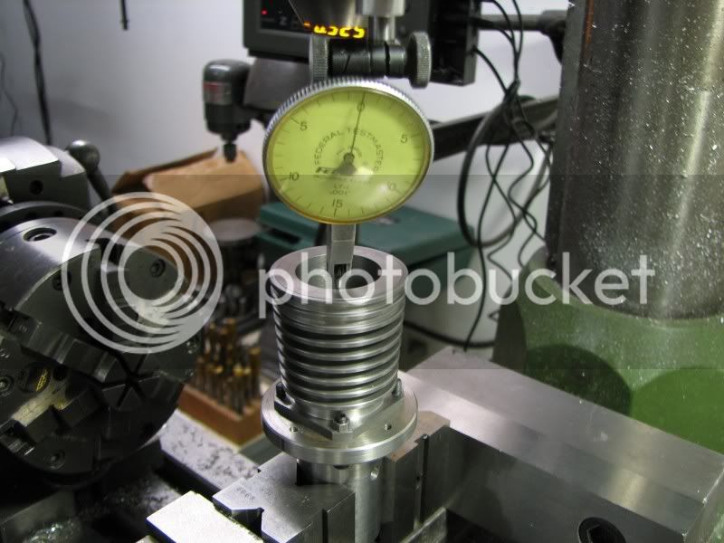
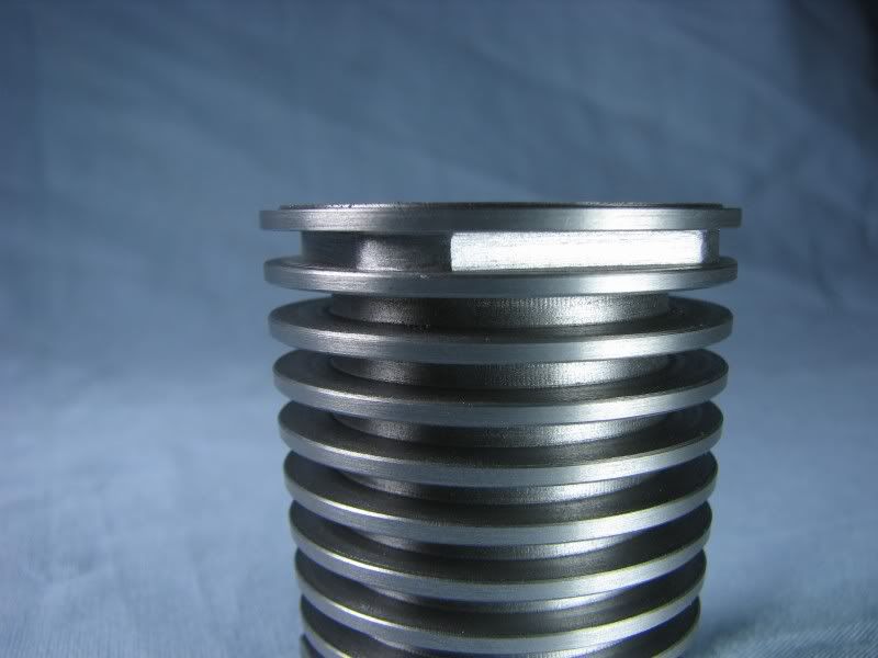
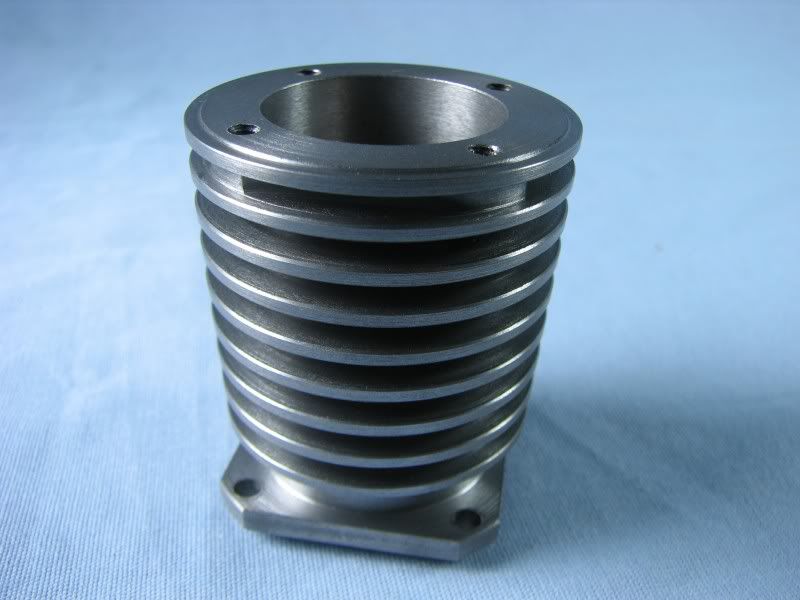
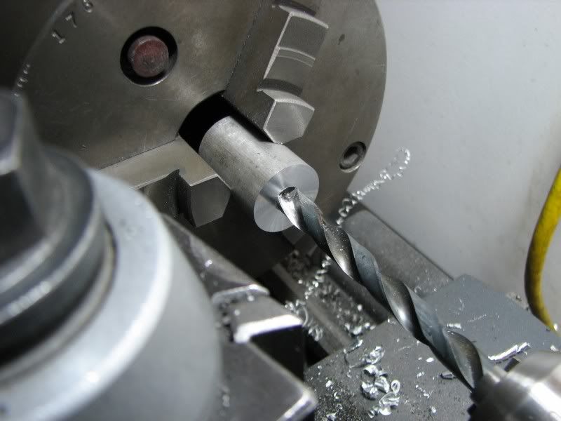
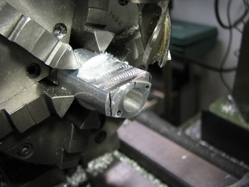
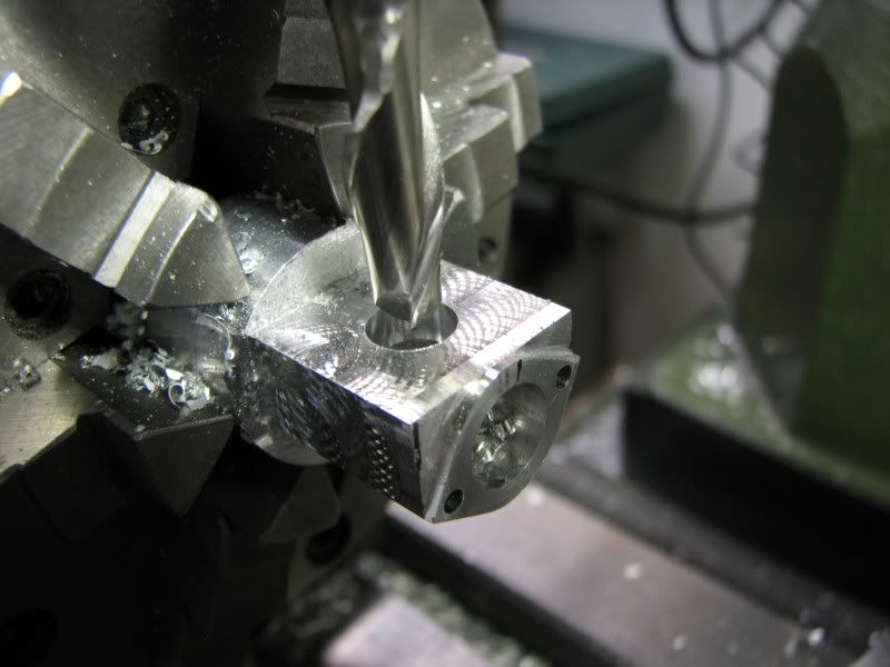
The cylinders are made from Durabar, a continuously cast iron having very fine grain structure. I didn't have a large boring bar so I took a piece of .625 drill rod and made one up. Nothing fancy just 3 inches of full diameter and 2 flats milled on the other end to fit in my QC holder. I drilled the cutting end .25 and drilled and tapped a hole from the bottom to hold a round piece of carbide from a broken end mill in place. Although I have used high speed necking tools to do fins in the past they have always been in aluminum and I didn't want to stop and sharpen the high speed to keep a good edge on it while cutting the iron. I looked into buying a carbide tipped cutoff tool but it was rather pricey so necessity being you know what I took one of my brazed carbide tools, milled the stock out from under the carbide leaving a .09 blade and then ground the carbide down to .096 wide. I must say I had a little doubt as to it holding up but it did both cylinders with no problem.
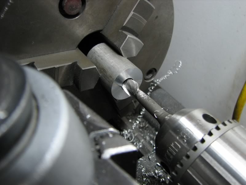
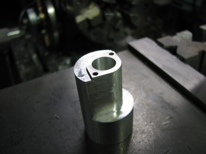
The first picture is the tool and the fins on the cylinder. I didn't show the turning or boring as it was a straight forward operation.
KV.jpg


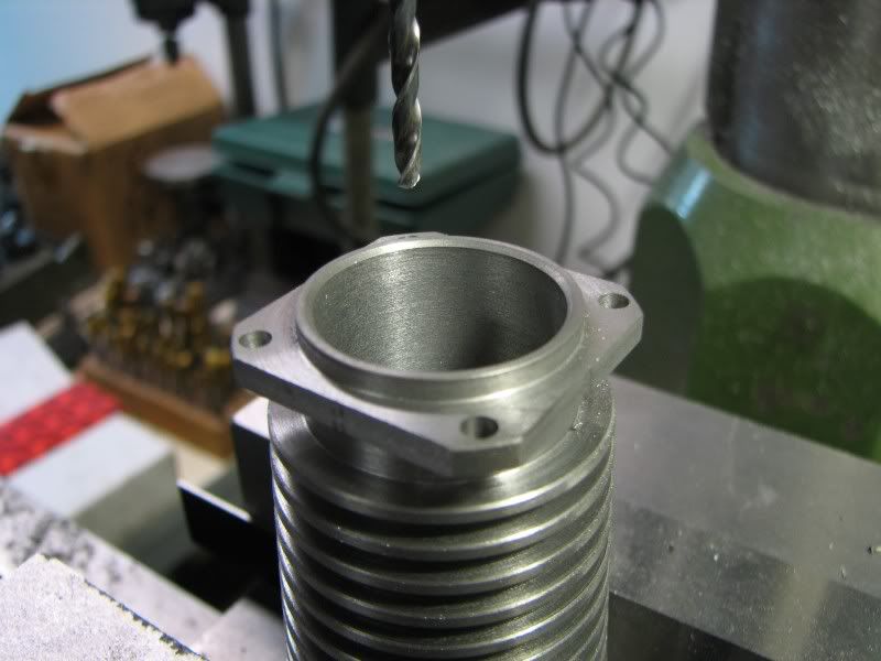
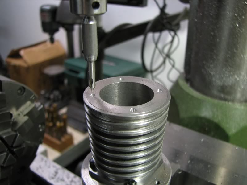
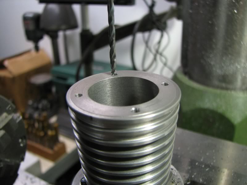
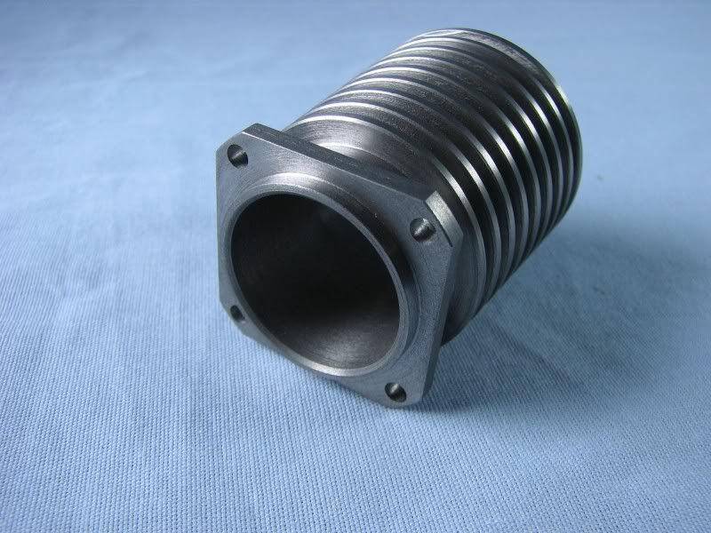
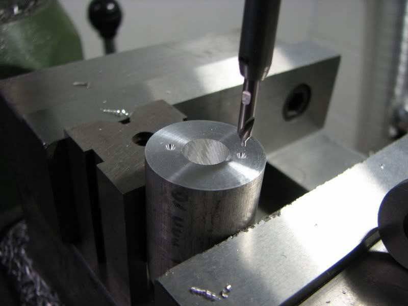
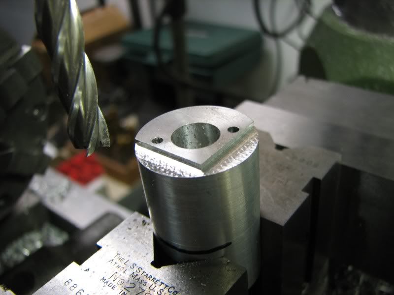
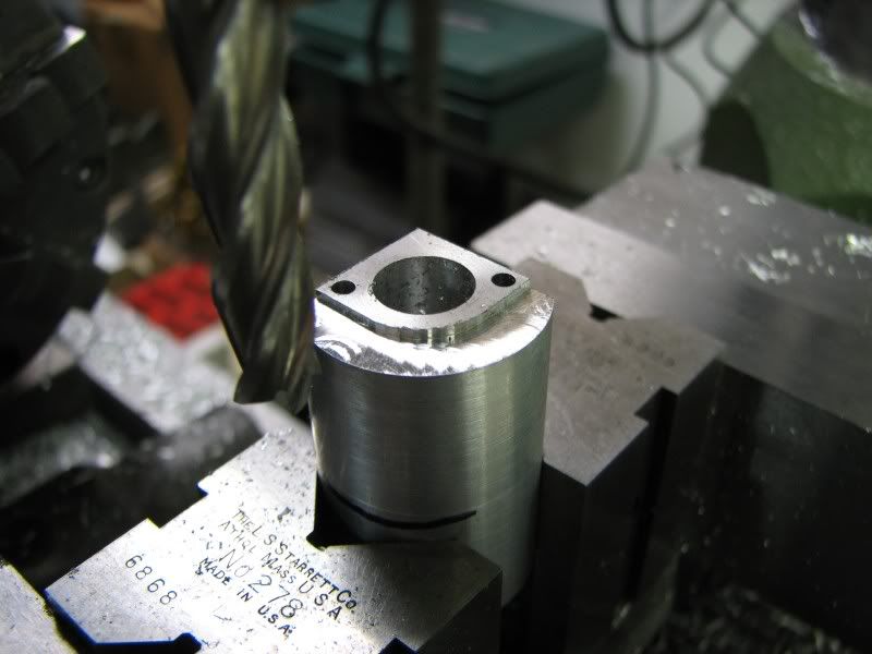
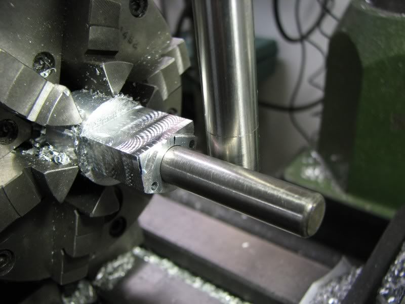
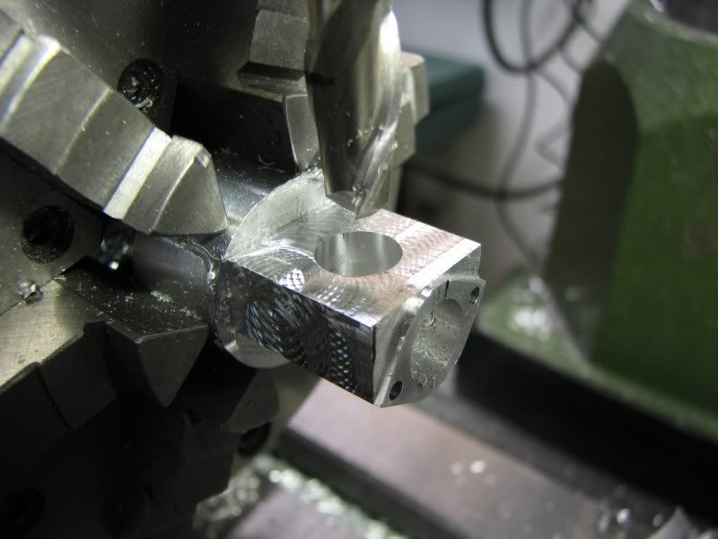
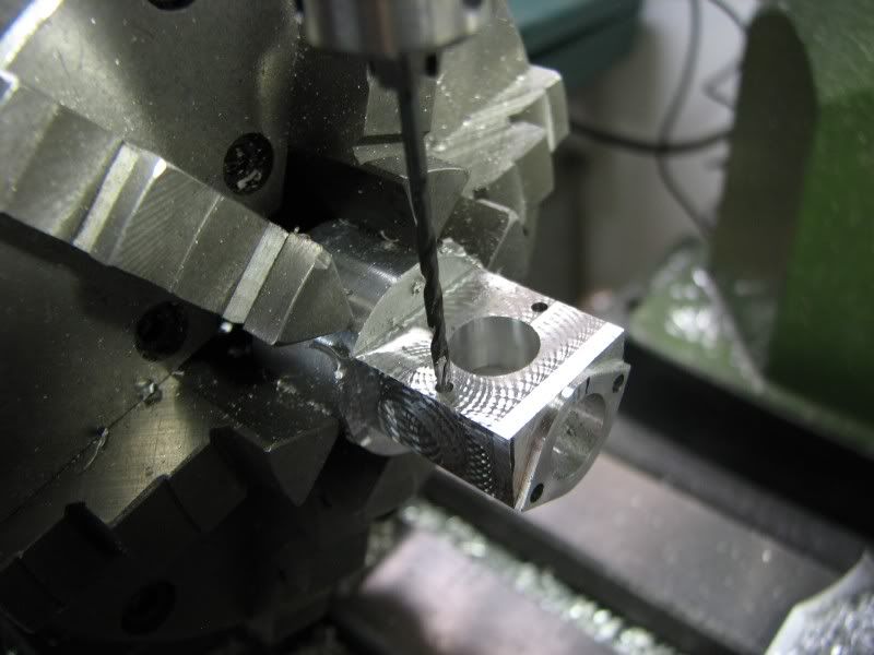
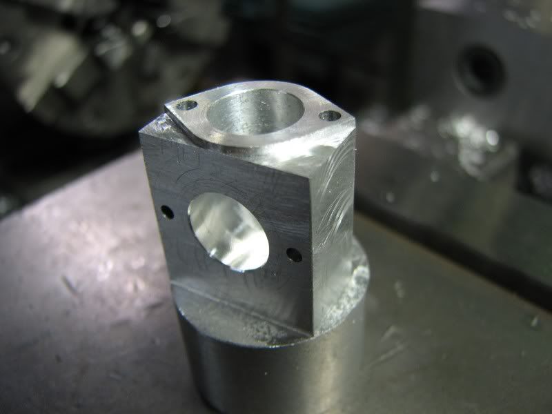
From the lathe I put the cylinder with it's chucking lug into the mill and drilled the mounting holes. While it was set up square to do the holes I milled the mounting flange square.
KW.jpg


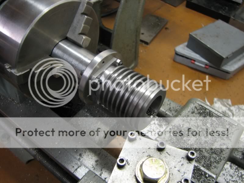
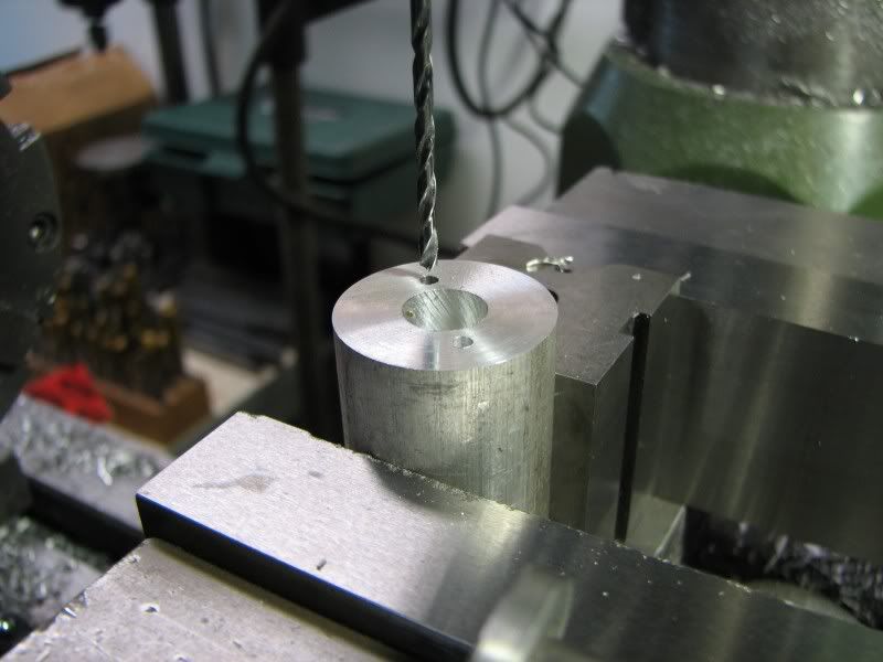
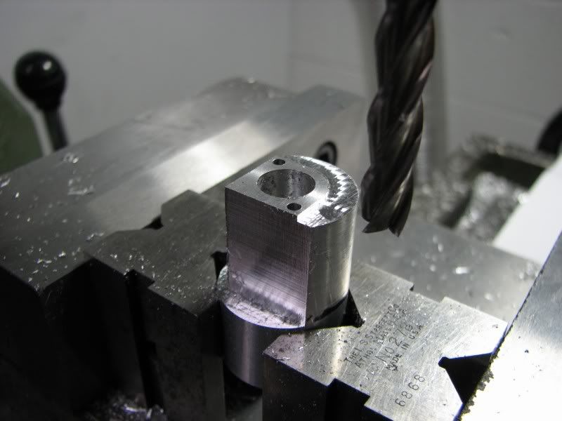
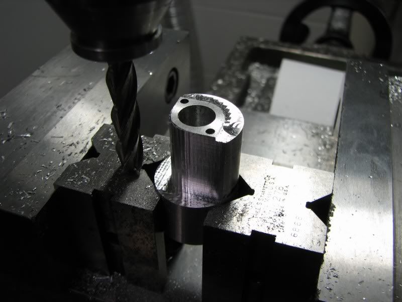
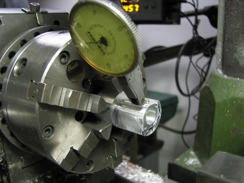
From the mill I took the cylinder out to my vertical bandsaw and cut the cylinder off of the chucking lug. This was at the time when my big lathe was down and I know my small lathe would have groaned at that task. I had a mandrel from my Holt build so all I had to do was drill and tap corresponding holes to mount the cylinder. I mounted the cylinder and faced it to length in my 6" Atlas lathe.
KX.jpg


Now the whole affair, cylinder and mandrel went back to the mill. I clamped the mandrel between two small v blocks to make sure it was secure. I indicated the lower flange to make sure it was parallel then indicated the bore so that I could put the head mounting holes in (5-40).
LB.jpg

KY.jpg

KZ.jpg
LA.jpg
 
With the drilling complete I mounted the same mill saw that I used for the cylinder heads and relieved the excess metal from between the upper two fins. I wanted to leave stock where the head bolts are so that's the reason for this operation.
LD.jpg


Here are two more pictures of a finished cylinder.
LE.jpg

LF.jpg
 
The final three pictures are, one with the head mounted to the cylinder and two with the cylinder sitting on the crankcase. As the parts get made I just have to fit them together to see what it looks like. All that's left to do on the cylinders is a little sanding and honing the bores out.
George
LH.jpg

LJ.jpg
 
WOW, I really like the look and style of your V-Twin George.

I continue to look forward to your future progress :) :) :)

Jeff
 
It's a stunner, George. Besides all the quality workmanship, which would be impressive on any type engine, your design has a very pleasing line. The contrast between cylinders and heads looks great, too.

Thanks for outlining how you made your parting/fining tool for us.

Dean
 
That is a fine looking engine. Excellent. Always a lot of 'wows' in your threads.
 
Outstanding work there, I cant wait to watch the video of it running.

Tim
 
Wow George.
Takes a man of real skill and patience, to achieve such an amazing
piece of art. If only i had a quarter of your talent i would be very
happy man. I look forward to seeing more. :bow: :bow: :bow:
Ken
 
Amazing workmanship George :bow:

Regards, Arnold
 
Thanks everyone for your gracious comments. With the big lathe back in operation I turned up the flywheel yesterday. Nothing out of the ordinary, just a disc type, 3.00 diameter, .86 wide with a .50 bore and a recess cut out of one side to lighten it up a little. I have to run over to my buddies shop to broach the keyway into it. I have a .062 and a .125 broach but not a .094. I have to order some 7075 aluminum for the pistons so my next update will be delayed a little. I just have the pistons and pins to make and everything can be fitted and put together. The only remaining parts are the intake and exhaust manifolds. I was wondering what to do with the intake manifold as it has to be fabricated because of the bends in it. My original thought was to make it out of brass and silver solder it but really didn't want to go that way because everything else was aluminum. Along the way I remembered that my son and I had been to a motorcycle show and one of the vendors was demonstrating how to weld aluminum with a bernzomotic or small propane torch. At first I thought it was a gimmick but as he demonstrated it and had me weld a couple of pieces I thought, "this is amazing". I say that because I have a TIG welding outfit that uses Argon gas for shielding and I can weld aluminum with it. I thought why on earth do I have to use my sophisticated welding outfit when I can weld with a small gas torch. In my poking around on the internet I have found that there are different grades of this welding rod, some very good and some not so good. I bought a sample pack and plan to use it on my intake manifold. I'll post some pictures of the process when I get to that point.
George
 
gbritnell said:
onee of the vendors was demonstrating how to weld aluminum with a bernzomotic or small propane torch. At first I thought it was a gimmick but as he demonstrated it and had me weld a couple of pieces I thought, "this is amazing". I say that because I have a TIG welding outfit that uses Argon gas for shielding and I can weld aluminum with it.
George

I have made repairs with that stuff and once I re-machined the part, the repair was undetectable. The bad part is that some pieces wont get hot enough with the propane torch to flow the rod. It works great on thin parts. On thick aluminum parts you may need to switch to the oxy/acet torch to get enough heat.

 
I think I'm down to the last complex part on the engine. I got the pistons and wrist pins made and Wednesday I made up 8 piston rings, just to be safe. I use the George Trimble method for making rings and have had good success with it. What's also nice is I already had the fixture for annealing the rings so that saved me some time. I already have enough fixtures for this engine. Ok, on to these parts. They are the exhaust manifolds. They are simple in the fact that they are for only one cylinder but as you'll see by the steps and pictures there were many steps to create them.
My drawing showed that I needed a piece of stock .946 diameter to whittle these things out. I used a piece of 1.00 and left the extra stock on it. It would get cut away later anyway. The first couple of steps were center drilling, drilling and plunging with a .375 ball mill to form the radius at the bottom of the port.
LK.jpg

LL.jpg


From the lathe it was over to the mill to complete all the remaining steps.
First was to drill for the mounting holes. These were clearance holes for 2-56 socket head screw. I drilled them .80 deep, the length of the part, as I would have to pick them up later to cut the clearance for the screw heads.
LM.jpg

LP.jpg


With the drilling complete it was time to put the flange shape on the part. As is my usual procedure I made a layout in AutoCad so that I had all my positional dimensions layed out to use a .312 end mill. Two side of the flange are only .039 deep and the other two sides go the length of the part.
LS.jpg

LT.jpg

LU.jpg

LV.jpg


Here's the part with some light filing just to clean things up. Much more filing would come later.
LW.jpg
 
The part now had to go into the dividing head to cut the pipe flange surface and put the port and drilled holes for the mounting studs. The port is .375 like the outlet side and was cut with a .375 ball mill again, going down to the first hole to leave a nice radius inside. I set my dividing head on -0- and with the piece lightly clamped kept turning it by hand until my indicator read -0-. The head was then rotated to the appropriate angle for milling and drilling.
LX.jpg

LY.jpg


After the surface and edge milling was done I put a dowel into the port and picked the center up with my edge finder. Now the holes were put in.
LZ.jpg

MA.jpg

MB.jpg

MC.jpg


This last shot is of the part removed from the dividing head and ready to be sawed off the chucking piece.
MD.jpg


Latest posts

Back
Top