Vertical I.C. Rupnow Engine

Home Model Engine Machinist Forum

Help Support Home Model Engine Machinist Forum:

This site may earn a commission from merchant affiliate links, including eBay, Amazon, and others.
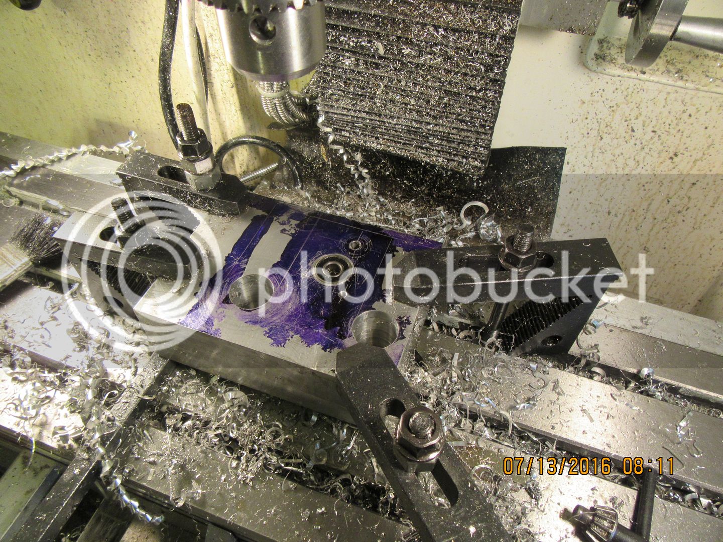
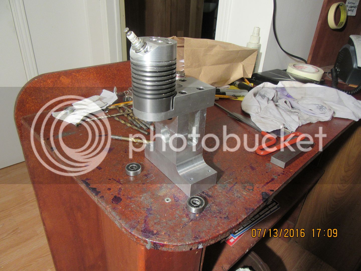
And---One hard days machining yields the frame. I don't have a lot to say about this---it's just a days steady slugging. One thing--My drawing shows 1/2" radii at the bottom of the vertical pillar. To get a 1/2" radius you need to drill a hole with a 1" drill. My old smaller mill couldn't have handled this easily if at all. So---If your mill blows fuses trying to drill a 1" diameter hole you might want to settle for 1/4" radius and drill thru with a 1/2" drill. And yes, that is one of the ball bearings setting in it's counterbore. I dropped it in for test fit after boring the hole and in it went---then I had no way to get it out until I removed the piece for a different set-up.

 
Brian,

" ...then I had no way to get it out until I removed the piece for a different set-up."

I have made some baby slide hammers for when this happens. The "hook" on the end can be tailored for different needs. I got my inspiration from both the big ones I used to use for car sheetmetal and the little ones my dentist uses when repeatedly trial-fitting crowns on my teeth.

--ShopShoe
 
My last big piece of bronze (the one that I scooped at the landfill) was 1 3/4" long x about 5 3/4" diameter. I had no way to hold it to slice it into two pieces, so today I made a LOT of chips. First shot shows it up on the lathe getting one side faced. Second shot shows it flipped around and the features cut into the first side. Then it was flipped around again and had the features machined into the second side. In one of those moves, it got turned down to 5.12" diameter and had the center hole drilled and reamed for my 3/8" crankshaft. and the third shot says WOW!!!! I still have a bunch of holes to put in, but that will be tomorrows job.
.

 
Brian, I would be willing to give this engine a try. Do you have the PDF'S posted somewhere or did I miss them? I am also assuming you are utilizing the throttle body carb. That Chuck Fellows designed and are posted in the downloads section.

Greg
 
Greg--First thing I suggest is that you read thru the entire thread. Most of your questions are answered in it. No I am not using the Chuck Fellows carburetor. No, I do not have all the drawings posted as pdf files. I would love to have you "On board" but you have to read the whole thread to get your answers. I will send you pdf files as I finish actually making the parts and "proving" the drawings. If you want to start building now, send me your real email address. I am creating pdf files as I finish the parts one by one, and will gladly send them to you. I have "proven" pdf files of everything I have built so far. Although it is unusual for my "first draft" drawing which I post on here to change, sometimes when I am making the part the drawings do change a bit for ease of machining or to add a dimension that I missed. It is these "proved and updated" drawings that become pdf files. I will be posting a link to all of the pdf files when the engine is finished, but if you want to "build along now" which I highly encourage, I will send you the pdf files as I finish each part.---Brian
 
Last edited:
The flywheel is finished. A lot of work in that, but it is one of the engines most predominant features. I made a few changes on the drawing as the machining progressed, but nothing major. I will now save that drawing as a pdf file and send it out to the folks who are building this engine "right now". I'm not sure what part I will do next, but it's probably getting close to "crankshaft time".


Today we have a pushrod guide finished and installed, and a crankshaft 80% done. when I make these pressed together crankshafts, I do not employ any heating or cooling. I turn the hole in the web to .0015" smaller than the finished o.d. of the shafts being pressed into it. A trick to help press things together and keep everything straight and true is to make the section of shaft being pressed into the web 3 times longer than the thickness of the web itself. Then, breaking that length up into thirds, turn the outer third to .002" smaller than the pressed diameter, the center third .001" smaller than the section being pressed, and the final third that actually gets pressed is left full size. Then while still in the lathe, a bit of sanding with a strip of 220 grit carborundum cloth removes the sharp edges at the changes in diameter on the shaft. This helps to guide the shaft squarely into the web plate. I coat the shaft with Loctite, press everything together, then let it set up for 24 hours and then cut away the extra bit of shaft which is left sticking out on the wrong side of the web.
 
Hi Brian, am enjoying following your rapid progress on this build! What sort of loctite are you using for things like the crankshaft? I can't make it out in the photo.

Cheers
James
 
Normally I use #638 for everything. This time I have a little bottle of "high heat resistant 620" that I'm using up. On press fits like this, I don't know if it helps any or if it all just gets scraped off. My theory is that it can't hurt, so I may as well use it.
 
Heads up, people---I just finished machining the ignition cam, and installed it and the ignition points for a test fit. The #6-32 thread for the screw that holds the points at the correct gap setting is not in the right place. It is close, but close only counts in horseshoes and hand grenades. I am going to drill and tap a new #6-32 thread immediately below the one which is already there, and that will center it in the slot, where it should be. I am going to update the drawing and resave it as a pdf file. What I recommend doing in this case is to drill and tap the #10-24 hole as per the drawing, make and install the cam, then install the points and "mark thru" the slot with a transfer punch to correctly locate the hole at mid slot when the rubbing block on the points is setting against the flat on the cam.---That cam also acts as a spacer to prevent the flywheel from rubbing on the end of the cylinder support plate.
 

Finally made a start. Unfortunately forgot the 1/4" radius.
 
Herbie--You may have trouble with the pressed in crankshaft. The two sharp corners you have created will be very close to the stressed area of the web. It may crack at one of the corners. That is why the radius was there.
 
This is what it looks like with the #6-32 threaded hole moved to the correct location to lock the points at whatever gap you choose. Also, if you remember, I changed the flywheel a little bit. That was to give good access to the points thru one of the holes in the flywheel as shown. I have corrected the position of that #6-32 thread on the pdf file of the main frame.

 
I was all set to get up tomorrow and start on a piston, but-----I checked my "left over short bits" drawer, and though I do have a piece of cast iron long enough to make a piston, sadly it isn't long enough to hold onto in my lathe chuck. So--Tomorrow I will be off bright and early to my metal supplier and buy a 3" length of cast iron. (which drives my metal supplier absolutely crazy!!):eek::eek:
 
Thanks for the info Brian. I shall make a new one with the radius. I hadn't thought about the stress in the corners.
 
My day went totally sideways. I couldn't make the con rod, because I'm still waiting for confirmation that I can get the oilite bronze bushings I need for it. I couldn't go and get the material to make a piston because I was waiting for a customers phone call. I ended up modifying the hub on one side of the flywheel to be .875" diameter, and then made the starter hub that fits on it. It turned out well, and has went into the pdf file.
 
Brian, you could make the connecting rod bushings of bearing bronze. I believe they would be a bit tougher than the oilite type. Granted you would need to make provisions for lubricating but that wouldn't be difficult. Another option would be to use a ball bearing on the crank end too.

Greg
 
So--Here we have a pretty good start on a piston. The raw stock was clamped in the 3 jaw chuck, then it was "faced" on the exposed end. Then the .875 flat bottomed counterbore was put in the end. Then it was turned to about 1.010" diameter. This is way too much material left on the outer diameter, but I have had enough bad experience with going undersize that I leave myself a good margin. This would never do in a "job shop", but since it's in my own little shop I can spend half an hour with 220 grit carborundum paper to bring it down to a point where it just starts into the cylinder. It won't slide in freely, but it will start in, which is all I want at this point. The ring groove has been plunge cut with my .093" wide parting off tool, and the piston is now finished externally. I'm not going to part it off yet from the parent stock. I may flip it end for end in the chuck and do a clean up pass on the remaining unturned portion before taking it over to the rotary table and mill to do the rest of the machining. I will think about that one overnight and finish the machining in the morning.
 
Last edited:
Brian, you could make the connecting rod bushings of bearing bronze. I believe they would be a bit tougher than the oilite type. Granted you would need to make provisions for lubricating but that wouldn't be difficult. Another option would be to use a ball bearing on the crank end too.

Greg
In my first "Rupnow engine" a few years ago which was a hit and miss horizontal, I used a ball bearing on the big end of the rod. It made the end of the rod so much larger, that combined with the weight of the bearing it was impossible to balance the engine. I specifically want to use oilite bushings to avoid lubrication problems at the small end of the rod, and if I use them on one end of the rod, it only seems logical to me to use them on both ends. I haven't heard back from my bearing supplier yet. If I can't get oilite bushings in that size, I will go without bushings at all on the con rod. 6061 aluminum stands up quite well without any bushings if it is kept well oiled.
 

Latest posts

Back
Top