Vertical I.C. Rupnow Engine

Home Model Engine Machinist Forum

Help Support Home Model Engine Machinist Forum:

This site may earn a commission from merchant affiliate links, including eBay, Amazon, and others.
Cogsy--if you can make it work with a CDI, then by all means go for it. I'm picking my points up today to see what they look like.---Brian


Hi Cogsy,

I am using CDI Kit from Howell Plans.
Now prepping for the first pop. Some wire connections to tidy up.
 
Hi gus--Glad to see you tuned in. I went in to tear down that last set-up, and fortunately I took a look at the drawing first and realized that I had to put in the bores and counterbores for the valve cages while still in that same set-up. Lucky I looked at the drawing!!!

I like building your engines because they are very forgiving. The Howell V-2 was very unforgiving but picked some new skills,polished up old skills and sort of tone down my impatience which led me to dimension errors. Read dimensions thrice,measure thrice and cut once and carefully. Plenty of tea/pee breaks. Ha Ha. I have one scrapped gear case and cover and four scrapped carbs. Sigh. After all these steep learning curves and trips, Gus kind learned fast.Ha ha. Take Care.
 
I have been asked about how I fit the piston to the cylinder. I haven't really got into piston/cylinder fits yet, but this is how I do it--the cylinder is finish reamed (or bored, I have a 1" reamer) to 1.000" diameter. After initial machining, a brake cylinder 3 stone hone powered by a variable speed drill is ran through it back and forth thru the bore dry at about 150 rpm, and only for about a dozen times to knock off any high spots. Do NOT let the hone spring out either end of the cylinder while you are doing this. A piece of 1" diameter aluminum about 6" long is 'polished' with 220 grit carborundum paper until it just fits into the end of the cylinder. (this will mean that the 1" aluminum will be at about 0.998" diameter.) The very end of the aluminum is chucked in the lathe, and coated with a slurry of 600 grit carborundum paste and oil, and with the lathe NOT RUNNING the cylinder is held in your hand and slowly pushed and rotated onto the aluminum until it will fit right over the aluminum and have about 1" to 1 1/2" of the aluminum sticking out the other end of it. This is a slow procedure and not a lot of force should be used. It will feel tight and gritty at first--it is supposed to--You are polishing the bore to take it to a very smooth finish. Once the cylinder can be moved from one end of the aluminum to the other without "grabbing", remove it from the round aluminum completely and start the lathe at a low 50 to 60 rpm. Add a little more slurry to the aluminum surface. Very carefully slide the cylinder over the revolving aluminum and slide it back and forth about 20 times, making sure to not slide it so far that the aluminum disappears into the bore. Be ready, if it grabs, to let go very quickly and shut down the lathe, then work it off by hand. This is very dangerous and scary as Hell, but it's the way to do it. Turn the piston outer diameter down in very small increments until it just starts into the cylinder bore but doesn't slide in. I have made up a handle somewhat like a long connecting rod with a T handle on the end of it. I put the handle on the piston with a short piece of material to act as a wrist-pin, put the cylinder into the lathe 3 jaw, and coat the bore with a bit more slurry. Using the T handle, with the lathe OFF, work the piston back and forth thru the bore until it moves freely. Once this is done, wash the inside of the cylinder and the outside of the piston with soap and water and scrub with a toothbrush and wipe with laquer thinners, to be sure to remove any remaining carborundum paste. Now--You are set up to use a Viton o-ring for your piston ring. The procedure is the same for the piston regardless of whether it is cast iron or aluminum. This will be a relatively slow revving engine, so we are not worried about the mass of the piston, and as I said in an earlier post, cast iron has it's own inherent lubricating properties because of the graphite which is part of its metallurgical make up.---Also---the crankshaft web has a pretty massive counterweight built into it, so I like the mass of an iron piston to avoid over-counterbalancing the engine, as might happen with a light aluminum piston.------------Lubrication--Well, the crankshaft runs in sealed ball bearings, so needs no lubrication. Both ends of the con-rod are going to be running sintered bronze Oilite bushings, so a squirt from an oilcan before running will be quite good enough. The camshaft doesn't rotate. It is stationary, and the exhaust cam is bolted to the face of the cam gear, which rotates on an Oilite bushing. And--I always run about a 50:1 mix of synthetic 2 cycle oil with my fuel to lubricate the Viton ring and the piston/cylinder interface.
 
Last edited:
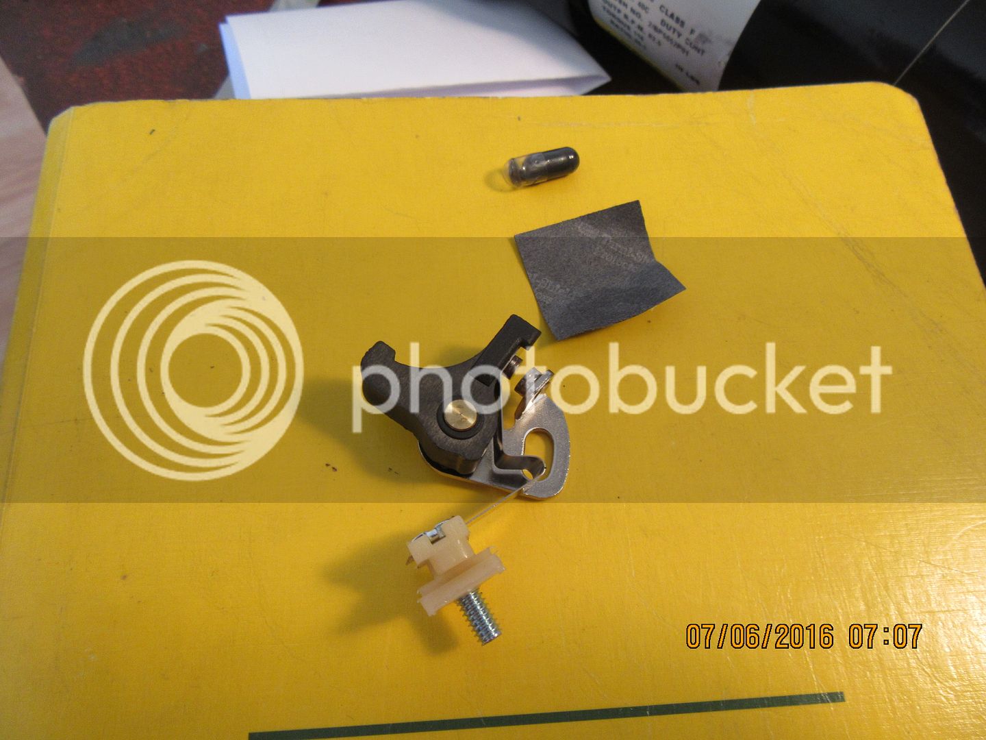
I just received my Tecumseh ignition points #30547A for use on this engine. I can probably figure out a mounting system on my own, but I would really like to see someones installation of these points either in an engine they have built or in an original engine. These points don't rub on the ignition cam. They are remotely mounted, and a pushrod opens them. I can only assume that the other end of the pushrod rides on a cam, but I would really like to see some pictures of the points, pushrod, and cam mounted. I did a Google image search and although I found a thousand pictures of the points, I didn't find any of the points "in place". Can someone help please.----Brian
 
Last edited:
The 1/8" i.d. x 1/4: o.d. roller bearing which goes on the end of the pushrod is no longer carried at Busybee Tools. I have found an alternate supplier of the same size bearing made by INA part number #R144-2Z. They are $5.40 each, minimum quantity of 5 on each order. I will buy a package, and when anybody gets far enough with the engine to need one, I will mail one to them.
 
Guys, somewhere along the way, I got lead down the garden path. It was my understanding that the Tecumseh points were operated by a pushrod which rode on the cam. I was wrong. I'm busy on some "real work" for a couple of days, but will sort the points out next week. thanks for your help.---Brian
 
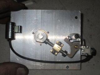
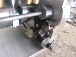
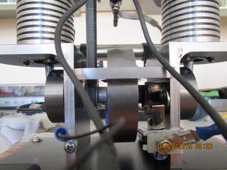
The Tecumseh points set rub block is actuated by a points cam directly. On your WEBSTER, with outboard mounted points per plan, you can set the Tecumseh set up against its cam for a clear view look/see. Or they can be mounted away from the cam and actuated with a push rod as I had to on my FOREMAN engine to gain clearance from the crank web as the ign. cam is mounted to the crankshaft. I use these points for their compact size as my engines have an open crankshaft where I can mount the ignition inboard pretty much out of sight. I also have to make sure I have access to the screw that sets the points gap. Outside of the engine block their mounting is the same as automobile points on a model engine and driven by the crank or camshaft.

Points driven by crankshaft on FOREMAN engine using pushrod.

Points driven by camshaft on OVERTIME engine.


Points between end plate and flywheel on SUPER H.

Looking at your new model Brian, outboard of crankcase behind the flywheel for the ignition with access to set the gap through the slots/ spokes of the flywheel looks good.:)-----Dave
 
Last edited:
Too soon we get old---Too late we get smart----These are the points I was thinking about that are operated by a pushrod. Look at the way they mount. Instead of a "flange/face" mount like the Chrysler and the Tecumseh, these ones mount at 90 degrees, which is what I actually wanted. I will call and get a price on them tomorrow.
http://thumbs2.picclick.com/d/l400/...-Deere-Original-Equipment-Point-HE1601183.jpg
 
A little of the rationale behind using a roller on the end of the pushrod. If the cam has curved sides on it, then the lifter can be flat on the bottom and not need a roller. However, cams with curves sides are relatively complicated to make. Now, if you used a flat sided cam with a flat bottomed lifter, then every time the cam revolved, the flat side of the cam would "slap" the flat bottomed lifter, and make it bounce. That would cause problems. However, if the cam is made with flat sides and used with a cam follower bearing instead of a flat bottom lifter, then the "roller" will ride up and down, following the contour of the flat sided cam closely without the "slap and bounce" that you get with a flat sided cam and a flat bottomed lifter.----Brian
 
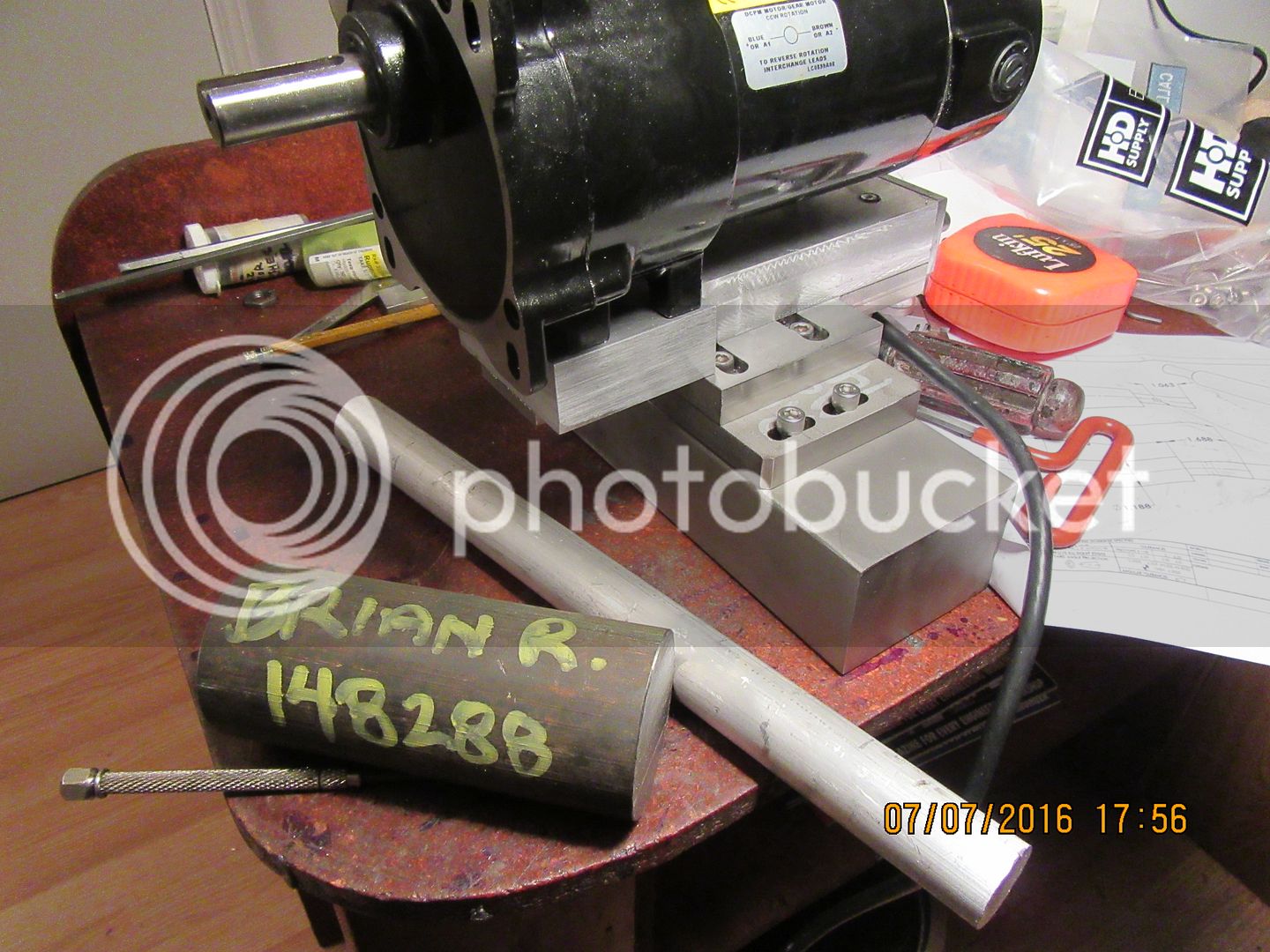
Wish me a Happy Birthday people. I'm 70 years young today!!!--Nothing new to report on the vertical engine, as I've been busting my buns machining the stuff in the background of the picture for a customer. However, I did buy the cast iron for the cylinder and the 1" aluminum round to do the preliminary lapping with. For interests sake--When you buy 2" diameter cast iron, it actually measures 2.125" diameter "in the rough" so it will clean up to 2" when you machine away all the rough surface.
 
Great achievement on reaching your 70 th. Hope there are many more to come.
Norm
 
Happy Birthday Brian!

I've been lurking for the last year or so on the forms, following the last couple engine builds you've done as well as those of Gus and the other guy (can't remember his name) doing one of the Howell engines.

I am going to try and build this engine as well, just printed off the drawings and getting ready to head out to the shop to see what I have on hand - right after I walk the dog.

Not sure about the gears, at least in terms of finding reasonable priced cutters - are yours an import set and if so where did you buy them. And are yours 14.5 or 20 degree pressure angle? and does it even matter what pressure angle one uses. Its been close to 30 yrs since I last cut a gear when I was still living in the great white north and taking high school machine shop. They don't even teach gear cutting anymore in the high school shops down in the south here. I retook high school machine shop with my eldest son this past winter (he's just starting out as an apprentice machinist) and they don't even talk about gear cutting anymore. Seems like a lost art. I just need this as an excuse to wire up my horizontal mill and get it running again - its been disconnected from power since I stole its VFD to power my new (to me) lathe.

Thanks for your awesome build threads.
 
Mjonkman--I bought my gearcutters through Travers of Canada, and they weren't cheap. I've had them for about 5 years now, and I think I paid about $500 for a complete set of 8 cutters. I have a catalogue here from W M. Berg, which is now division of RPM mechanical in Burlington, Ontario, and it does list the 15 and 30 teeth gears with a 3/16" face in a 24 pitch, but the bores are only 3/16", (but could probably be opened up). I build so many things that I decided it would work in my favour to buy a complete set of cutters. I don't think it matters if they are 14.5 degree or 20 degree pressure angle, as long as the two gears match.
http://www.traverscanada.com/involute-high-speed-steel-gear-cutter/p/10-281-240/
 
Last edited:
Here is a link to what appear to be reasonably priced 24 dp gears. The bore on the large 30 tooth gear is 3/8" which would be fine, as it allows for a bronze bushing. The bore on the small 15 tooth gear would have to be opened up to 3/8". If you don't have gearcutters, this seems very reasonable.
https://www.amazon.com/dp/B007NO73R4/?tag=skimlinks_replacement-20
 
Last edited by a moderator:

Latest posts

Back
Top