Vertical I.C. Rupnow Engine

Home Model Engine Machinist Forum

Help Support Home Model Engine Machinist Forum:

This site may earn a commission from merchant affiliate links, including eBay, Amazon, and others.
I agree with the aluminum for a bearing, Brian. Decades ago I built a rock
crusher with an aluminum eccentric bearing and it worked fine.

By the way, have you thought about using needle bearings instead of ball
bearings? I've thought about those because they're lighter in weight and
take up a lot less room. But I've never tried them..... at least not in a model
engine!

Take care,
Pete
 
Pete---Here's the scoop on needle bearings. Needle bearings are meant to run on a hardened shaft. If they run on an unhardened shaft, they will gall it very quickly. If you don't have a hardened shaft, then you can buy a hardened inner race, which of course bumps up the overall size of the bearing, to the point where it becomes as large in diameter as a ball bearing. Needle bearings are meant for a rotating shaft, not an oscillating shaft as you have in the small end of a connecting rod. Used in an oscillating situation, the needles develop "flat spots" on them and won't rotate at all. Nobody currently makes sealed needle bearings for a 3/16" diameter wrist pin anyways.---And lastly, needle bearings are noisy as Hell. I know--I put a set on my Kerzel hit and miss engine when I built it 5 years ago, trying to get more "misses" between 'hits" by cutting down on the rolling friction. It helped, friction-wise, but I was amazed at how much noise they made. I believe that if they had been installed in a cartridge type holder where they could be pumped full of grease they might have been quieter, but with oil from a squirt can they make a real racket.--That sums up everything I know about needle roller bearings.---Brian
 
I agree, they wouldn't work well on the small end. I was thinking more
of the big end, but as you point out finding sealed units isn't the norm with
needle bearings. No real gain then.....

Thanks,
Pete
 
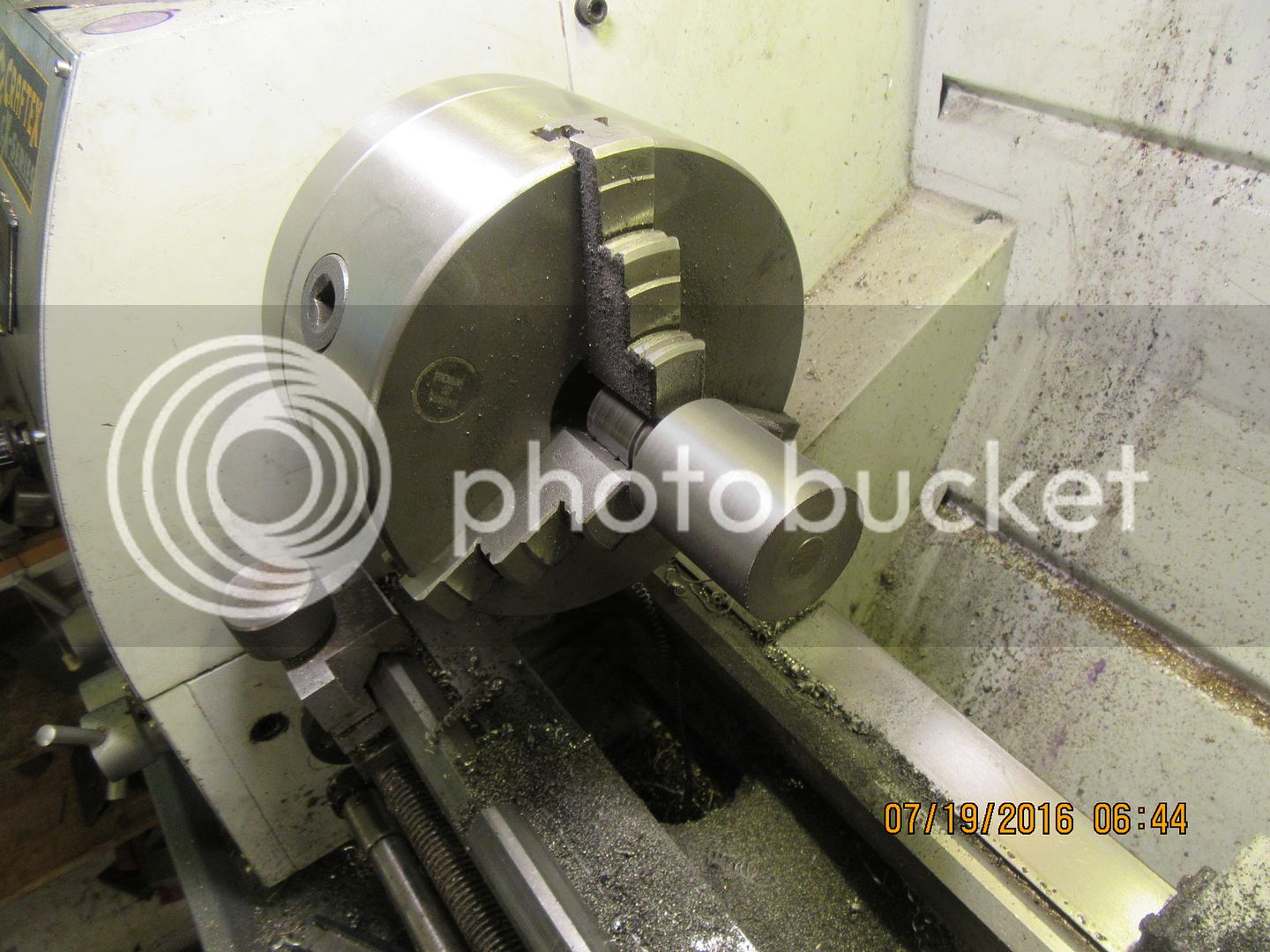
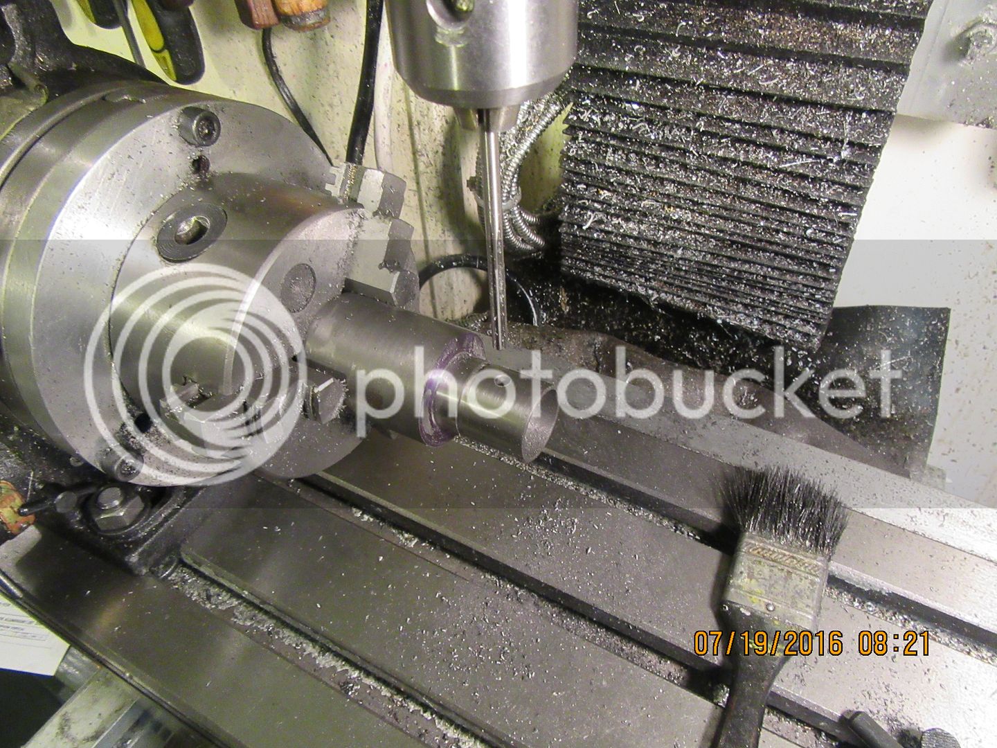
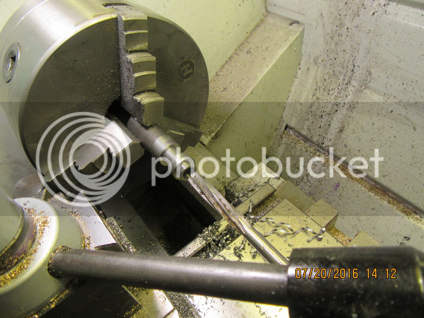
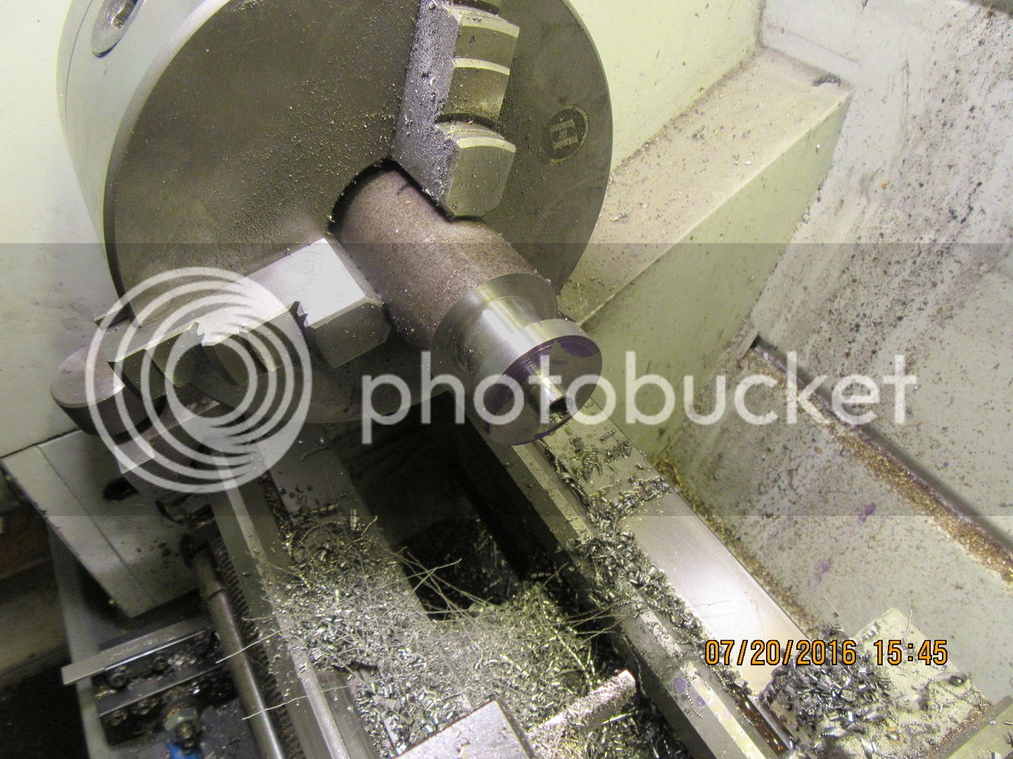
I thought about it overnight, and decided that the correct way to do this would be to flip the part end for end in the chuck and clean op the other end. I should really have done this before I got the piston down to almost finished size, but I clamped carefully on the piston and took light cuts until the other end of the material cleaned up quite well and was "faced" in the same set-up. I did not take any picture of the part set vertically in the rotary table to mill the slot. In the second shot, you see the rotary table turned 90 degrees and bolted down, and the wrist pin hole being reamed to final size.

 
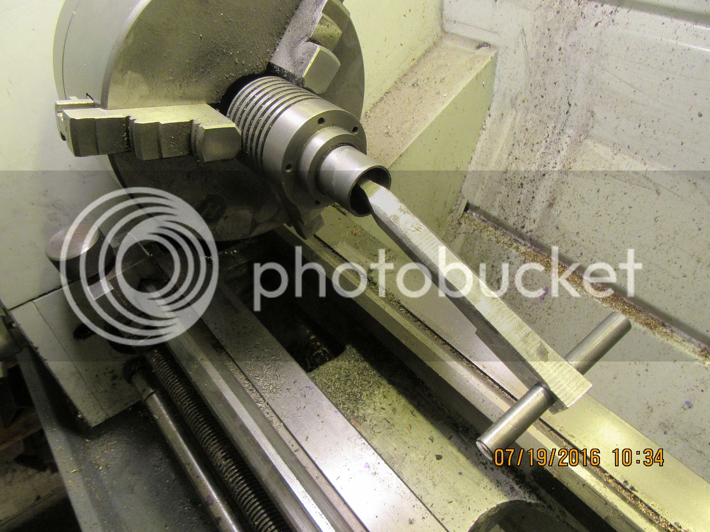
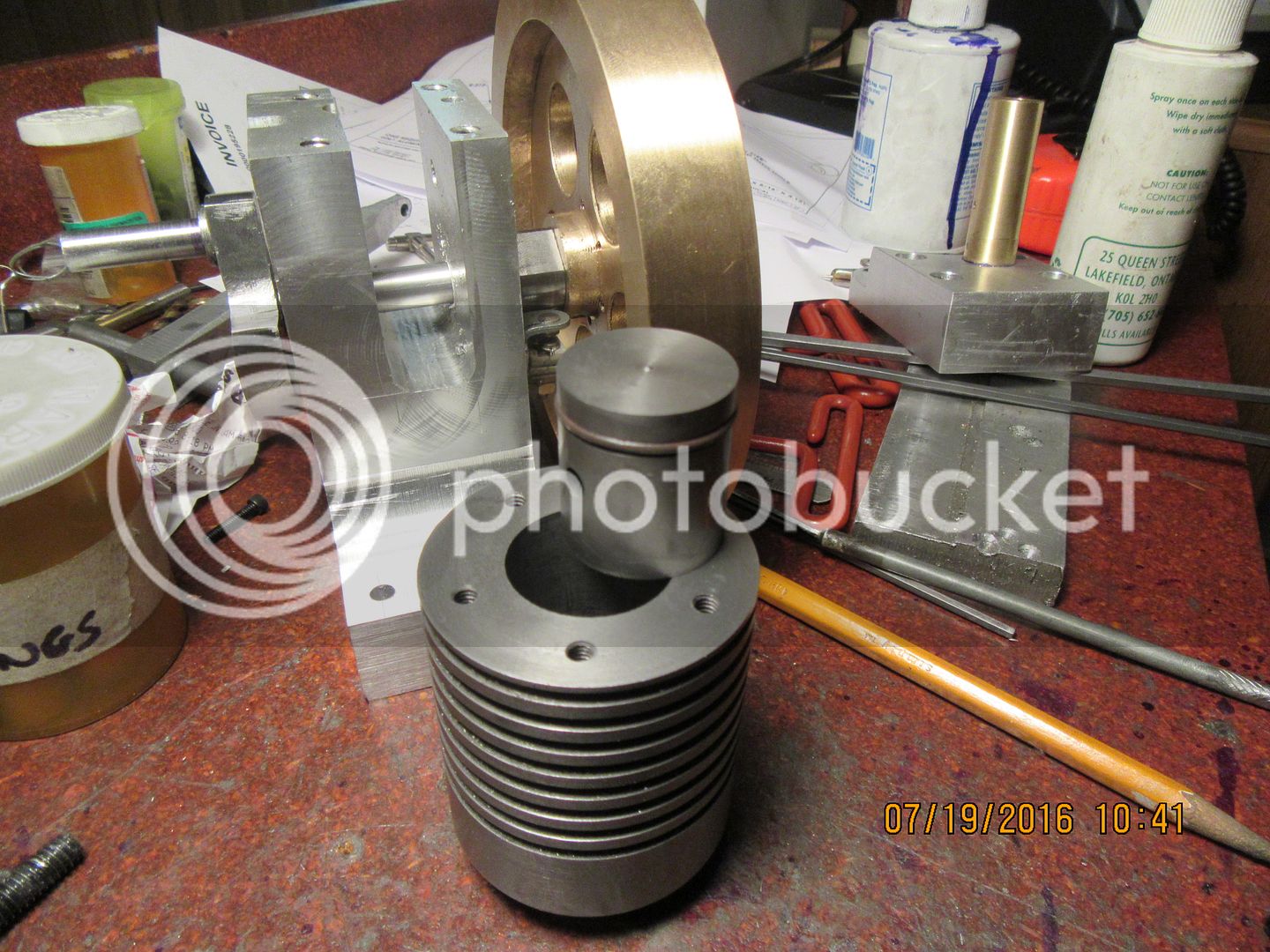
The first picture shows the piston being lapped into the cylinder. As luck would have it, the piston was still a bit too large to fit into the bore (I couldn't really check that until I had parted it off from the parent stock). This demanded that I put the piston back in the 3 jaw and work it a bit more with 220 grit carborundum paper, first one end, then the other until it was down to 1.002", at which point it was much happier about starting into the cylinder. This is a very difficult point to judge. Too tight, and you will get the piston stuck in there and have to press it out with a length of wooden broom handle. Too loose, and you have to start over again and make a new piston!!! This one turned out "just right" and the final lapping was done with 600 grit carborundum grit suspended in white grease. I run the lathe on it's slowest speed setting (50 rpm) and very carefully work the piston in and out with that T handle which attaches to the wrist pin, watching very carefully how my hands are positioned and ready to let go in an instant if the piston "grabs" in the cylinder. The resulting piston will not fall thru the cylinder, but will go thru with a gentle push from my finger. the last picture shows the piston with the Viton ring installed on it.

 
I just received confirmation from my bearing supplier that the oilite bronze bushings I need do indeed exist in the size I wanted, so I have ordered them and they will be here on Thursday or Friday. the only "catch" was that I needed to order a minimum quantity of 5 of each size. The longest cam gear bushing available was 1/2", so I will use two of them end to end in the cam gear. The cost for all of the bushings was about $20 Canadian.
 
I know I posted yesterday - but I can't find my post anywhere in the thread :confused:...weird. Anyway, I'm glad the bushes are available as I've already made 4 con-rods (to get an acceptable one) and didn't fancy making another.

I have the flywheel half done in a built-up fashion but I think I've worked out how to modify it for the new hub dimension. On the flywheel drawing I couldn't find a bore dimension - not a problem but you do normally dimension everything so I thought I'd mention it.

Finally, I may not be able to afford the material for the frame right now (I am a very poor student these days) so I may have to go the casting route but it will be quite a while before I have casting capabilities again. For now I'll just keep working on the smaller pieces.

Keep up the good work Brian, I'm thoroughly enjoying this build!
 
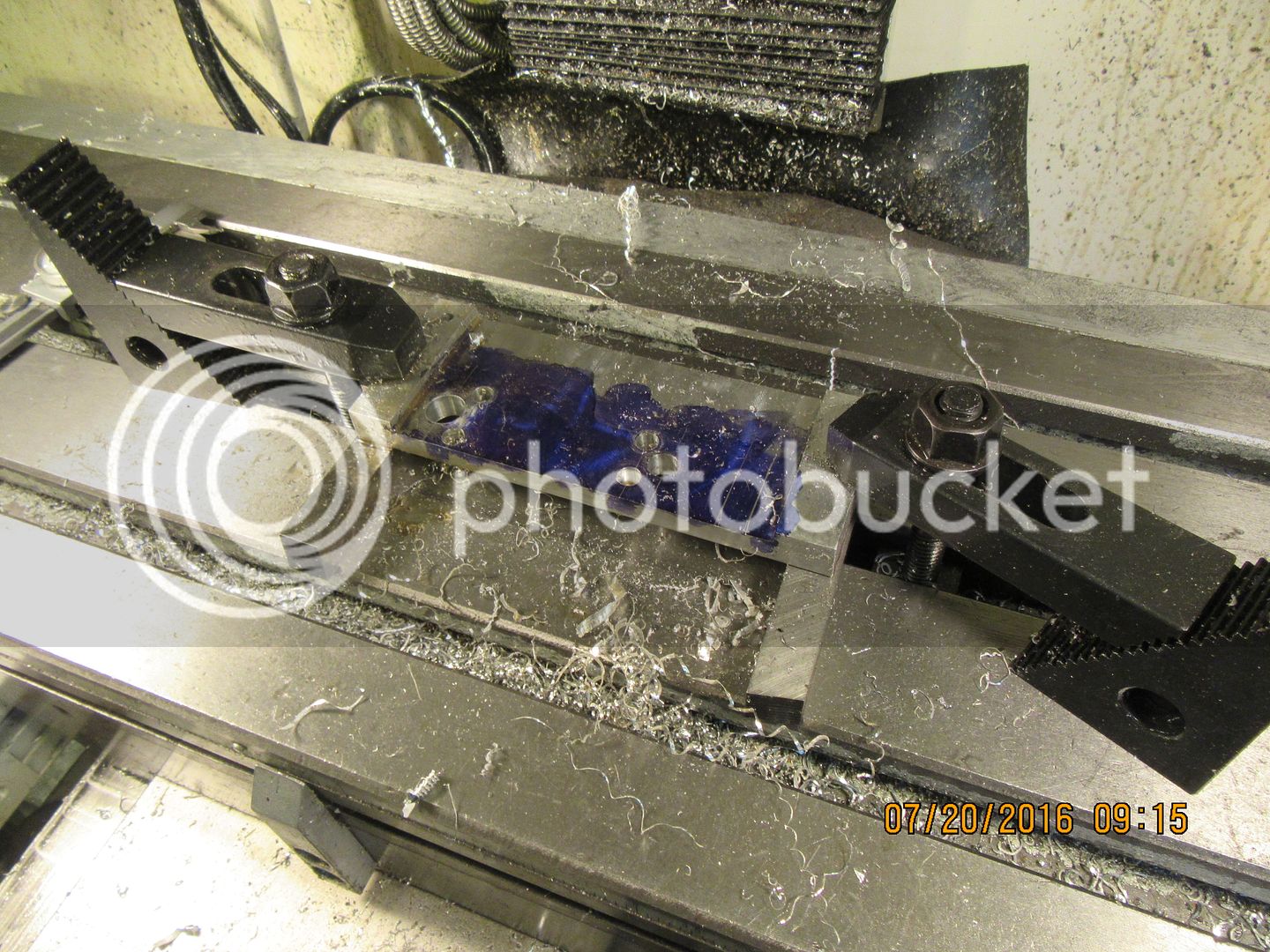
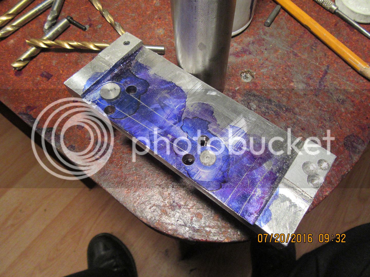
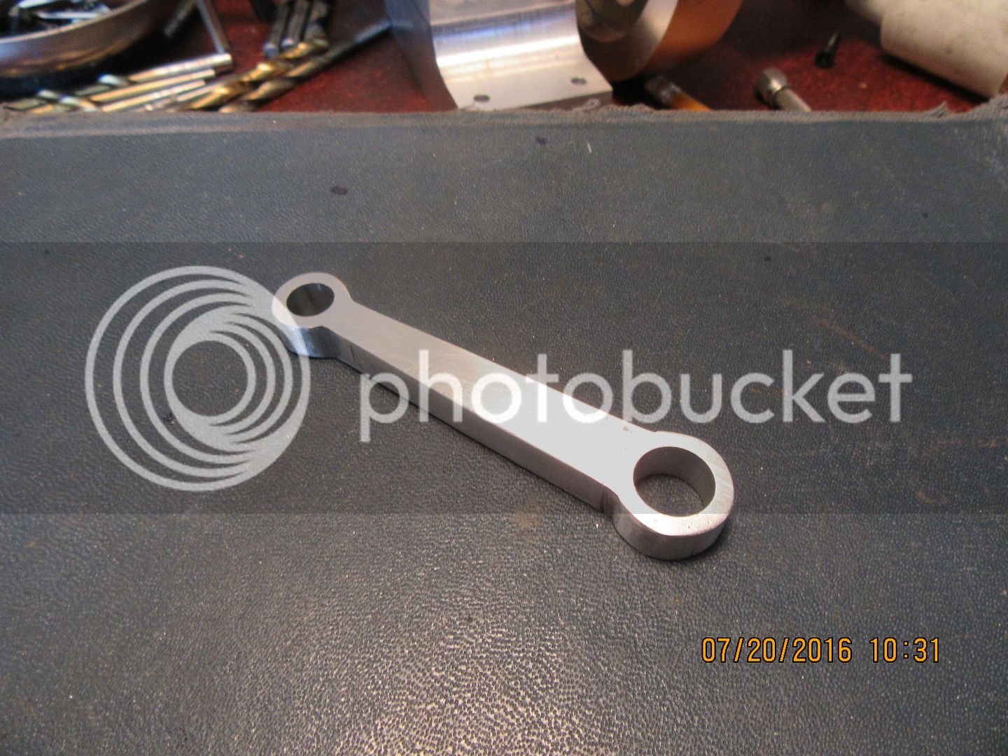
As far as I know, you can't buy 5/16" aluminum plate--at least I can't at my local metal suppliers. So--there are a couple of things going on in the first picture. #1- is that I found a scrap of 1/2" aluminum plate and used my flycutter to reduce it to 5/16" thick in the center where I will cut my con-rod from. #2- is that whenever I drill holes in a plate that are critical in their 90 degree relationship to the plate they are drilled in, I don't use my milling vice. (It always "cocks" a little bit, which for 95% of what I do doesn't matter that much). I put a piece of sacrificial plate (or in this case a 1/2" square spacer under the piece I am going to drill and ream and clamp it directly to the mill table). In the second picture, the holes are drilled and reamed, and I have inserted a pair of "temporary centers" in the reamed holes, so I can stick one of the points on my drafting compass into the center "divot" and draw the arc at each end which shows the ends of the con rod. I also use a straight edge to connect the clearance holes at each end which form the 1/8" radius. Then with mostly bandsaw and stationary sanding belt I cut away all the excess material, and finally a bit of filing and hand sanding to yield the finished connecting rod.


Cogsy--thank you for the heads up about the missing flywheel bore dimension. I have added it and sent out a new pdf to all of the folks who are currently building the engine.---Brian
 
  • Like
Reactions: gus
5/16" bar stock is available here in the US at both McMaster Carr and OnlineMetals the two places I get a lot of my material from. OnlineMetals also has plate but ouch is it expensive.

Do you know what the oilite bushing numbers are?

Hope to be back up and running with my mill by end of next week so starting to look through the various drawings to get material sizes so I can purchase the rest of the materials, bearings and bushings.
 
I will know later today or tomorrow morning what the oilite bushing numbers are. I just order by i.d. and o.d and length, but my bearing people will have the correct numbers and I will let you know.
 
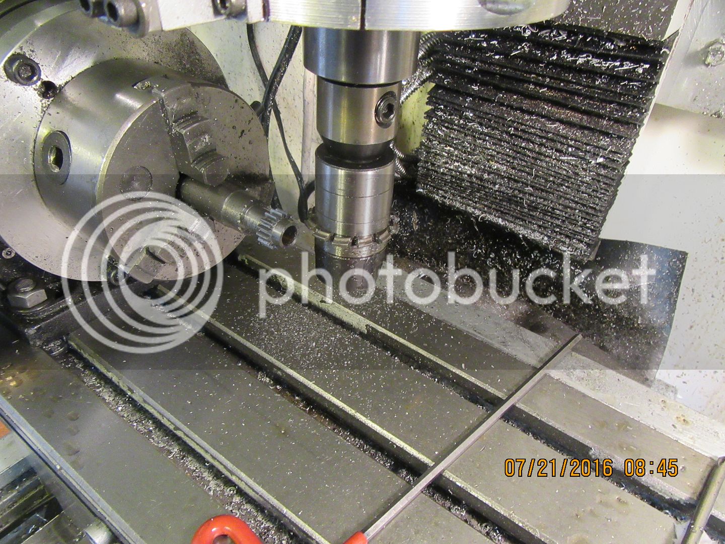
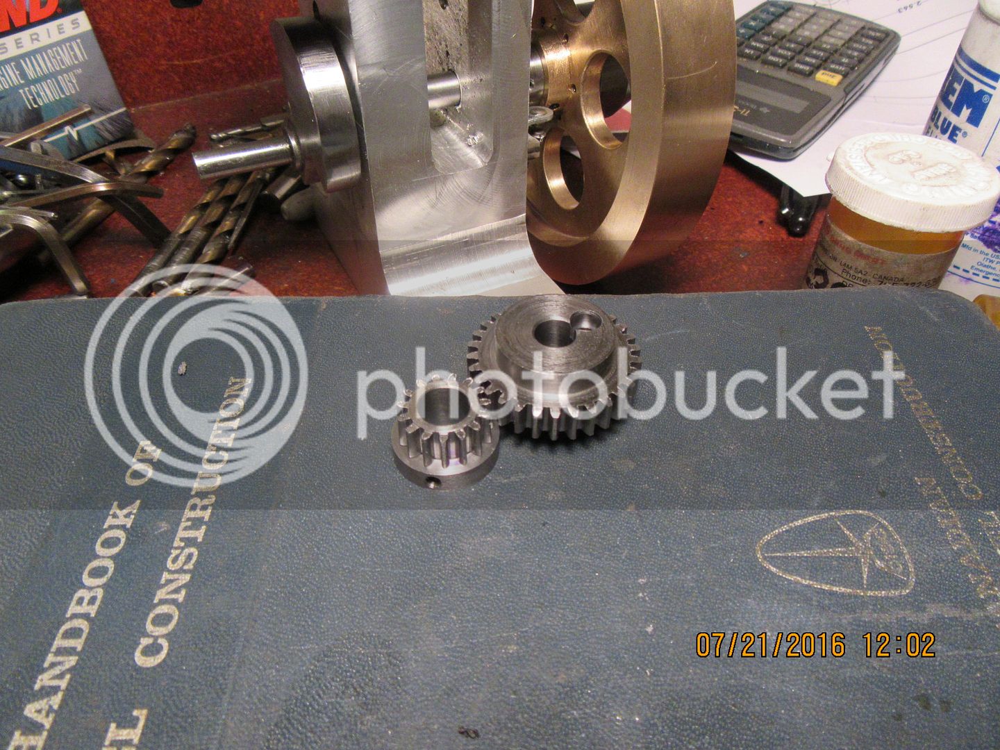
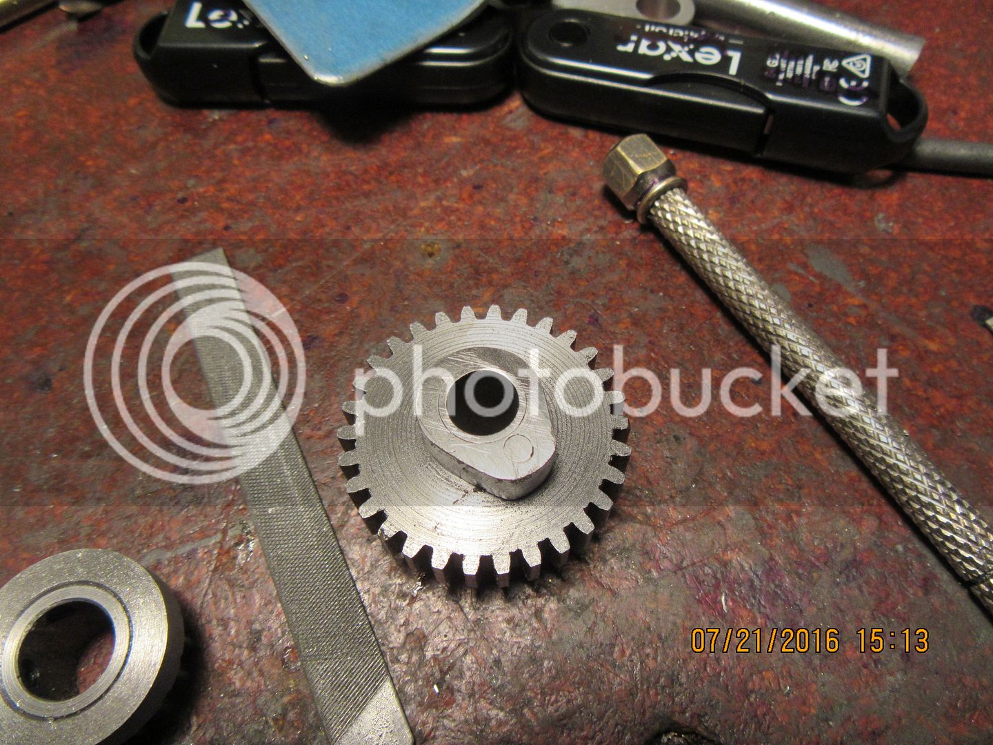
The gear cutting went very well. I have a set of dummy shafts set up at the correct center distance in a scrap of aluminum plate, and all the gears I cut are checked for correct mesh before I tear down my rotary table set-up. The second picture shows both gears finished, and the hub ring attached to the smaller gear. I'm probably going to go ahead and finish the valve cam and install it on the large gear before I install the gears in the engine. I still don't have my oilite bushings anyways, so I may as well get the cam finished now.

 
RATS!!!! I went down to southern Ontario today and met an old friend I used to work with at Volkswagen of Canada, for lunch and a visit. The plan was to be back in Barrie before 4:30 to pick up my bronze bushings. I forgot to factor in all of the traffic heading north up to cottage country on Friday afternoon. Never made it back to Barrie until 5:30, and my bearing supplier was closed.---So---No bushings till Monday. I'm rapidly running out of things to build, so I guess tomorrow I will have a look at valve cages and valves.
 
  • Like
Reactions: gus
Heads up--I plan on making valve cages tomorrow, and on close examination of the drawings, I have decided to make a change in the depth of the 1/4" counterbore. If anybody has already made them, don't be concerned, they will work as originally drawn. As soon as they are finished and installed in the head and drilled, I will post a revised drawing and save it to the ever growing pdf files. In the original drawing, the counterbore extends 0.159" below the bottom of the drilled 0.197" cross hole. There is no reason for the counterbore to be so deep, and by shortening the counterbore by 0.100" it gives more guidance on the valve stem and less possibility of air leaks around the valve stem. ---Brian
 
  • Like
Reactions: gus
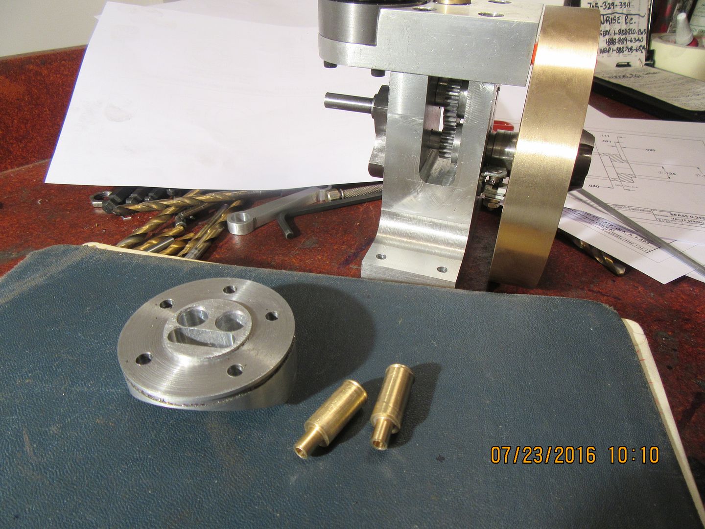
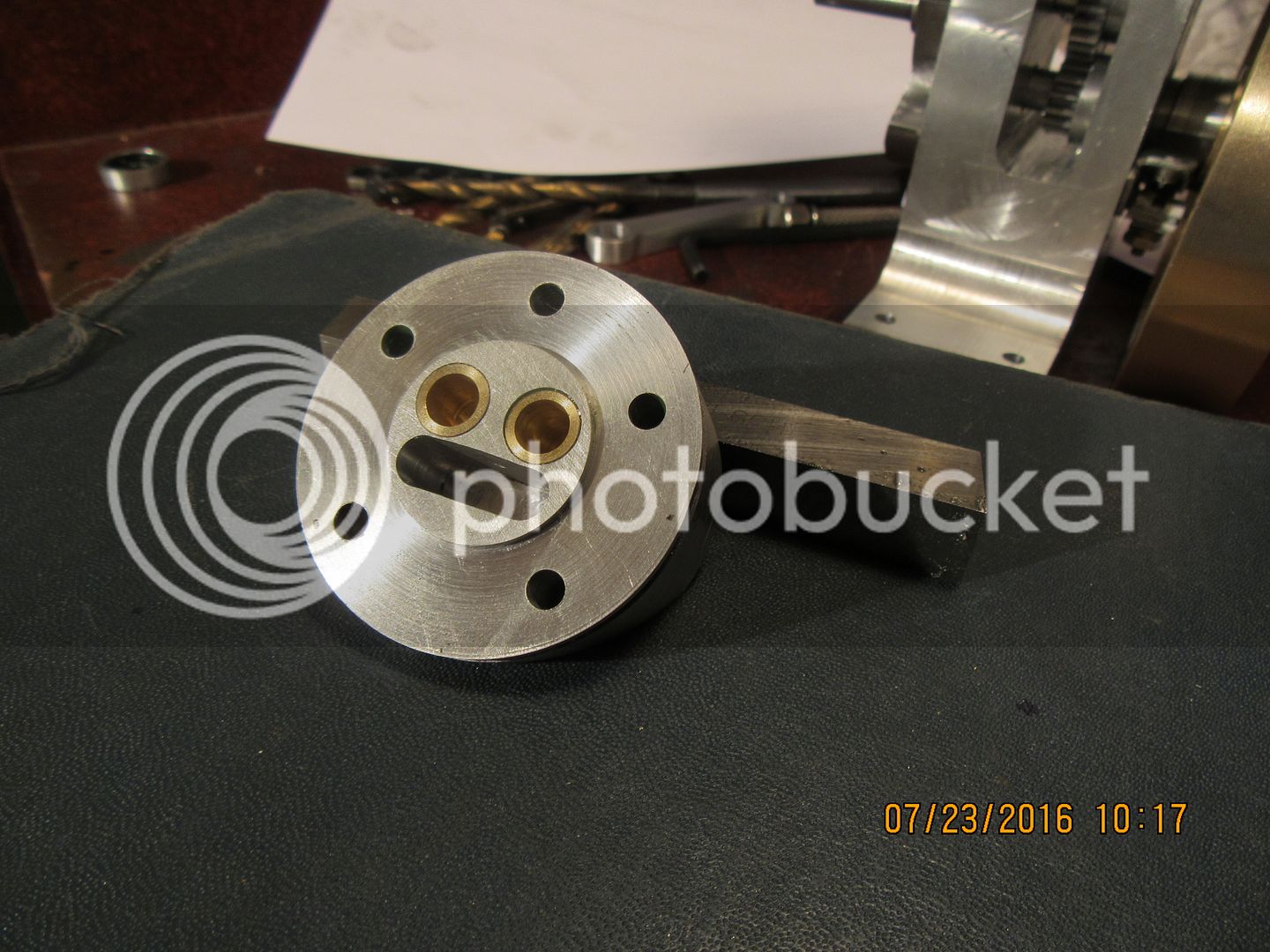
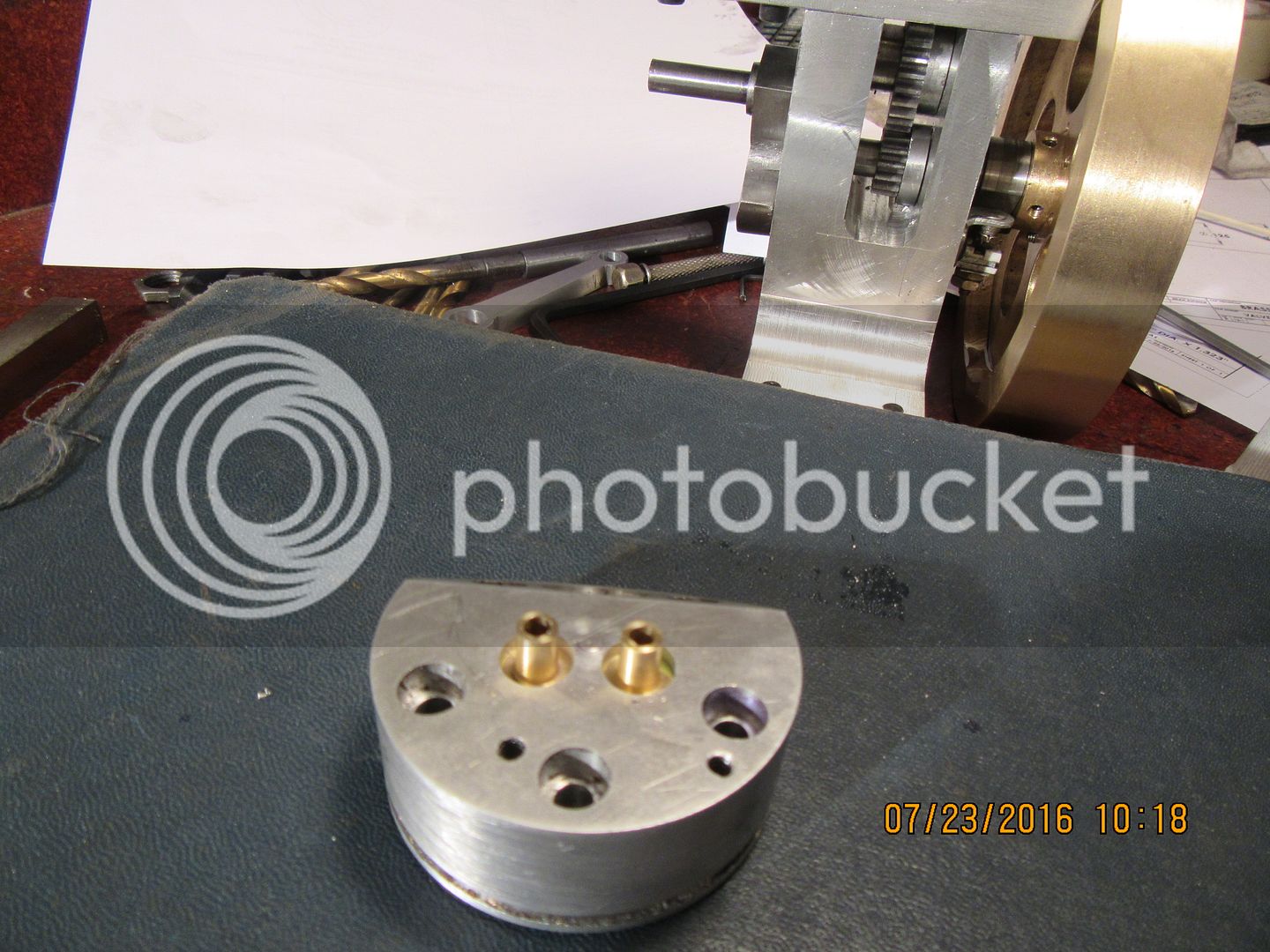
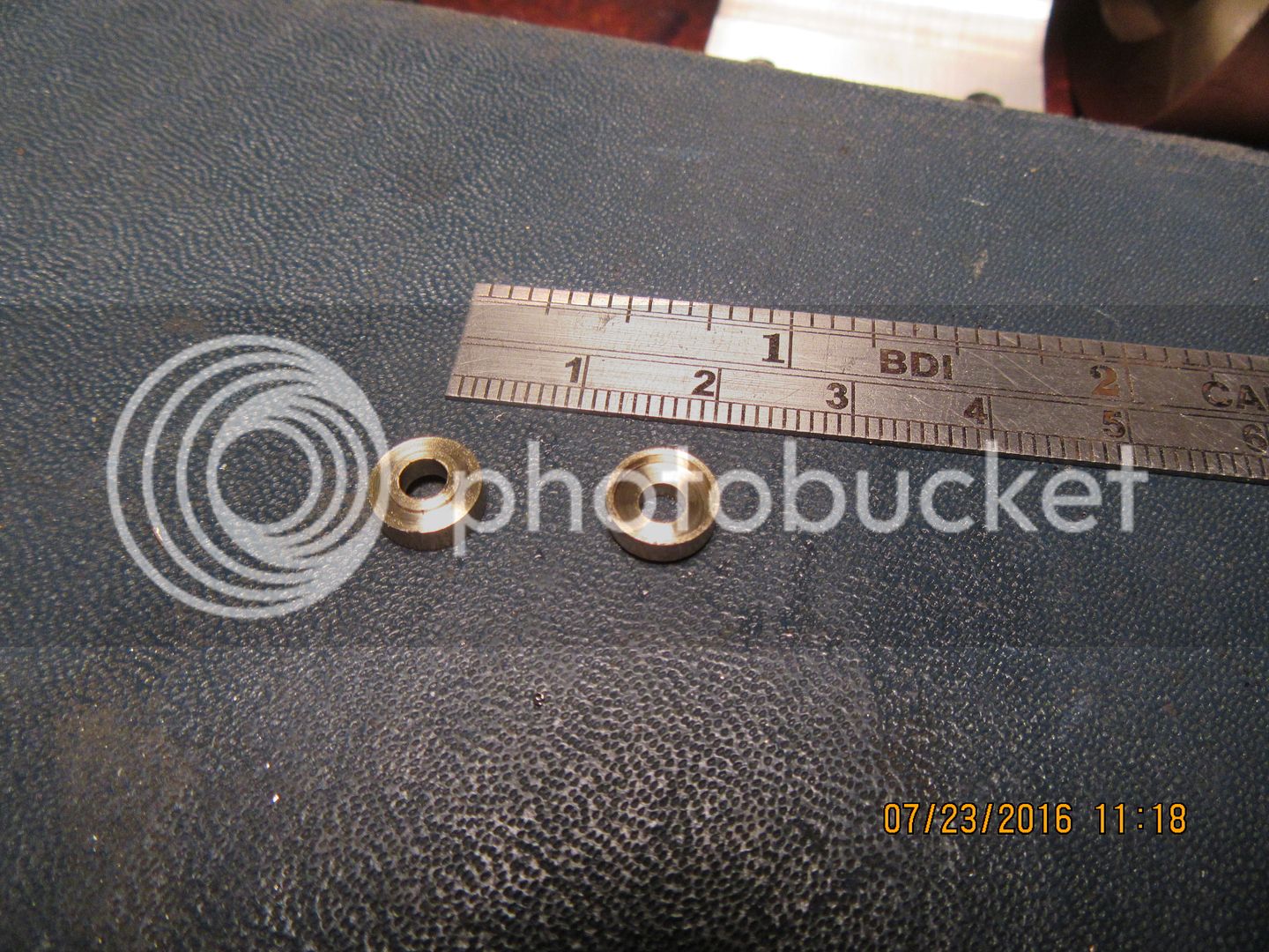
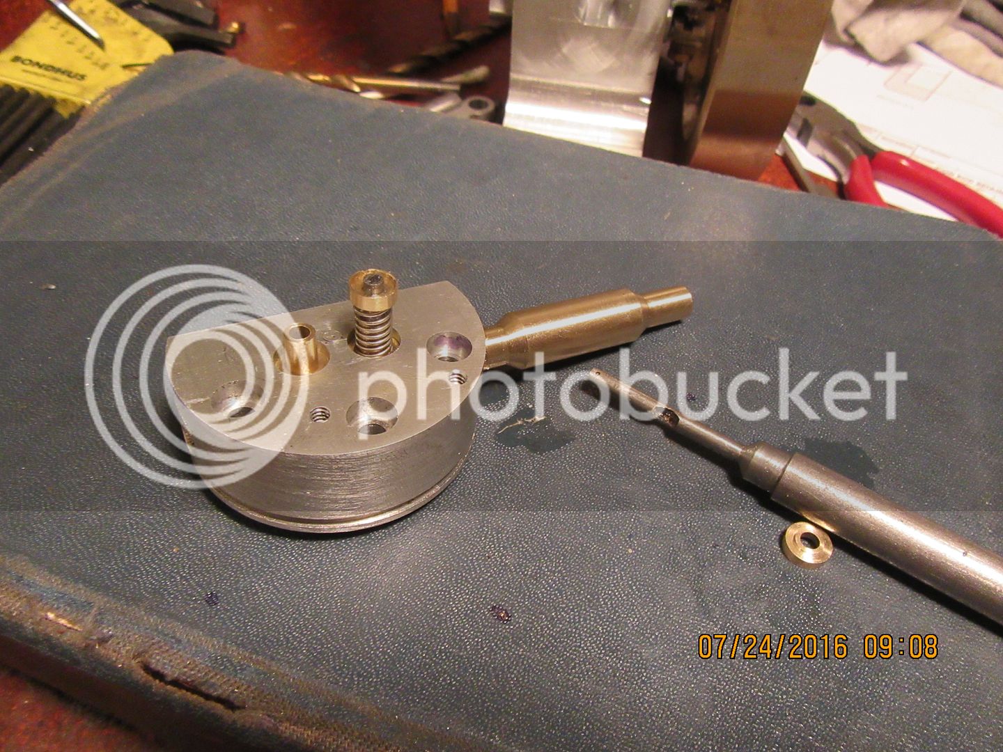
This morning I made the valve cages. They are machined outside completely, and inside all except for the very narrow .015 x 45 degree chamfered face which the valves seal against. In this picture I have washed both them and the cylinder head in laquer thinners to remove any trace of oil. In the background, you can see my gears from earlier in the week setting in place in the engine. (Although since I don't have bushings yet, the cam gear is just setting on a dummy shaft.)The valve cages have been test fitted into the bores in the cylinder head, and although they are not a "press fit", they don't fall freely into the bores either. It is very important to test fit them and be sure that the .020" "lip" around the end of the valve cages fits into the counterbore in the head and does not stick up above the inner head surface. In the second two pictures, the cages have been coated with #620 Loctite retaining compound and inserted all the way into the cylinder head. After the Loctite sets up for 24 hours, the fuel admission port and exhaust port will be drilled thru the cylinder head and thru the valve cages at the same time.


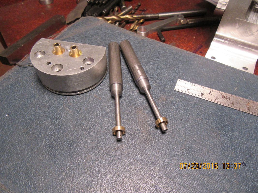
And here we have two beautiful valves with their "handles" still attached (so I can lap them into the valve cages tomorrow) and two keeper plates to retain the valve springs. Quite enough work for another lovely Saturday!! Time to grab a cold beer and relax with good wife on the back deck.

 
Note to self: when using a valve as one of the set-up guides to drill the ports, remember to REMOVE THE DAMN VALVE before actually drilling the port!!!
 
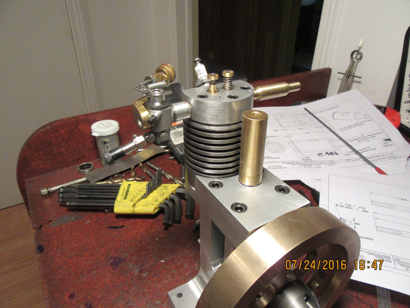
Well, I worked past that mini-disaster and whittled out a new valve to replace the one I destroyed. The ports ended up exactly as they were supposed to, which is always a good thing. I have to go down to my nut and bolt supplier tomorrow and buy a .015" wire diameter compression spring for the atmospheric intake valve. I will post the specs for both the intake and exhaust valve springs after I get it. If I get my oilite bushings tomorrow I should be able to install the connecting rod and the cam shaft. All I have left to make is the rocker arm and rocker arm support tower, and the push-rod. Since I have already built the carburetor a number of times and know that the drawings for it are correct, I may take a short-cut and use one of my model airplane engine carburetors to start this engine later this week. I will post all the details about the Traxxas 4033 carburetor and the adapter to fit it to the engine as soon as my camera batteries charge up. These carburetors only cost about $35 and are perfect for all this size of engine. I will put all the drawings of the "home made" carburetor in the download package, and that way builders will have a choice of buying or building their carburetor. I may wait for the cold weather next winter to build the carburetor.
 
Last edited:

Latest posts

Back
Top