Vertical I.C. Rupnow Engine

Home Model Engine Machinist Forum

Help Support Home Model Engine Machinist Forum:

This site may earn a commission from merchant affiliate links, including eBay, Amazon, and others.
Congrats Brian for the project of the month,

David Lloyd,
 
Made a start on the carby body. Started with some 1" round drilled centre and turned a couple of spigots down to .591". Then onto the mill to machine the square part to .591".

Then after a day of machining we have
 
Okay, all of you Canadian guys!!--I'm not just another pretty face. I just got my copy of the October/November "Our Canada" magazine, and a couple of my "Short stories" appear on page 62, titled "Grandpa has a blast". They got it mostly right except the very last paragraph. This is one of the first "non technical" articles that I have had published.---Brian
 
For those of you who are toiling away on this build, I have a bit of advice for setting up the carburetor to run the engine. For an initial setting, open the needle valve one full turn. Set the throttle to about 1/4 of the way open. If you are lucky enough to have the engine start and run (hope--hope---) then let the engine warm up. Try screwing the needle valve in or out SLOWLY until the engine seems to be running at it's best. Back the throttle off until the engine is running at a medium idle, and set the idle adjustment screw so it prevents the throttle from closing any farther. At his point, you can start adjusting the air bleed screw. You will find that there will be a point of adjustment on the air bleed screw where the engine begins to rev faster. When this happens, adjust the idle adjustment screw to slow the engine down to it's original idle speed. Keep adjusting the air bleed screw until it doesn't change the engine rpm any farther, and lock it down there. I used the springs out of a pair of ball point pens and slipped them over both the idle adjustment screw and the air bleed screw, (captured under the head of the screws) to keep the screws from vibrating out of position. You will find that you probably have to cut the springs to the correct length.
 
Thanks Brian. Im still working on the carby. Ver fiddly little thing but getting there slowly.
 
Not much but some progress to show ,

DavidLloyd,

DDT_5190.jpg


DDT_5195.jpg


DDT_5184.jpg


DDT_5145.jpg


DDT_5153.jpg
 

It has taken me a week but i finally finished my first carby.
 
There is a lot of "fiddly bits" in one of those "simple" carburetors. Why are the top and bottom plates bigger than the carburetor body?-----Brian
 
The heads of 3 mm shcs are bigger than 4-40 screws so im a bit undecided how to overcome this problem. All suggestions welcome.
 
Herbie--I thought that might be the case. When I run up against something like that, I generally turn down the head of the socket head set screw. (Many places I would be shot for suggesting that) as long as the amount of turn-down doesn't break into the socket for the wrench. Mind you, the carburetor will work fine just as it is.---Brian
 
Try using an M3 button hd and turn down the head as brian suggests
Smaller allan key so more meat to remove and it scales better
I have some nice S/S ones if you want to bob round
 
Looks sensational Herbie!!! You will find that after you have the gas tank finished and installed, that you will want to turn the carburetor 90 degrees from the way you currently have it. (See the position in one of my videos of this engine). The reason being, that any fuel left in the carburetor will run down the threads of the needle valve and drip--drip--drip after you shut the engine off. It is almost impossible to arrange the threads on the carburetor so that everything lines up exactly as you want them to, just as the threads tighten up. The answer to that is to first determine exactly how you want the carburetor to set, then unscrew it enough to put 1 or 2 drops of Loctite 638 on the threads and then position the carb the way you want it to be. After an hour, the carb will be locked in place, the threads will be sealed by the Loctite so they don't leak, and yet if you need to remove the carb after the fact a wrench will break the Loctite bond very easily without using any heat.
 
Brian---I purchase my gears from the U.K. Beltingonline.com I have had lots of gears and gear racks from them and been pleased with them. I have made the cam.
Next step is to lap the valves and gears in,

DavidLloyd

DDT_5200.jpg


DDT_5201.jpg
 
Thank you, David. As near as I can tell, three people are currently building the engine. You, Herbie in Australia, and Mark Jonkman in USA, and you are all at about the same stage of development. I find this very exciting.---Brian
 
A bit late, but here is a decent set of counterbores at a very good price. It is also very easy to make exact sized guide pins if you are working in imperial.

If you can't afford sets such as these, then milling cutters do a very good job, but don't give an exactly flat bottom, but for jobs such as this, that doesn't really matter.

http://www.amadeal.co.uk/acatalog/2...unterbore-Set-AMA_CT_HIPC02101SZJ.html#SID=54

John
 
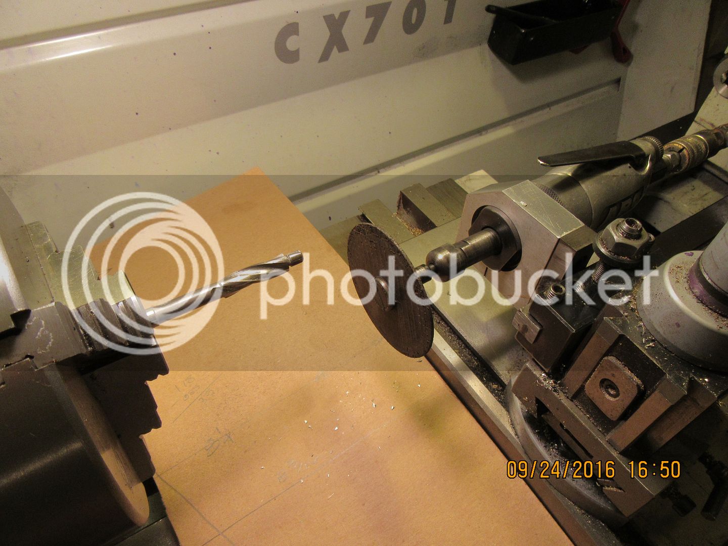
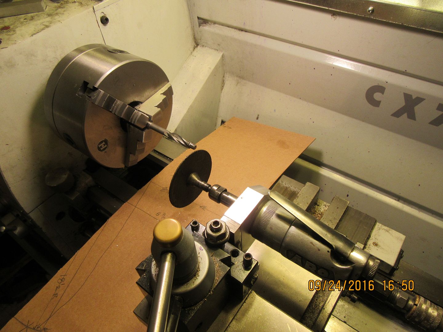
I have counterbores for #4, 5, 6, 8, 10, and 1/4" shcs. One of them (and I can't remember which one right now) has an exceptionally large pilot. Every time I have to use it, I tell myself I am going to set it up in the lathe and grind the pilot down, but so far I have never remembered to. I have made up an aluminum block which fits into my quick change toolpost to hold my pneumatic grinder for jobs like that.--Maybe tomorrow----
 
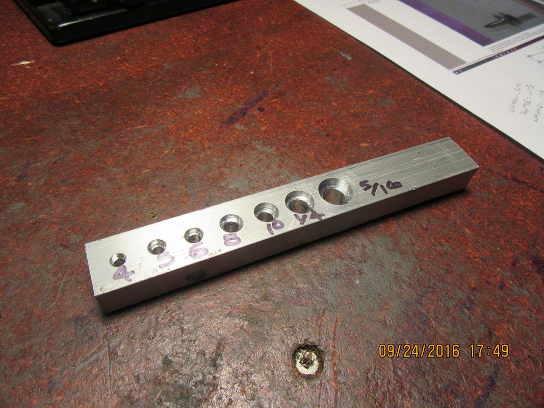
Today I set up a scrap piece of aluminum in the mill vice, and drilled the recommended size clearance holes for #4, 5, 6, 8, 10, 1/4" and 5/16" socket head cap screws, then tried all of my counterbore tools. The 1/4" and the 5/16" both had oversize pilots on them and wouldn't fit cleanly into the drilled clearance holes. (I didn't know when I bought them 6 or7 years ago that they even were available with different sized pilots.) Since I don't have a tool post grinder for my lathe, I did the next best thing----Improvise!!! This is NOT a recommendation that anyone else do it this way. This is simply what I done. I have a home-made mount for my pneumatic die grinder which fits in my quick change toolpost, with a 3" abrasive cut-off wheel. I was not looking for a high degree of accuracy here, simply a way of reducing the oversize pilots to a size that would fit into the drilled clearance hole in the aluminum, and keeping them concentric with the cutter o.d. I laid a piece of cardboard on the lathe ways to protect them, then with the lathe running at 200 rpm and the pneumatic grinder at ? rpm (medium fast), I took successive .005" deep cuts over the full length of the pilot (being very careful to not let the cut-off wheel touch the cutting edges of the actual counterbore tool). After each cut, I tried the aluminum bar with the hole in it to see if the pilot would fit into the hole. Not very scientific, but it worked well.


Latest posts

Back
Top