Two New Engines

Home Model Engine Machinist Forum

Help Support Home Model Engine Machinist Forum:

This site may earn a commission from merchant affiliate links, including eBay, Amazon, and others.
I'm about ready to start #2. The table has been a problem for me. Dimensions, proportions, material, style just haven't been working, at least not for this design. To my eyes, its just a little too fancy, requiring lot of detail and bling, and brass and the idea here is just to take the back acting mechanism from engine #1 and present it in a vertical design with minimal changes to the working parts, so ... while browsing in the scrap yard, I scored a 5" length of 4" OD aluminum pipe. It seems to make a more compatible engine design. Not really a table, but a vertical engine anyway.

What do you think?

Jerry


Vertical Cage Engine.jpg
 
Jerry,

To be honest, I'm not sure that I like it all that much and if you have to ask us, then I suspect that you too have doubts.

Best Regards
Bob
 
Bob, Kvom - Thank you for the responses. Its not that I just ignored them. Its just that I spent all day hacking away at that piece of pipe before I got a chance to read them. Now I've got sweat invested so I'm going to continue with the pipe version. It won't take long. This is a really easy engine to build and I already have the cylinder about half done from earlier in the project.

I have some pictures of today's work on the camera that need to be uploaded so I'll post the progress later tonight.

Jerry
 
The first thing to do to the pipe was to set it up in the lathe. Both the inner and outer surfaces were crusty but the cutoff end was clean and nearly square. I was able to grip it with the inside jaws and coax it into alignment with some hammer taps. The surface was too crusty to read with a DTI so I just used a tool in the toolpost and rotated the chuck by hand until I got constant contact through a full revolution.

The diameter was to big to fit in the steady and I was not going to power up without some outboard support so using a VERY sharp tool on the inside diameter and rotating the chuck by hand (belt tension off), I turned a clean contact area about 3/8" deep from the outer end, and also faced the outer end square. Then I reversed the part in the lathe and did the same process at the other end. It sounds tedious but it only took a few minutes.

Now that I had a true inner face, I turned a 3/8" thick disc to a tight push fit and now I had a place to put the live center for outboard support and could power up the lathe and turn the outer surface, just deep enough to remove all of the warts and gouges. It only took a few thou to get a nice clean surface from end to end.

pipework001.jpg


Now I have to figure out a way to hold it on the mill. I've got a 3 1/2" pipe and a 3" vise. My two tiny V-blocks won't help any. I resolved it by opening the vise as wide as it would go and using a table clamp to hold the pipe down. The pipe does not bottom out in the vise. Now I'm ready to mill something.

If I hadn't been paying attention when Stew Hart showed how he cut the popcorn engine trunk crosshead guide, I would have gone about this all wrong and made a mess of it. Thanks for the tip, Stew.

Here is how it works, just mill a notch deep enough to penetrate through to the inner face.

pipework009.jpg


Do that on both sides and then use a hacksaw to remove the waste.

pipework010.jpg


The purpose of the rectangular plate bolted onto the cylinder is to index the cylinder when it is rotated to do the other side and to set the depth of cut for the endmill so that I end up with two upright columns that are centered, parallel, and of equal width.

pipework006.jpg


Finish off the filet with a 1/2" ball nosed end mill.

pipework012.jpg


I still need to mill the shoulders for the bearing supports and to mill the openings in the two remaining faces to create the four column structure. That's for another day.

Jerry 4616
 
Jerry
I like the way you are turning that piece of pipe into what should be an attractive engine frame.
Ernie J
 
Thanks Ernie, I guess the jury is still out on how attractive it will be but it's beginning to take shape. Even after taking most of the waste off in chunks, there is an amazing amount of swarf coming off of this thing. The shop is a mess.

This is a picture left over from yesterday. Today's pictures were the victim of dead batteries in the camera.

pipework017-1.jpg


I won't get back to the shop until Monday. I'm going to visit with some old sailing friends who have gone ashore and headed for the hills of eastern Tennessee.

Jerry
 
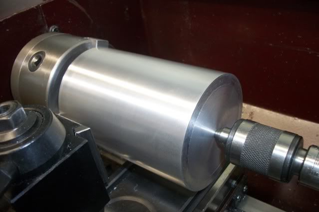
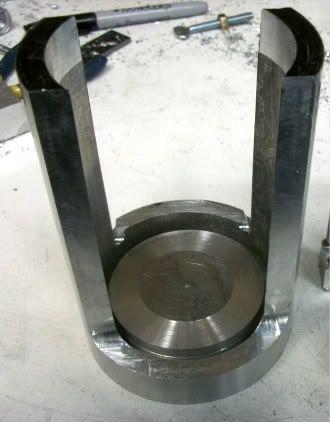
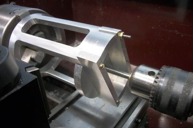
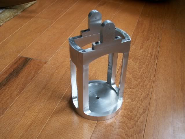
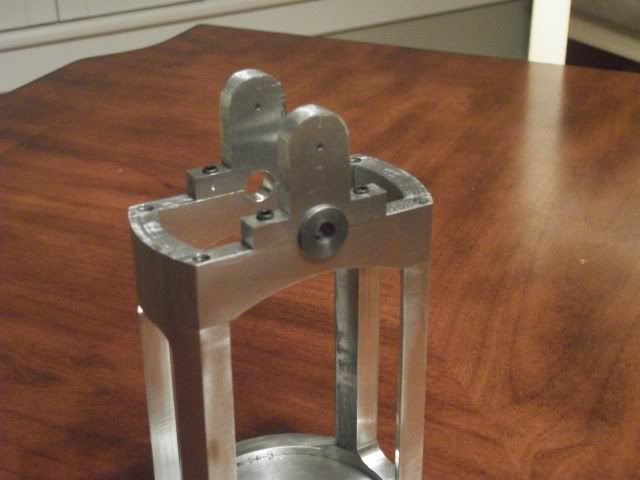
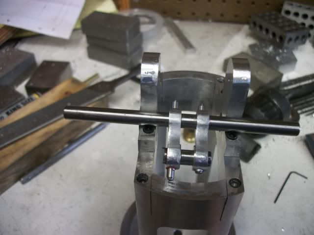
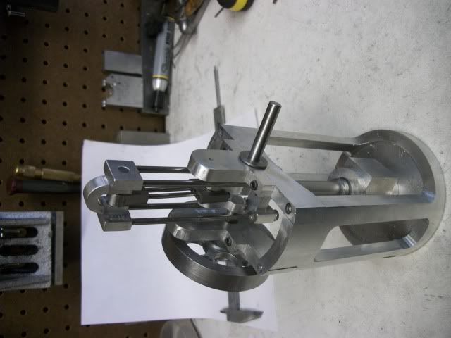
Full day in the shop today. I made lots of chip but it was very slow progress. Here is the end result:

cage006.jpg


Four notches to support the bearing beams and two openings through the pipe to give the four columns.

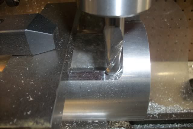
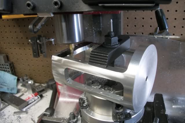
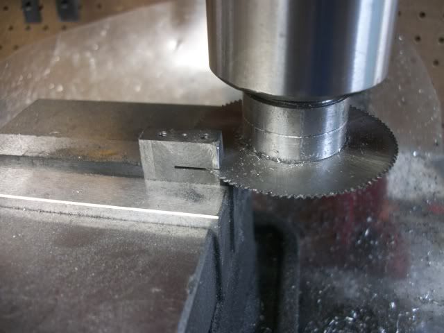
Not much to say about the notches. They are .75" by .28" but holding the pipe which is big for this mill is a bit of a challenge. Here it is held on the surface of the vise and held parallel to the X axis by the raised edge of the vise jaws spread open. A tall clamp reaches over the base to hold it down. The four notches required 4 separate setups because the "Y" axis travel is limited by the mounting of the "X" axis scale behind the table so I was unable to do two notches with one setup. There are other ways that I could have set the part and used the longer travel of the "X" axis but it would mean removing the vise.

cage003.jpg


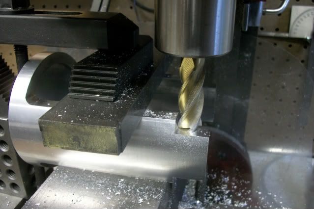
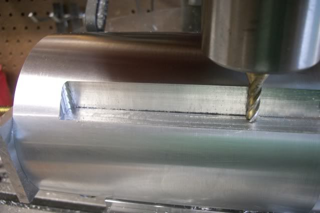
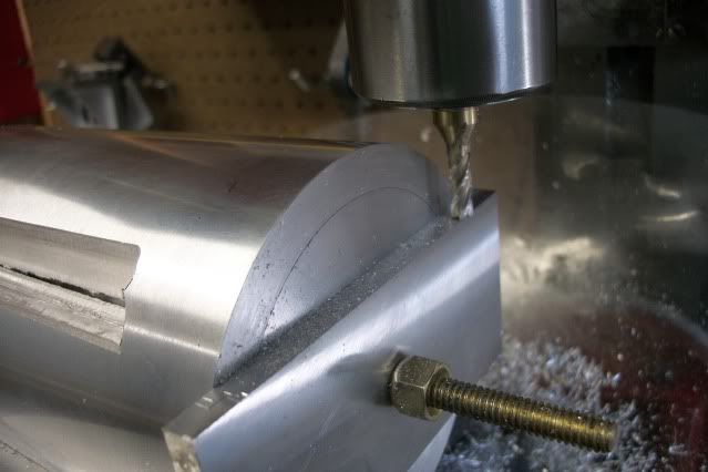
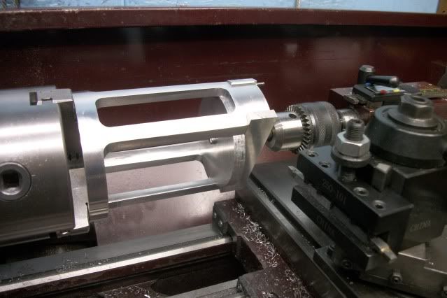
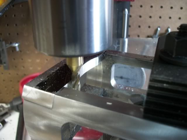
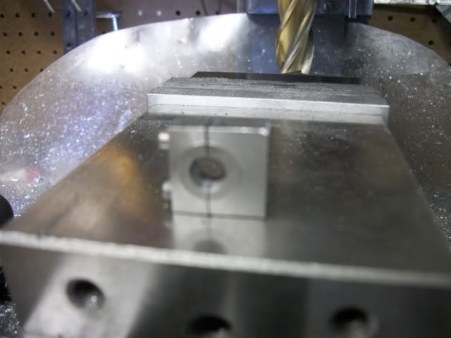
The rest of the day was used up cutting the two openings in the sides that are 1" wide and 4" tall. I had been thinking (fuzzy) that I would remove most of the waste with overlapping drilled holes but by the time I got the part clamped in the vise and held by two other hold down clamps, I had only about 1" between the part and the chuck. The only drill bit that I could get in the chuck was a centering drill so thats what I had to use to make the first entry into the hole. I could then get a 3/16" endmill in the hole. I had more overhead clearance when I switched to the R8 collet for the endmill but that is the largest endmill that I could get in the hole. I now began to make 4" long passes in a clockwise rotation around the slowly widening hole until it was the 1" wide needed.

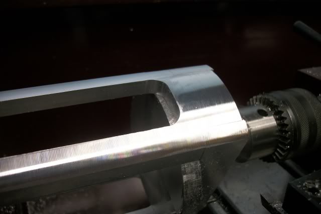
This was a very long and slow process because I was making cuts the full depth of the material (about 3/8") but with only .030" DOC. The setup was as stable and rigid as I could get it but the top of the part was more than 4" above the table and the head was at the upper end of the "Z" travel and although I was able to find a speed/feed rate that did not produce much chatter it was slow, dull, boring, repetitive cranking of the table. It was so dull that I almost fell asleep at the job. Really! The final few passes around the perimeter of the cutout were made with a 1/2" diameter end mill to provide the filet at the top and bottom of each column.

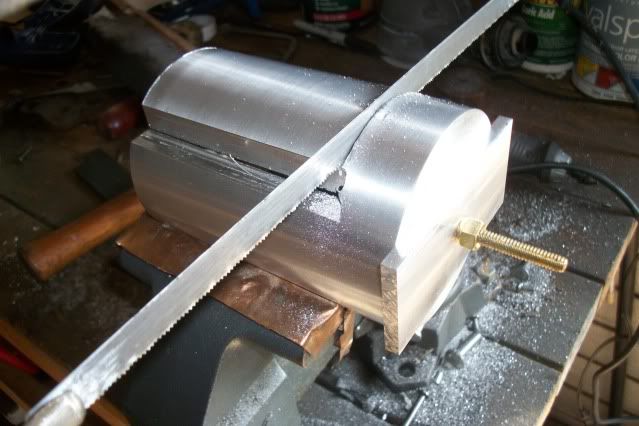
I was not willing to risk any greater depth for fear of ruining the part. Partly because of the time already invested in this part but also because there is no replacement for it. This is a big chunk of aluminum at scrapyard prices but I didn't see any more like it at the scrapyard and way more oney that I want to spend to order new on line.

I know a picture would be nice, BUT, when I got home from the shop, I went to get something out of the trunk of the car and when I was closing the trunk lid with the hand that was also holding the camera, something happened and the camera fell from a height of over six feet to the concrete driveway.

The camera still works, as far as I can tell, but the mem chip and the batteries popped out and now the chip refuses to give up the pictures that were stored on it this afternoon. Sorry. The only evidence that I have for this day's work is the picture at the top of this post of the progress made on this part.

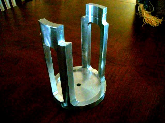
I have another chip so there will be ore interesting stuff to come. Next up are the bearing support cross beams that have a fairly large arc on the bottom edge that I don't know for sure how I will do it. Maybe the boring head, maybe a fly cutter.

Jerry
 
On the way to the shop this morning, I was thinking about how to produce the arc at the bottom of the bearing support beams and not even thinking about what would prove to be the biggest problem of the day. But first, I have to fit the beams to the base. A little touch with the file to be sure that the beams fit flush in the notches and then beam and base drilled, counter bored, and tapped #4-40 for a 1 1/4" SHCS. Turns out the longest #4-40 SHCS in the bin is only 1" long so an odd mixture of screws are filling the job until I can get to the fastener shop. Looks like this:

bearingbeams001.jpg


Now the big challenge becomes obvious. The overhanging ends of those beams need to be made flush with the curve of the base columns. All sorts of bad ideas came to my head, like hacksaw and file, disc and belt sander, but those thoughts were just putting off the obvious. It needs to be done on the lathe.

I can get a good grip on the base with the inside jaws but the beams are 5 inches out from the chuck and an interrupted cut at that. The outboard end needs support. Here is the final setup:

bearingbeams003.jpg


bearingbeams002.jpg


The aluminum disc fro the bottom is moved to the top, under the beams. The center hole has been enlarged to 3/8" and an oillite bushing pressed into it. A 1/4" tool steel rod is held in the tailstock chuck and the bushing turns on the rod. I was just mucking around, looking for inspiration and not at all sure that this would work out but when I put a DTI on it I was only about .012" out and with a few taps with a block of wood, I had it down to less than .002". I didn't think it would hold up to the interrupted cut but I thought I would give it a try. There was almost a 1/4" overhang on the ends of the beams so I could take a few passes and check again. This demands a sharp tool and a light cut so I touched up the tool on the diamond wheel and set a cut of .005" and had a try. I am using brazed carbide tools that are honed to a razor sharp edge with no top rake, minimal front relief, and a small radius on the tip. In the past I would have used HSS for this job but since I have learned how to shape a carbide tool effectively, I rarely use HSS.

On the first pass, only one beam end was sticking out far enough to take the cut and there was considerable pounding but when I checked the run out afterward, It had not moved. so I continued taking cuts of .005" until all four beam ends were flush with the cylinder. The I made a few passes on the full length of the cylinder at .002" DOC so everything was fair.

bearingbeams004.jpg


End of challenge. Piece of cake. I think the biggest challenge with jobs like this is overcoming fear. By this time, Ive got a lot invested in this part.

Now I can get to the job that had me worried all night. The curve on the bottom of the beams:

bearingbeams005.jpg


The hatched area needs to be cut away in a nice smooth circular arc. I got it done but it was not what I had planned. Its now after midnight and the story is to long to finish tonight. More tomorrow.

Jerry
 
Good job, and a nice set up well shown and explained.

Thanks for showing

Stew
 
sbwhart said:
Good job, and a nice set up well shown and explained.

Thanks for showing

Stew

Thanks for the comments, Stew. I was surprised at how well it worked out. I' getting better about figuring out how to get these unusual jobs done. Most of the time, the setup that works is not the one that I had planned the night before. I know that is from lack of experience. The arc on the bottom of the beams shown above is a good example.

Usually, when I encounter a long curve like this, it is an outside curve but on an inside curve like this there is no place to put a center pivot unless I bolt or clamp it to a larger plate. That was plan #1 and could have worked out if I had a plate big enough. Clamping would have to be worked out but I didn't have the necessary plate so on to plan #2.

Plan #2, Boring Head. My little 2" head doesn't swing a wide enough circle in the normal setup with the boring bar vertical, but there is a horizontal hole in the head that would swing a wide arc but when I started trying to work it out, it seems that I would have too have a reversible mill or left hand boring bars and a big dose of courage to make that work. I rejected the idea of a flycutter for reasons of courage. That's a big arc to swing.

Plan #3 involves using the rotary table but my table is only 4" so I would need a carrier plate or I would have to find a way to mount the cylinder on the table. That's the path I chose. The part is too big or the table is too Small to get a good clamping solution so I put a threaded rod up through the center hole and clamped it with a bar and nut across the top. I had to raise the base of the table to clear the nut on the bottom and use the outside jaws on the table to position the cylinder. All of that got pretty tall but R8 collets don't take up any Z so I have just enough room.

Positioning was not difficult. The center of the table must be centered under the spindle on the "Y" axis. The "X" axis will be used to adjust the depth of cut. The part must be centered on the RT in the "Y" as well. The "X" axis position on the table sets the center of the arc. That must be a thousand words, here's a picture:

bearingbeams006.jpg


A 3/16" end mill and moving the table to the right in small increments with repeated passes to bring the cut to final radius.

bearingbeams007.jpg


Job done. Easy.

I'm off to the shop. Upper bearing block with guide spools is next on the agenda.
 
Cap'n - I once flycut a 9&1/16 radius using a flycutter - mounted a boring bar with HSS tool through the horizontal hole in the boring head - set the radius and went for it.
I was young and stupid at the time and all the old hands said it wouldn't work - but it did.

This was on a Bridgeport - the job was an Aluminium dipole mount for the centre of a radar dish - eliptical about 6" long and 2" wide with the 9&1/16 rad in the face an approximation of the parabola at that point.

Got a lovely finish as well.

Chance favours the brave (and possibly stupid) - a cutter sticking out that far is damn dangerous.

Ken
 
Ken, I sometimes wonder why we fear big swinging cutters like that. I guess its just natural. After all, you don't intend to grab the thing! Fifty years ago, when I was learning how to demonstrate woodworking machinery in public, my instructor gave me some guidelines that I still rely on.

1. Know where BOTH hands are at all times.
2. Do not lean on the machine.
3. Know where your hands AND the part will be when the cut is finished.
4. Swing the cutter once by hand and be aware of what the cutter path is.
5. Be sure all guards are in place, but treat the machine as if it has no guards.
6. Have confidence, you don't want to scare the customers.
7. Don't joke about lost fingers, bad karma.

Woodworking machinery can be particularly dangerous because most of the time, you are holding the part in your hands and pushing it towards the cutter. Running a two bladed milling cuter with an 8" radius at 3400 RPM (basically a big flycutter) taking full profile cuts on a radial arm saw was an every day occurrence.

Now, on with the engine. Today's progress was just straight forward sawing and milling and drilling and counter boring and tapping but there were no critical or unusual setup problems to show. The result is that both upper halves of the bearing supports are installed on the cross beams.

standson012.jpg


The small hole in the center of the top radius is where the cast iron guide spools will be mounted. The crankshaft bore is located on the parting line between the beam and the top half. Tomorrow that will be drilled and reamed for the CI bushings that the shaft runs in.

This is a short post during halftime, Alabama vs LSU. The games starting up again, tied 3-3.

Jerry

 
2. Do not lean on the machine.

Although a bit OT and not a safety issue, I want to add to this. Next time you have an "I don't really care that much" piece mounted on the lathe, try leaning on the headstock. I don't mean touch it but rather lean the way you might lean on the bar after three Glenfiddichs at the local watering hole. Curse me if you won't see some interesting patterns in the workpiece assuming that you're using power feed.

The lesson: don't lean on the lathe/mill while trying to make a precision cut.

.
 
Just a small job but I can make it last all day. Crankshaft bushing are needed. The shaft shouldn't run in the aluminum frame and since I'm avoiding brass or bronze for this project, I'm going with cast iron. I toyed with the idea of split bushings but that's not really needed here. Here are the pics

2011-11-06standing.jpg


Upper left - Cast Iron Upper right - Cast iron without the rust and pipe threads drilled 15/64"

Lower Left - Turned to 3/8" for .28" Lower right - Parting off.

lots066.jpg


Here the bushing is pressed into the frame (Thumb Press):

I couldn't resist the urge to see how things are shaping up, so after hand reaming the bushings in the frame, I stuck a flywheel on a short shaft and gave it a spin. These CI bushings are slick, maybe better that oil-lite bronze. I couldn't stop there so I placed the unfinished cylinder in the base and propped the guide frame on a bar for this positional mock up.

lots069.jpg


Its beginning to look like an engine. If you compare this guide frame to the frame on the horizontal version, you might notice that the assembly nuts are not showing at the con-rod end of the frame. They have been moved to the piston end of the frame and the guide rods are threaded into blind holes in the top bracket. This will be a big focus point on this engine and I wanted to give it a cleaner appearance.

Crankshaft coming next.

Jerry

 
Well, I got a little more done today. The target was a crankshaft but it didn't quite get finished. I did get the webs finished but not yet glued or pinned to the shaft. They are a little different than those on engine #1. The lesson learned on #1 is that there is no room for counterweights. To make room for counterweights would mean moving the crankshaft further from the piston and that is counter to the purpose of a return crank engine which is to get the shaft as close to the cylinder as possible or more accurately, to get the piston as close to the crankshaft as possible.

On engine #1, when running at low speed 100-200 RPM the out of balance condition is not noticeable but at 300-400 RPM, the engine begins to slide back and fourth due to the unbalanced reciprocating mass of the piston, rod and sliding frame. Not much I can do about that on a single cylinder engine. At over 600 RPM, the engine starts to hop up and down. This is due to the unbalanced rotating mass of the crank webs and the connecting rod. Balancing the web and con-rod forces is the function of counterweights which are usually part of the crank web but can be added to the flywheel. That works fine on a dual flywheel engine but0 if added to the flywheel on a single flywheel engine it introduces a new off balance.

One thing that would help is to reduce the mass of the web and con-rod. The two rod con-rod on engine #1 is about as light as I can get it but I can reduce the mass of the webs in two ways. I can reduce the volume of material in the webs by careful profiling. I used the crank web style that is shown in this link:

http://www.shipsnostalgia.com/guides/William_Doxford_and_Sons

That shows the works of the William Doxford and Sons Ship Building. If you haven't seen these pics, be prepared to spend some time gawking. See if you can tell which pictures of the webs are at Doxfords and which ones are of the webs for engine #2 in my shop.

crankwebs003.jpg


If you have trouble telling the difference mine are the ones in the pictures that do not include very small people. Here is a pic of the webs positioned on the shaft:

crankwebs001.jpg


One other thing that I can do is to change from steel to aluminum. I know this may be controversial. I have seen aluminum used with full disk or large profile webs but I don't think I have seen it with small profile webs like this. I still think it should work. This is a low power, low impact steam engine and the web/shaft joint will be assemble with steel pins. Tell me if you have tried this and had a bad result. If it doesn't work, I can always make another one out of steel. It will just mean another day spent doing what I like to do.

Thanks for watching and thanks for your comments. 5580

Jerry
 
Pardon me for rushing. I really want to finish engine #2 before the end of the month. Holiday commitments, family visits, and trips to visit family will make it difficult to concentrate much after that. In addition to that, I got a call from an old cruising buddy who wants me to help him identify all of the damage that a lightning strike has done to his boat. The insurance co. is sending a surveyor but this is a good chance to hang out on the boat and sample some rum. This is the third time his boat has been hit. It is alongside his dock at his house and this time it got the house as well. Electronic thermostats and sprinkler controls are shot.

Back to the engine. Working on the crankshaft. The locktite has sat overnight so I can cut away the shaft between the throws and grind the stub ends of the pins and generally clean it up.

conrod001.jpg


conrod007.jpg


Next up is the con-rod. As on Engine #1, It will be a double bar connecting a split cast iron big end and a one piece cast iron small end. The CI for these parts was salvaged from a cheap import drill press vise that broke from over tightening.

conrod004.jpg


conrod005.jpg


conrod009.jpg


conrod012.jpg


conrod013.jpg


conrod015.jpg


conrod016.jpg


These pics are pretty much self explanatory. I'm in hurry-up mode and the setup pics are suffering but this is very repetitive from engine #1 and I don't want to bore anyone and drag this out.

But if there are any questions about any of these shots, just ask and I will give more of an explanation.

Thanks for watching. 5762

Jerry

 
Hello All, I just wanted to say that this project has not been abandoned. I just haven't been in the shop for a few weeks. I have been in a big hole in the ground, wondering how I got there. This is a 15' by 35' concrete swimming pool that has not been resurfaced in 40 years. No structural defects but the surface is full of hairline cracks, some of which have pitted and a few spots that have spalled to the concrete surface. Pressure wash, acid wash, pressure wash, grout, epoxy sealer and top coat. I am just about finished with the grout phase and so I will be at it for a few more weeks before I can add this to the list of things I have never done before and will never do again.

Jerry
 
For the past few weeks my shop time has been limited to short visits and the camera work suffered but I was pushing to get the second engine running so I could put it out of my mind for the holidays. The functional details of the vertical engine are the same as the horizontal one so It was just a matter of getting the fiddly bits done and adjusted. The only thing that is really different is the mounting of the cylinder and adjusting of the cylinder rod. Since the cylinder can't be moved, all adjustment must me made at the rod/slide frame connection. I was slightly short on the cylinder but I thought I could recover by reducing the piston thickness. I got it worked out but it is very close to hitting the head at either end. As it stands, there is a slight tap at one end of the stroke but I can't be sure whether it is the piston hitting the head or maybe a little slop in the valve rod knuckle. Anyway, The Vertical Back Acting Engine Makes it first public appearance:


I got a few ore videos to show but uploading is slow at the moment. More later.

Jerry
 

Latest posts

Back
Top